M-system 47DV Instruction Manual
Dc input digital panel meter
Hide thumbs
Also See for 47DV:
- Operating manual (34 pages) ,
- Manual (14 pages) ,
- Operating manual (254 pages)
Table of Contents
Advertisement
Quick Links
INSTRUCTION MANUAL
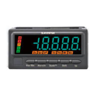
DC INPUT DIGITAL PANEL METER
(5 1/2 digit, LCD display type)
BEFORE USE ....
Thank you for choosing M-System. Before use, please check
contents of the package you received as outlined below.
If you have any problems or questions with the product,
please contact M-System's Sales Office or representatives.
■ PACKAGE INCLUDES:
Digital panel meter
(body + mounting bracket × 2 + watertight packing) ........(1)
Engineering unit sticker label sheet ..................................(1)
■ MODEL NO.
Confirm Model No. marking on the product to be exactly
what you ordered.
■ INSTRUCTION MANUAL
This manual describes necessary points of caution when
you use this product, including installation, connection and
basic maintenance procedures.
For detailed explanations to operate and program the mod-
ule, please refer to Model 47DV Operating Manual (EM-
9501-B).
The 47D Series is programmable either by using the front
control buttons or the PC Configurator Software. For de-
tailed information on the PC configuration, refer to the
47DCFG users manual.
Software and manuals are downloadable at M-System's
web site: http://www.m-system.co.jp
POINTS OF CAUTION
■ CONFORMITY WITH EU DIRECTIVES
• This equipment is suitable for Pollution Degree 2, Meas-
urement Category II (input and alarm output, transient
voltage 2500V) and Installation Category II (transient
voltage 2500V). Reinforced insulation (input or excita-
tion supply or DC output to alarm output to power: 300V)
and basic insulation (input or excitation supply to DC
output: 300V) are maintained. Prior to installation, check
that the insulation class of this unit satisfies the system
requirements.
• Altitude up to 2000 meters.
• The equipment must be installed such that appropriate
clearance and creepage distances are maintained to con-
form to CE requirements. Failure to observe these re-
quirements may invalidate the CE conformance.
• The actual installation environments such as panel con-
figurations, connected devices, connected wires, may af-
fect the protection level of this unit when it is integrated
in a panel system. The user may have to review the CE
requirements in regard to the whole system and employ
additional protective measures to ensure the CE conform-
ity.
• In order to enable the operator to turn off the power in-
put immediately, install a switch or a circuit breaker ac-
cording to the relevant requirements in IEC 60947-2 and
properly indicate it.
5-2-55, Minamitsumori, Nishinari-ku, Osaka 557-0063 JAPAN
Phone: +81(6)6659-8201 Fax: +81(6)6659-8510 E-mail: info@m-system.co.jp
MODEL
■ POWER INPUT RATING & OPERATIONAL RANGE
• Locate the power input rating marked on the product and
confirm its operational range as indicated below:
100 – 240V AC rating: 85 – 264V, 50/60 Hz, ≤ 12VA
24V DC rating: 24V ±10%, ≤ 3.5W
110V DC rating: 85 – 150V, ≤ 3.5W
■ GENERAL PRECAUTIONS
• Before you remove the unit or mount it, turn off the power
supply and input signal for safety.
• Be sure to put the terminal cover on while the power is
supplied.
■ ENVIRONMENT
• Indoor use.
• When heavy dust or metal particles are present in the
air, install the unit inside proper housing with sufficient
ventilation.
• Do not install the unit where it is subjected to continuous
vibration. Do not subject the unit to physical impact.
• Environmental temperature must be within -10 to +55°C
(14 to 131°F) with relative humidity within 30 to 90% RH
in order to ensure adequate life span and operation.
• Be sure that the ventilation slits are not covered with ca-
bles, etc.
■ REQUIREMENTS TO ENSURE IP66
• Observe the designated panel cutout size (W92 × H45
mm).
• The watertight packing included in the product package
must be placed behind the front cover.
• Both mounting brackets must be fastened tightly until
they hit the panel.
• Confirm visually that the packing is not contorted or ex-
cessively run off the edge after installation.
■ WIRING
• Make sure for safety that only qualified personnel per-
form the wiring.
• Do not install cables close to noise sources (high frequen-
cy line, etc.).
• Do not bind these cables together with those in which
noises are present. Do not install them in the same duct.
47DV
EM-9501-A Rev.8 P. 1 / 8
Advertisement
Table of Contents

Subscribe to Our Youtube Channel
Related Manuals for M-system 47DV


Summary of Contents for M-system 47DV
- Page 1 • Environmental temperature must be within -10 to +55°C For detailed explanations to operate and program the mod- (14 to 131°F) with relative humidity within 30 to 90% RH ule, please refer to Model 47DV Operating Manual (EM- in order to ensure adequate life span and operation. 9501-B).
-
Page 2: Viewing Angle
Terminal Block LIGHTNING SURGE PROTECTION Separable M-System offers a series of lightning surge protectors for Terminal Block protection against induced lightning surges. Please contact Screw M-System to choose appropriate models. -
Page 3: Component Identification
Used to change and apply setting values; or to execute/cancel Forced Zero and tare adjustment. Note: Refer to the operating manual for details on each function. EM-9501-A Rev.8 P. 3 / 8 5-2-55, Minamitsumori, Nishinari-ku, Osaka 557-0063 JAPAN Phone: +81(6)6659-8201 Fax: +81(6)6659-8510 E-mail: info@m-system.co.jp... -
Page 4: Terminal Connections
1.25 mm , stripped length 7 – 8 mm) EURO TYPE BCD output: 50-pin connector 50-pin CONNECTOR CONNECTOR TERMINAL (Honda Tsushin Kogyo HDR-E50LFDT1-SLE+) EM-9501-A Rev.8 P. 4 / 8 5-2-55, Minamitsumori, Nishinari-ku, Osaka 557-0063 JAPAN Phone: +81(6)6659-8201 Fax: +81(6)6659-8510 E-mail: info@m-system.co.jp... -
Page 5: Rear Terminal Assignments
Applicable wire wize 0.3 to 1.25 mm V3/I3 3 max 4 min REM2 sensor output 3.2 dia. – – sensor excitation +12V – – 12 max EM-9501-A Rev.8 P. 5 / 8 5-2-55, Minamitsumori, Nishinari-ku, Osaka 557-0063 JAPAN Phone: +81(6)6659-8201 Fax: +81(6)6659-8510 E-mail: info@m-system.co.jp... - Page 6 (when there is no cross-wiring), close across the terminal 12 – 13 with a leadwire. When the device is not at the end, no shortcircuit wire is required. EM-9501-A Rev.8 P. 6 / 8 5-2-55, Minamitsumori, Nishinari-ku, Osaka 557-0063 JAPAN Phone: +81(6)6659-8201 Fax: +81(6)6659-8510 E-mail: info@m-system.co.jp...
- Page 7 : 14 ZERO : 15 HOLD Hc, HHc 2 kΩ RESET 1.5 kΩ L OUTPUT open ZERO contact collector LL OUTPUT Lc, LLc EM-9501-A Rev.8 P. 7 / 8 5-2-55, Minamitsumori, Nishinari-ku, Osaka 557-0063 JAPAN Phone: +81(6)6659-8201 Fax: +81(6)6659-8510 E-mail: info@m-system.co.jp...
-
Page 8: System Configuration Examples
MDP-4R) * Digital Panel Meter Digital Panel Meter (model: 47Dx) (model: 47Dx) *1. Insert lightning surge protectors recommended in this example if necessary. EM-9501-A Rev.8 P. 8 / 8 5-2-55, Minamitsumori, Nishinari-ku, Osaka 557-0063 JAPAN Phone: +81(6)6659-8201 Fax: +81(6)6659-8510 E-mail: info@m-system.co.jp...
Need help?
Do you have a question about the 47DV and is the answer not in the manual?
Questions and answers