M-system 47DV Operating Manual
Dc input digital panel meter, 5 1/2 digit, lcd display type
Hide thumbs
Also See for 47DV:
- Manual (14 pages) ,
- Operating manual (254 pages) ,
- Instruction manual (8 pages)
Table of Contents
Advertisement
OPERATING MANUAL
DC INPUT DIGITAL PANEL METER
(5 1/2 digit, LCD display type)
BEFORE USE .... ........................................................................................................... 2
POINTS OF CAUTION ...................................................................................................... 2
COMPONENT IDENTIFICATION .......................................................................................... 3
VIEWING ANGLE ........................................................................................................... 4
INSTALLATION ............................................................................................................. 4
TERMINAL CONNECTIONS ............................................................................................... 5
MODBUS WIRING ......................................................................................................... 9
PC CONFIGURATION VIA INFRARED COMMUNICATION ............................................................. 9
SYSTEM CONFIGURATION EXAMPLES ............................................................................... 10
SETTING PROCEDURE .................................................................................................. 11
SCALING SETTING MODE .............................................................................................. 15
ALARM SETTING MODE ................................................................................................ 18
ADVANCED SETTING MODE ............................................................................................ 23
LOCKOUT SETTING MODE ............................................................................................. 31
MODBUS SETTING MODE .............................................................................................. 33
LOOP TEST OUTPUT MODE ............................................................................................ 34
INFRARED COMMUNICATION MODE ................................................................................. 34
ERROR MESSAGES ...................................................................................................... 34
CHARACTER SET ........................................................................................................ 34
CONTENTS
47DV
MODEL
EM-9501-B Rev.6
47DV
P. 1 / 34
Advertisement
Table of Contents

Related Manuals for M-system 47DV


Summary of Contents for M-system 47DV
-
Page 1: Table Of Contents
47DV OPERATING MANUAL DC INPUT DIGITAL PANEL METER 47DV MODEL (5 1/2 digit, LCD display type) CONTENTS BEFORE USE ....................... 2 POINTS OF CAUTION ...................... 2 COMPONENT IDENTIFICATION ..................3 VIEWING ANGLE ......................4 INSTALLATION ......................4 TERMINAL CONNECTIONS ....................5 MODBUS WIRING ...................... -
Page 2: Before Use
47DV BEFORE USE ..POINTS OF CAUTION Thank you for choosing M-System. Before use, please check ■ POWER INPUT RATING & OPERATIONAL RANGE contents of the package you received as outlined below. Locate the power input rating marked on the product and... -
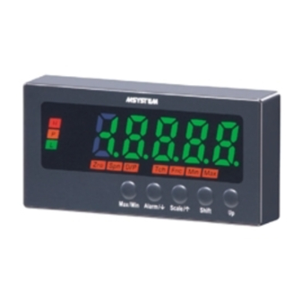
Page 3: Component Identification
47DV COMPONENT IDENTIFICATION ■ TOP VIEW Strap Specifications Watertight Sealing ■ FRONT VIEW ■ SIDE VIEW Mounting Bracket Terminal Cover (3) Status Indicators (1) Main Display (4) Alarm Indicators (2) Sub Display (5) Bargraph (6) Function Indicators Max/Min Alarm/ Scale/... -
Page 4: Viewing Angle
47DV VIEWING ANGLE The display is designed to provide the optimal legibility when viewed from the angles as shown below. INSTALLATION ■ PANEL CUTOUT unit: mm + 0.8 – 0 min. 120 Panel thickness: 1.6 to 8.0 mm ■ HOW TO MOUNT THE UNIT ON A PANEL The watertight packing must be in place to hold the meter. -
Page 5: Terminal Connections
47DV TERMINAL CONNECTIONS Connect the unit as in the diagram in the following page or refer to the connection diagram on the terminal cover. ■ EXTERNAL DIMENSIONS unit: mm (inch) ■ TOP VIEW 95 (3.74) ■ FRONT VIEW ■ SIDE VIEW 103 (4.06) - Page 6 47DV ■ CONNECTION DIAGRAM ■ REAR TERMINAL ASSIGNMENTS 14 15 16 ■ A : BASIC • Input Terminal Assignments V1/A1 MEASURING INPUT TYPE ID DC OUTPUT RANGE TERMINALS – V2/A2 1 – 5V 3 – 4 INPUT ±5V 3 – 4...
- Page 7 47DV ■ B • Alarm Output : N.O. contact, 4 points • Alarm Output : SPDT contact, 2 points Ha (NO) HH OUTPUT H OUTPUT Hb (NC) H OUTPUT Hc, HHc Hc (COM) La (NO) L OUTPUT L OUTPUT Lb (NC) LL OUTPUT...
- Page 8 47DV ■ C : BCD OUTPUT Open collector • Connector Pin Assignment PIN NO. ASSIGNMENT PIN NO. ASSIGNMENT Do 38 Output Do 34 PASS Do 32 Output Logic Do 31 Voltage Level at ON Output Logic Positive RESET Do 28...
-
Page 9: Modbus Wiring
47DV ■ TERMINAL BLOCK • How to remove the terminal block cover • How to remove the terminal block Insert the minus tip of a screwdriver into each hole at the The terminal block is separable in two pieces. Loosen two four corners of the cover and pull it to the direction as screws on both sides of the terminal block to separate. -
Page 10: System Configuration Examples
47DV SYSTEM CONFIGURATION EXAMPLES RS-485 / RS-232C RS-485 / ETHERNET RS-232C Ethernet RS-232C/RS-485 Converter Communication Adaptor (model: R2K-1 or LK1) (model: 72EM2-M4) ETHER NET SEND FIELD CNFG Lightning Surge Protector for RS-485/422 (model: MD74R or MDP-4R) *1 Lightning Surge Protector... -
Page 11: Setting Procedure
47DV SETTING PROCEDURE ■ INITIAL SETTING FLOWCHART POWER ON Hold down Scale/ button for 3 seconds or more to move on to Scaling Setting Mode. Choose an input type and display scale values. Hold down Alarm/ button for 3 seconds or more to move on to Alarm Setting Mode. - Page 12 47DV GENERAL SETTING FLOWCHART POWER ON Hold down Max/Min + Alarm/ buttons at once for a preset time duration* Lockout Setting Mode Measuring Mode Hold down Alarm/ or Scale/ Hold down Scale/ button button for ≥1 second for ≥3 seconds...
- Page 13 47DV ■ OPERATIONS IN MEASURING MODE • Switching the main display to MAX or MIN values Press Max/Min button to switch the main display to MAX or MIN values. ‘Max’ or ‘Min’ indicator turns on during the MAX/MIN display mode.
- Page 14 47DV • Tare Adjustment The display can be reset to zero against the Forced Zero point by Tare Adjustment. Display Forced Zero Canceled Tare Adj Canceled Tare Adj Forced Zero Executed Tare Adj Executed Executed Time 1 sec 1 sec...
-
Page 15: Scaling Setting Mode
47DV SCALING SETTING MODE ■ FLOWCHART Measuring Mode Hold down Scale/ button Hold down Alarm/ or Scale/ button for ≥3 seconds for ≥1 second Scaling Setting Mode Setting Parameters Scale/ Set value Shift 1-5V / -5-5V / 20V / 200V... - Page 16 47DV ■ PARAMETERS LIST DEFAULT PARAMETER SUB DISPLAY MAIN DISPLAY FUNCTION VALUE Measuring range 1 to 5V Input type Measuring range -5 to +5V Measuring range ±20V Measuring range ±200V Measuring range 0 to 20mA Measuring range 4 to 20mA Measuring range ±20mA...
- Page 17 47DV ■ FUNCTIONS, TERMINOLOGY • Scaling • Normal Scaling • Inverted Scaling The display value increases when the input signal increases. The display value decreases when the input signal increases. Display Display Full Scale Zero Span Span Display Scaling Display Scaling...
-
Page 18: Alarm Setting Mode
47DV ALARM SETTING MODE ■ FLOWCHART Measuring Mode Hold down Alarm/ button Hold down Alarm/ or Scale/ button for ≥3 seconds for ≥1 second Alarm Setting Mode Setting Parameters Scale/ Set value Shift 1, 2, 3, 4, 5, 6, 7, 8 Bank No. - Page 19 47DV Alarm/ Scale/ Alarm/ Scale/ Shift -20000...100000 H Setpoint Alarm/ Scale/ Alarm/ Scale/ Identical to LL H Alarm Level LV0 Setting Shift Trip action, Deadband, ON/OFF delay time, Ont-shot output, Coil at alarm Alarm/ Scale/ Alarm/ Scale/ Shift -20000...100000 HH Setpoint...
- Page 20 47DV ■ PARAMETERS LIST DEFAULT PARAMETER SUB DISPLAY MAIN DISPLAY FUNCTION VALUE Bank No. Bank No. Normal Alarm output pattern Zone LL: Setpoint value LL setpoint LL trip action * LL: Hi trip LL: Lo trip LL deadband (hysteresis) *...
- Page 21 47DV ■ FUNCTIONS, TERMINOLOGY • Alarm action basics Alarm trip operates in relation to the display value. Alarm indicators, except for P indicator, do not turn on until all parameters (display value, deadband, ON delay time elapsed) of the setpoint become true. Display color is switched accordingly.
- Page 22 47DV • Dedband (Hysteresis) Once a high trip alarm is ON, the alarm stays ON until the data becomes lower than the deadband value from the setpoint. Once a low trip alarm is ON, the alarm stays ON until the data becomes higher than the deadband value from the setpoint.
-
Page 23: Advanced Setting Mode
47DV ADVANCED SETTING MODE ■ FLOWCHART Measuring Mode Hold down Alarm/ + Scale/ button Hold down Alarm/ or Scale/ button at once for ≥3 seconds for ≥1 second Advanced Setting Mode Setting Parameters Scale/ Set value Shift NORMAL / S-HLD /... - Page 24 47DV Alarm/ Scale/ Alarm/ Scale/ Shift LL / L / H / HH / OFF P Output Alarm/ Scale/ Alarm/ Scale/ Shift OFF / OUT / ALL Latching Alarm Alarm/ Scale/ Alarm/ Scale/ Shift 000.0...999.9 Alarm Power ON Delay Alarm/...
- Page 25 47DV ■ PARAMETERS LIST DEFAULT PARAMETER SUB DISPLAY MAIN DISPLAY FUNCTION VALUE Normal Event trigger mode Sampling hold Peak hold Valley (Bottom) hold Peak-to-peak hold ON timing delay * Specify in seconds OFF timing delay * Specify in seconds Specify in seconds...
- Page 26 47DV DEFAULT PARAMETER SUB DISPLAY MAIN DISPLAY FUNCTION VALUE Standby sequence * Output immediately at the startup Output standing by until the input enters P zone Scaling error * Alarm trip action valid at over-range No alarm trip action at over-range...
- Page 27 47DV ■ FUNCTIONS, TERMINOLOGY • Event trigger mode All logical inputs in the following are in the negative logic (ON at Low signal, unchangeable). Normal Mode TIMING signal The status indicator turns on. However, the signal is invalid. Scaling error range...
- Page 28 47DV • Event trigger mode All event trigger inputs are negative logic (ON at Low signal, unchangeable). TIMING signal: Invalid in ‘Normal’ mode. Measures at the falling edge in ‘Sampling Hold’ mode. Measures while the signal is ON and establishes the measured value at the rising edge in ‘Peak Hold’, ‘Valley (Bottom) Hold’...
- Page 29 47DV • Low-end cutout Input signal below the preset cutout value is forcibly cut to 0. Typically used to avoid negative reading. Set for the three low- est digits of the scaled range (disregarding the decimal point). • Automatic return time to Measuring Mode The display goes back automatically to Measuring Mode if the front buttons are left untouched for the specified time period while it is in one of the setting modes (except the loop test output mode).
- Page 30 47DV • BCD output DATA signal is established in approx. 30 milliseconds upon detecting the falling pulse edge of REQ signal (REQ, MAX_REQ, MIN_REQ) and DAV turns on. Read in the data while the DAV is ON. RUN signal turns off in case of errors other than the scaling error. DATA and DAV signals turn off while RUN signal is OFF. The last measured value is held when HOLD signal turns on. All BCD signals turn off when RESET signal turns on. Data is in the negative range when POL signal is ON, in the positive range with OFF. OVER signal turns on in case of the scaling error. While in the loop test output mode, the analog/alarm outputs are provided according to the display reading, even when REQ signals are turned on.
-
Page 31: Lockout Setting Mode
47DV LOCKOUT SETTING MODE ■ FLOWCHART Measuring Mode Hold down Alarm/ + Max/Min button Hold down Alarm/ or Scale/ button at once for a preset time* for ≥1 second Lockout Setting Mode Setting Parameters Set value Shift LV0 / LV1 / LV2... - Page 32 47DV ■ PARAMETERS LIST DEFAULT PARAMETER SUB DISPLAY MAIN DISPLAY FUNCTION VALUE Completely unlock Alarm Setting Mode Alarm setting lockout Partially unlock Alarm Setting Mode * Lock Alarm Setting Mode Unlock Scaling Setting Mode Scaling setting lockout Lock Scaling Setting Mode...
-
Page 33: Modbus Setting Mode
47DV MODBUS SETTING MODE ■ FLOWCHART Measuring Mode Hold down Alarm/ + Shift button Hold down Alarm/ or Scale/ button for ≥3 seconds for ≥1 second Modbus Setting Mode Setting Parameters Set value Shift 001...247 Device Address Alarm/ Scale/ Alarm/... -
Page 34: Loop Test Output Mode
M-System’s option, the repair, replacement or refund of the purchase price of any M-System product which is defective under the terms of this warranty. To submit a claim under this warranty, the purchaser must return, at its expense, the defective M-System product to the below address together with a copy of its original sales invoice.
Need help?
Do you have a question about the 47DV and is the answer not in the manual?
Questions and answers