M-system 47 Series Manual
Thermocouple input digital panel meter
Hide thumbs
Also See for 47 Series:
- Operating manual (254 pages) ,
- Manual (13 pages) ,
- Specifications (7 pages)
Table of Contents
Advertisement
Quick Links
THERMOCOUPLE INPUT DIGITAL PANEL METER
(4-digit, LED display type)
MODEL & SUFFIX CODE SELECTION
MODEL
INPUT THERMOCOUPLE (field-configurable)
1 : (PR), K (CA), E (CRC), J (IC), T (CC),
B (RH), R, S, N
DC OUTPUT
0 : None
Voltage
Current
A : 4 – 20mA DC
4 : 0 – 10V DC
D : 0 – 20mA DC
5 : 0 – 5V DC
6 : 1 – 5V DC
4W : -10 – +10V DC
ALARM OUTPUT
0 : None
1 : N.O. relay contact, 4 points
2 : SPDT relay contact, 2 points
DISPLAY COLOR
R
: Red
YR : Orange
G
: Green
BG : Bluegreen
B
: Blue
W
: White
POWER INPUT
AC Power
DC Power
M2 : 100 – 240V AC
R : 24V DC
ORDERING INFORMATION
Specify code number. (e.g. 47LT-101G-M2)
GENERAL SPECIFICATIONS
Construction: Panel flush mounting
Degree of protection: IP66; applicable to the front panel
for the meter mounted according to the
specified panel cutout
Connection: M3 screw terminals
(nickel plated steel; torque 0.6 N·m)
Material:
Flame resistant resin (black)
Scaling:
Programming via the front buttons
Averaging: None or moving average
Security:
Prohibiting certain operations; protecting
settings
Specifications are subject to change without notice.
Digital Panel Meters 47 Series
47LT–1
–
❑❑❑
❑
Display:
Scaling:
Decimal point position: 10
Minimum display/setting scale: 1°C or 1°F (0.1°C for K
Read rate:
Over-range indication: 'S.ERR' flashing when the input
Burnout indication: 'B.ERR' flashing
Alarm status indication*
Zero indication: Higher-digit zeros are suppressed.
Engineering unit indication: Sticker label attached
*Only 'P' turns on with no-alarm-output type. 'LL' or 'HH'
does not turn on with dual-alarm-output type.
All setpoints can be independently set either for Hi or Lo
alarm trip.
MODEL
48
(1.89)
Functions & Features
• 4-digit thermocouple input digital panel meter
• 1/8 DIN size
• Moving average function to suppress the dis-
play flickering
• Max. and Min. value display
• IP66 front panel
• Separable terminal block
• Rear terminal cover for safety strapped to the
meter
DISPLAY
16 mm (.63) high, 4 digits (-1999 to 9999),
LED
No scaling (input temperature indication)
–1
the input type)
and J, narrow span)
Max. 40/second (25 milliseconds)
signal is out of the usable range.
LL indicator: Turns on when the LL alarm is tripped.
L indicator: Turns on when the L alarm is tripped.
H indicator: Turns on when the H alarm is tripped.
HH indicator: Turns on when the HH alarm is tripped.
P indicator: Turns on when none of the other alarms is
tripped.
47LT
47LT
96 (3.78)
Ma x/M in
98.5 (3.88)
Ala rm /
Init /
Sh ift
Up
mm (inch)
or none (fixed depending upon
ES-952 Rev.
P. / 9
Advertisement
Table of Contents

Related Manuals for M-system 47 Series


Summary of Contents for M-system 47 Series
- Page 1 47LT Digital Panel Meters 47 Series THERMOCOUPLE INPUT DIGITAL PANEL METER 47LT MODEL (4-digit, LED display type) MODEL & SUFFIX CODE SELECTION 96 (3.78) 47LT–1 – ❑❑❑ ❑ MODEL (1.89) INPUT THERMOCOUPLE (field-configurable) 1 : (PR), K (CA), E (CRC), J (IC), T (CC), Ma x/M in 98.5 (3.88)
-
Page 2: Input And Output
47LT INPUT & OUTPUT INSTALLATION ■ THERMOCOUPLE Power input Input resistance: 1MΩ minimum AC: Operational voltage range 85 – 264V Burnout sensing: ≤0.1µA 50/60 Hz, approx. 6.5VA Temperature Range DC: Operational voltage range 24V ±10% ripple 10% p-p max.; approx. 3W CONFORMANCE USABLE THERMOCOUPLE Operating temperature: -10 to +55°C (14 to 131°F) RANGE RANGE Operating humidity: 30 to 90% RH (non-condensing) (PR) °C 0 to 1700 -30 to +1730 Mounting: Panel flush mounting °F 32 to 3092 -22 to +3146 Panel cutout: W92×H45 mm (3.62”×1.77”) °C -200 to +1300 -230 to +1330... -
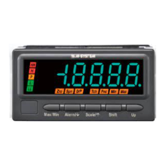
Page 3: Front Panel Configuration
47LT FRONT PANEL CONFIGURATION (1) Main Display (2) Alarm Indicators Alm D/P Fnc Min Max (3) Function Indicators Max/Min Alarm/ Init/ Shift (8) Up Button (4) Max/Min Button (5) Alarm/ Button (7) Shift Button (6) Init/ Button • COMPONENT IDENTIFICATION No. - Page 4 47LT SCHEMATIC CIRCUITRY & CONNECTION DIAGRAM ■ ALARM SUFFIX CODE 0: No alarm output comp. leadwire Isolation Output Driver DC OUTPUT – – – metal leg Converter U(+) Digital POWER Computation SENSOR V(–) Display / Setting ■ ALARM SUFFIX CODE 1: N.O. contact, 4 points comp.
-
Page 5: Setting Procedure
47LT SETTING PROCEDURE ■ INITIAL SETTING FLOWCHART POWER ON Hold down Init/ button for 3 seconds or more to move on to Initial Setting Mode. Choose an input type and display range values. Hold down Alarm/ button for 3 seconds or more to move on to Alarm Setting Mode. Go through the alarm settings. -
Page 6: Parameters List
47LT PARAMETERS LIST Refer to the instruction manual for details. ■ INITIAL SETTING MODE : Hold down Init/ button for 3 seconds or more to enter Initial Setting Mode. DEFAULT PARAMETER INDICATORS DISPLAY FUNCTION VALUE (PR) Input type K (CA) K (CA), narrow span E (CRC) J (IC) J (IC), narrow span T (CC) - Page 7 47LT ■ ALARM SETTING MODE : Hold down Alarm/ button for 3 seconds or more to enter Alarm Setting Mode. DEFAULT PARAMETER INDICATORS DISPLAY FUNCTION VALUE Dual alarm: L, H Alarm points Quad alarm: LL, L, H, HH LL: Setpoint value LL setpoint LL: Hi trip LL trip action...
- Page 8 47LT ■ ADVANCED SETTING MODE : Hold down Alarm/ + Init/ buttons at once for 3 seconds or more to enter Advanced Setting Mode. DEFAULT PARAMETER INDICATORS DISPLAY FUNCTION VALUE No moving averaging Moving average Moving average with 2 samples Moving average with 4 samples Moving average with 8 samples Brightness level 1 (dark)
-
Page 9: External Dimensions & Terminal Assignments
47LT EXTERNAL DIMENSIONS & TERMINAL ASSIGNMENTS unit: mm (inch) ■ TOP VIEW 95 (3.74) ■ FRONT VIEW ■ SIDE VIEW 103 (4.06) 98.5 (3.88) 96 (3.78) 12.5 (.49) 86 (3.39) 2 (.08) ■ REAR VIEW 10–M3 SCREW 20–M3 SCREW • Alarm Output TERMINAL TERMINAL •...
Need help?
Do you have a question about the 47 Series and is the answer not in the manual?
Questions and answers