M-system 47 Series Manual
Digital panel meters
Hide thumbs
Also See for 47 Series:
- Operating manual (254 pages) ,
- Manual (9 pages) ,
- Specifications (7 pages)
Table of Contents
Advertisement
Quick Links
Digital Panel Meters 47 Series
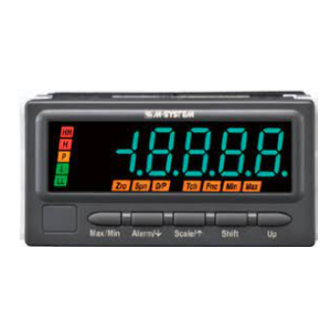
RTD INPUT DIGITAL PANEL METER
(5 digit, LCD display type)
Functions & Features
• 5 digit RTD input digital panel meter
• 1/8 DIN size
• Display color can be changed at alarm
• Bargraph indicator shows approximate measuring status
• 12 V or 24 V excitation supply
• External event trigger input
• RS-485 / Modbus RTU output
• Infrared interface
• BCD output
• Loop test output (DC output option)
• IP66 front panel
• Separable terminal block
• Safety terminal cover tethered to the device with a strap
96 (3.78)
48
(1.89)
Ma x/M in
Ala rm /
Init /
Sh ift
Up
MODEL: 47DR-1[1][2][3]-[4][5]
ORDERING INFORMATION
• Code number: 47DR-1[1][2][3]-[4][5]
Specify a code from below for each [1] through [5].
(e.g. 47DR-1111-M2/Q)
• Specify the specification for option code /Q
(e.g. /C01/S01/SET)
INPUT – Field-selectable
RTD
1: JPt 100 (JIS '89)
Pt 100 (JIS '89)
Pt 100 (JIS '97, IEC)
Pt 50Ω (JIS '81)
Pt 1000
[1] DC OUTPUT
0: Without
1: With
http://www.m-system.co.jp/
98.5 (3.88)
mm (inch)
47DR SPECIFICATIONS
[2] EXCITATION SUPPLY
1: +12 V sensor excitation
2: +24 V two-wire transmitter excitation
[3] I/O OPTIONS
0: None
1: Alarm output: N.O. relay, 4 points
2: Alarm output: SPDT relay, 2 points
3: Alarm output: N.O. photo MOSFET relay, 4 points
4: Network interface: RS-485 / Modbus RTU
5: BCD output
6: Event trigger input
7: Alarm output: N.O. relay, 4 points
+ Network interface: RS-485 / Modbus RTU
8: Alarm output: SPDT relay, 2 points +
Network interface: RS-485 / Modbus RTU
9: Alarm output: N.O. photo MOSFET relay, 4 points + BCD output
A: Event trigger input + BCD output
[4] POWER INPUT
AC Power
M2: 100 – 240 V AC (Operational voltage range 85 – 264 V, 50/60 Hz)
DC Power
R: 24 V DC
(Operational voltage range 24 V ±10 %, ripple 10 %p-p max.)
P: 110 V DC
(Operational voltage range 85 – 150 V, ripple 10 %p-p max.)
[5] OPTIONS
blank: none
/Q: With options (specify the specification)
SPECIFICATIONS OF OPTION: Q (multiple selections)
COATING (For the detail, refer to M-System's web site.)
Moving parts and indicators are not coated.
/C01: Silicone coating
/C02: Polyurethane coating
/C03: Rubber coating
TERMINAL SCREW MATERIAL
/S01: Stainless steel
EX-FACTORY SETTING
/SET: Preset according to the Ordering Information Sheet
(No. ESU-9509)
RELATED PRODUCTS
• Connector terminal block (model: CNT)
• Special cable (model: HDR40)
• Infrared Communication Adaptor (model: COP-IRU)
• PC configurator software (model: 47DCFG)
Downloadable at M-System's web site.
MODEL: 47DR
ES-9509 Rev.12 Page 1/12
Advertisement
Table of Contents

Related Manuals for M-system 47 Series


Summary of Contents for M-system 47 Series
- Page 1 Specify a code from below for each [1] through [5]. SPECIFICATIONS OF OPTION: Q (multiple selections) (e.g. 47DR-1111-M2/Q) COATING (For the detail, refer to M-System's web site.) • Specify the specification for option code /Q Moving parts and indicators are not coated.
-
Page 2: General Specifications
Sub display: 7 digits, LCD with LED backlight, 7-segment, Current rating: ≤ 22 mA DC 5.5 mm (.22) high • Shortcircuit Protection Color: Green Current limited: 30 mA max. Over-range indication: ‘S.ERR’ (main display) and ‘UNDER’ 47DR SPECIFICATIONS ES-9509 Rev.12 Page 2/12 http://www.m-system.co.jp/... -
Page 3: Input Specifications
Max. load voltage: 24 V DC HOLD: Hold data Max. load current: 10 mA Reading measured signal stops and the last value is held Saturation voltage: ≤ 0.3 V DC when HOLD signal is turned on. 47DR SPECIFICATIONS ES-9509 Rev.12 Page 3/12 http://www.m-system.co.jp/... -
Page 4: Installation
≤ 0.5 sec. (DC output: 0 – 90 %) Burnout response: ≤ 5 sec. Line voltage effect: ±0.1 % over voltage range Insulation resistance: ≥ 100 MΩ with 500 V DC Dielectric strength: 2000 V AC @ 1 minute 47DR SPECIFICATIONS ES-9509 Rev.12 Page 4/12 http://www.m-system.co.jp/... -
Page 5: External View
47Dx 47Dx RS-232-C *1. Internal terminating resistor is used when the device is at the end of a transmission line. *2. Install shield cables to all sections and ground them at single point. 47DR SPECIFICATIONS ES-9509 Rev.12 Page 5/12 http://www.m-system.co.jp/... - Page 6 6.6 (.26) 2–M3 SCREW 4–M3 SCREW 91.5 (3.60) • BCD Output, Event Trigger Input, Alarm Output (Photo MOSFET Relay) 10–M3 SCREW TERMINAL 2–M3 SCREW 14 15 16 EURO TYPE 50-pin CONNECTOR CONNECTOR TERMINAL 47DR SPECIFICATIONS ES-9509 Rev.12 Page 6/12 http://www.m-system.co.jp/...
- Page 7 DO NOT SHORT across the terminals 1 / 2 / 3 and 5 / 6. DO NOT SHORT across the terminals 1 / 2 / 3 and 5 / 6. Two-wire Transmitter SENSOR +12V 4 – 20mA DC +24V – – – RECEIV. INSTR. 47DR SPECIFICATIONS ES-9509 Rev.12 Page 7/12 http://www.m-system.co.jp/...
- Page 8 *1. When the device is located at the end of a transmission line via twisted-pair cable (when there is no cross-wiring), close across the terminal 12 – 13 with a leadwire. When the device is not at the end, no shortcircuit wire is required. 47DR SPECIFICATIONS ES-9509 Rev.12 Page 8/12 http://www.m-system.co.jp/...
- Page 9 Do12 1st LSD Do14 Do18 (polarity +, –) Digital Display Use Special cable (model: HDR40) and Connector Terminal Block (polarity +, –) (model: CNT). Refer to the cable’s data sheet for pin assignments. 47DR SPECIFICATIONS ES-9509 Rev.12 Page 9/12 http://www.m-system.co.jp/...
- Page 10 L OUTPUT ZERO LL OUTPUT Lc, LLc Connection Example TIMING : 11 S-TMR : 12 +6 V HOLD : 13 RESET : 14 ZERO : 15 2 kΩ 1.5 kΩ open contact collector 47DR SPECIFICATIONS ES-9509 Rev.12 Page 10/12 http://www.m-system.co.jp/...
-
Page 11: Viewing Angle
*1. DATA includes BCD Output, POL, OVF, HH, H, P, L, LL and RUN. *2. Wait for at least 20 ms between DAV turning off and the next REQ signal. REQ 1 47Dx REQ 2 47Dx REQ 3 47Dx 47DR SPECIFICATIONS ES-9509 Rev.12 Page 11/12 http://www.m-system.co.jp/... -
Page 12: System Configuration Examples
MDP-4R) * or MDP-4R) * Digital Panel Meter Digital Panel Meter (model: 47Dx) (model: 47Dx) *1. Insert lightning surge protectors recommended in this example if necessary. Specifications are subject to change without notice. 47DR SPECIFICATIONS ES-9509 Rev.12 Page 12/12 http://www.m-system.co.jp/...
Need help?
Do you have a question about the 47 Series and is the answer not in the manual?
Questions and answers