Table of Contents
Advertisement
Quick Links
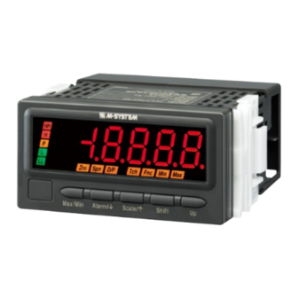
OPERATING MANUAL
POTENTIOMETER INPUT DIGITAL PANEL METER
(4-digit, LED display type)
BEFORE USE ....
Thank you for choosing M-System. Before use, please check
contents of the package you received as outlined below.
If you have any problems or questions with the product,
please contact M-System's Sales Office or representatives.
■ PACKAGE INCLUDES:
Digital panel meter ...................................................... (1)
Instruction manual ....................................................... (1)
Engineering unit sticker label sheet ........................... (1)
■ MODEL NO.
Confirm Model No. marking on the product to be exactly
what you ordered.
■ INSTRUCTION MANUAL
This manual describes necessary points of caution when
you use this product, including installation, connection and
basic maintenance procedures.
2.00 marked parameters are usable with the product ver-
sion 2.0 or higher.
POINTS OF CAUTION
■ CONFORMITY WITH EC DIRECTIVES
• This equipment is suitable for use in a Pollution Degree
2 environment and in Installation Category II, with the
maximum operating voltage of 300V.
Reinforced insulation is maintained between signal input,
output and power input, basic insulation is between the
input and DC output. Prior to installation, check that the
insulation class of this unit satisfies the system require-
ments.
• Altitude up to 2000 meters
• The equipment must be installed such that appropriate
clearance and creepage distances are maintained to con-
form to CE requirements. Failure to observe these re-
quirements may invalidate the CE conformance.
• In order to enable the operator to turn off the power input
immediately, install a switch or a circuit breaker accord-
ing to the relevant requirements in IEC 60947-1 and IEC
60947-3 and properly indicate it.
■ POWER INPUT RATING & OPERATIONAL RANGE
Locate the power input rating marked on the product and
confirm its operational range as indicated below:
100 – 240V AC rating: 85 – 264V, 50/60 Hz, approx. 6.5VA
24V DC rating: 24V ±10%, approx. 3W
110V DC rating: 85 – 150V, approx. 3W
■ GENERAL PRECAUTIONS
• Before you remove the unit or mount it, turn off the power
supply and input signal for safety.
• Be sure to put the terminal cover on while the power is
supplied.
MODEL
■ ENVIRONMENT
• Indoor use
• When heavy dust or metal particles are present in the air,
install the unit inside proper housing with sufficient ven-
tilation.
• Do not install the unit where it is subjected to continuous
vibration. Do not subject the unit to physical impact.
• Environmental temperature must be within -10 to +55°C
(14 to 131°F) with relative humidity within 30 to 90% RH
in order to ensure adequate life span and operation.
• Be sure that the ventilation slits are not covered with ca-
bles, etc.
■ REQUIREMENTS TO ENSURE IP66
• Observe the designated panel cutout size (W92 × H45
mm).
• The watertight packing included in the product package
must be placed behind the front cover.
• Both mounting brackets must be fastened tightly until
they hit the panel.
• Confirm visually that the packing is not contorted or ex-
cessively run off the edge after installation.
■ WIRING
• Make sure for safety that only qualified personnel per-
form the wiring.
• Do not install cables (power supply, input and output)
close to noise sources (high frequency line, etc.).
• Do not bind these cables together with those in which
noises are present. Do not install them in the same duct.
■ AND ....
The unit is designed to function as soon as power is sup-
plied, however, a warm up for 10 minutes is required for sat-
isfying complete performance described in the data sheet.
47LM
47LM
EM-9504-B Rev.1
P. / 6
Advertisement
Table of Contents

Related Manuals for M-system 47LM


Summary of Contents for M-system 47LM
- Page 1 • Indoor use • When heavy dust or metal particles are present in the air, Thank you for choosing M-System. Before use, please check install the unit inside proper housing with sufficient ven- contents of the package you received as outlined below.
-
Page 2: Component Identification
47LM COMPONENT IDENTIFICATION ■ TOP VIEW Strap Specifications Watertight Sealing ■ FRONT VIEW ■ SIDE VIEW Mounting Bracket Terminal Cover (1) Main Display (2) Alarm Indicators Spn D/P Tch Fnc Min Max (3) Function Indicators Max/Min Alarm/ Scale/ Shift (8) Up Button... -
Page 3: Installation
47LM INSTALLATION ■ HOW TO MOUNT THE UNIT ON A PANEL ■ PANEL CUTOUT unit: mm The watertight packing must be in place to hold the meter. + 0.8 – 0 Do not remove it. 1) Insert the unit into the panel cutout. - Page 4 47LM ■ CONNECTION DIAGRAM ■ ALARM SUFFIX CODE 0: No alarm output POTENTIOMETER max. DC OUTPUT – – U(+) min. POWER V(–) ■ ALARM SUFFIX CODE 1: N.O. contact, 4 points ■ ALARM SUFFIX CODE 2: SPDT contact, 2 points...
-
Page 5: Setting Procedure
47LM SETTING PROCEDURE ■ INITIAL SETTING FLOWCHART POWER ON Hold down Scale/ button for 3 seconds or more to move on to Scaling Setting Mode. Hold down Alarm/ button for 3 seconds or more to move on to Alarm Setting Mode. - Page 6 47LM ■ OPERATIONS IN MEASURING MODE • Switching the main display to MAX or MIN values Press Max/Min button to switch the main display to MAX or MIN values. ‘Max’ or ‘Min’ indicator turns on during the MAX/MIN display mode.
- Page 7 47LM ■ OPERATIONS IN SETTING MODES • Main display The main display shows the current settings while the panel meter is in the setting mode. • Shifting through setting parameters In any setting mode, pressing Alarm/ button shifts one parameter to the next. Pressing Scale/ button shifts one to the previous.
- Page 8 47LM ■ SCALING SETTING MODE Measuring Mode Hold down Scale/ button Hold down Alarm/ or Scale/ button for ≥3 seconds for ≥1 second Scaling Setting Mode Setting Parameters Scale/ Set value Input Scaling Value A Teach Calibration (Zero) Up (set)
- Page 9 47LM DEFAULT PARAMETER INDICATORS DISPLAY FUNCTION VALUE Input scaling value A Input value for Zero point: Set to a specific value by using the buttons, or by Teach Calibration (Factory setting and default value 0Ω though not indicated) Display value for Input Scaling Value A...
- Page 10 47LM ■ ALARM SETTING MODE Measuring Mode Hold down Alarm/ button Hold down Alarm/ or Scale/ button for ≥3 seconds for ≥1 second Alarm Setting Mode Setting Parameters Scale/ Set value Shift 2 / 4* Alarm Point Alarm/ Scale/ Alarm/...
- Page 11 47LM Alarm/ Scale/ Alarm/ Scale/ Shift -9999...9999 H Setpoint Alarm/ Scale/ Alarm/ Scale/ Shift LMHI / LMLO H Trip Action Alarm/ Scale/ Alarm/ Scale/ Shift 0000...9999 H Deadband Alarm/ Scale/ Alarm/ Scale/ Shift 00...99 H ON Delay Time Alarm/ Scale/...
- Page 12 47LM DEFAULT PARAMETER INDICATORS DISPLAY FUNCTION VALUE Dual alarm: L, H Alarm points Quad alarm: LL, L, H, HH LL: Setpoint value LL setpoint LL: Hi trip LL trip action 2.00 LL: Lo trip LL deadband (hysteresis) LL: Deadband (hysteresis) value...
- Page 13 47LM ■ ADVANCED SETTING MODE Measuring Mode Hold down Alarm/ + Scale/ button Hold down Alarm/ or Scale/ button at once for ≥3 seconds for ≥1 second Advanced Setting Mode Setting Parameters Scale/ Set value Shift OFF / 2 / 4 / 8 / 16 / 32 / 64...
- Page 14 47LM DEFAULT PARAMETER INDICATORS DISPLAY FUNCTION VALUE No moving averaging Moving average Moving average with 2 samples Moving average with 4 samples Moving average with 8 samples Moving average with 16 samples 2.00 Moving average with 32 samples 2.00 Moving average with 64 samples 2.00...
- Page 15 47LM ■ LOCKOUT SETTING MODE Measuring Mode Hold down Alarm/ + Max/Min button Hold down Alarm/ or Scale/ button at once for a preset time* for ≥1 second Lockout Setting Mode Setting Parameters Set value Shift OFF / ON Alarm Setting Lockout...
-
Page 16: Error Messages
E F G J K L O P Q T U V W X LIGHTNING SURGE PROTECTION M-System offers a series of lightning surge protectors for protection against induced lightning surges. Please contact M-System to choose appropriate models. M-SYSTEM WARRANTY M-System warrants such new M-System product which it manufactures to be free from defects in materials and workmanship during the 36-month period following the date that such product was originally purchased if such product has been used under normal operating conditions and properly maintained, M-System’s sole liability, and purchaser’s exclusive...
Need help?
Do you have a question about the 47LM and is the answer not in the manual?
Questions and answers