M-system 47 Series Operating Manual
Digital panel meters, pulse input totalizer, 6-digit, led display type
Hide thumbs
Also See for 47 Series:
- Operating manual (254 pages) ,
- Manual (13 pages) ,
- Specifications (7 pages)
Table of Contents
Advertisement
Quick Links
Digital Panel Meters 47 Series
PULSE INPUT TOTALIZER
(6-digit, LED display type)
Model: 47LPQ
OPERATING MANUAL
5-2-55, Minamitsumori, Nishinari-ku, Osaka 557-0063 JAPAN
Tel: +81-6-6659-8201
Fax: +81-6-6659-8510
http://www.m-system.co.jp/
E-mail: info@m-system.co.jp
47LPQ OPERATING MANUAL EM-9516-B Rev.10
1
Advertisement
Table of Contents

Related Manuals for M-system 47 Series


Summary of Contents for M-system 47 Series
- Page 1 Digital Panel Meters 47 Series PULSE INPUT TOTALIZER (6-digit, LED display type) Model: 47LPQ OPERATING MANUAL 5-2-55, Minamitsumori, Nishinari-ku, Osaka 557-0063 JAPAN Tel: +81-6-6659-8201 Fax: +81-6-6659-8510 http://www.m-system.co.jp/ E-mail: info@m-system.co.jp 47LPQ OPERATING MANUAL EM-9516-B Rev.10...
-
Page 2: Table Of Contents
CONTE NTS 1. INTRODUCTION ..................6 1.1 BEFORE USE........................6 1.2 SAFETY PRECAUTIONS (Be sure to observe.) ..............7 1.3 POINTS OF CAUTION ......................9 1.4 COMPONENT IDENTIFICATION ..................11 1.5 INSTALLATION........................15 1.5.1 EXTERNAL DIMENSIONS ..................15 1.5.2 PANEL CUTOUT DIMENSIONS ................15 1.5.3 INSTALLATION ....................... - Page 3 4. SETTING SCALING VALUES ..............36 4.1 STEP 1. DISPLAY SCALING VALUE A ................38 4.1.1 DISPLAY SCALING LIST ..................38 4.1.2 OPERATING PROCEDURE ...................38 4.2 STEP 2. INPUT SCALING VALUE B .................41 4.2.1 INPUT SCALING LIST ....................41 4.2.2 OPERATING PROCEDURE ...................41 4.3 STEP 3. DISPLAY SCALING VALUE B ................44 4.3.1 OPERATING PROCEDURE ...................44 4.4 STEP 4.
- Page 4 10. SETTING OVERFLOW COUNT MODE ..........83 10.1 OPERATING PROCEDURE .....................84 11. SETTING CONTROL INPUT FUNCTION ...........86 11.1 OPERATING PROCEDURE ....................88 12. SETTING COUNTED PULSE EDGE ..........90 12.1 COUNTING ON PULSE EDGES ..................90 12.2 OPERATING PROCEDURE .....................91 13. SETTING PRESENT/MAX/MIN COUNT MEMORY ......93 13.1 OPERATING PROCEDURE .....................93 14.
- Page 5 20. USER CALIBRATION ............... 117 20.1 ANALOG OUTPUT ADJUSTMENT ................117 20.1.1 ANALOG OUTPUT ADJUSTMENT FLOW ............117 20.1.2 OPERATING PROCEDURE ................118 21. INSPECTION / CLEANING ...............121 22. TROUBLESHOOTING ..............122 22.1 ERROR MESSAGES ...................... 122 22.2 INITIALIZING SETTING VALUES ................... 122 22.2.1 OPERATING PROCEDURE ................
-
Page 6: Introduction
1. INTRODUCTION 1.1 BEFORE USE..Thank you for choosing M-System. Before use, please check contents of the package you received as outlined below. ■ PACKAGE INCLUDES Digital panel meter Accessories Mounting bracket (2) Terminal cover (1) Watertight packing (1) (tethered to the meter with a strap) -
Page 7: Safety Precautions (Be Sure To Observe.)
1.2 SAFETY PRECAUTIONS (Be sure to observe.) The following signs are used in this manual to provide precautions required to ensure safe usage of the unit. Please under- stand these signs and graphic symbols, read the manual carefully and observe the description. The following signs show seriousness of safety hazard or damage occurred when used wrongly with the signs ignored. - Page 8 Tighten the terminal blocks and terminal block screws with a specified torque. • Excessive fastening may result in damage of the screws and loose screws may occasionally result in ignition. Do not throw the unit into the fire. • Doing so may result in rupture of the electronic component. Never discompose or remodel the unit.
-
Page 9: Points Of Caution
CE requirements. Failure to observe these requirements may invalidate the CE conformance. • M-System’s products conforming to the EU Directives conforms to the standards required based on the premise that they are built into various equipment, apparatus or control panels to use. Because the EMC performance depends on the configuration, wiring or arrangement of the equipment, apparatus and control panels you build, it is necessary for you to make such equipment, apparatus or control panels to conform finally to the CE Marking by yourselves. - Page 10 To ensure dustproof and waterproof for front panel follow conditions below. • Observe the designated panel cutout size (W92 × H45 mm) specified by M-System. • The watertight packing included in the product package must be placed between the body and panel when installing on the panel.
-
Page 11: Component Identification
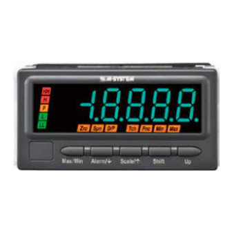
1.4 COMPONENT IDENTIFICATION ■ FRONT VIEW Display Engineering unit sticker label position BUTTON FUNCTION Max/Min Used to switch the main display to show the present value, MAX value or MIN value, and to reset the MAX and MIN values. Also used to cancel a set item. ↓... - Page 12 ■ DISPLAY COMPONENT FUNCTION Main display Indicates present, MAX and MIN values, parameters, setting values and error codes. INDICATOR MODE FUNCTION INDICATOR MODE FUNCTION Alarm Setting Indicates parameters in Alarm Function Setting Indicates parameters in each Setting Mode. mode. (Refer to 8. SETTING ALARM ‘Ini’...
- Page 13 • The tag No. label sticker position is our recommended position. • When a tag No. is specified, the unit(s) will be shipped with the tag No. sticker label put on the above position. Max. 17 alphanumeric characters can be specified. Please consult M-System’s Hotline. 47LPQ OPERATING MANUAL EM-9516-B Rev.10...
- Page 14 ■ REAR VIEW • With Terminal Cover Connection diagram Terminal cover Strap Model No. NOTE • The connection diagram depends on the specifications. • The MODEL shows the same as that in the specification label on the top of the unit. •...
-
Page 15: Installation
1.5 INSTALLATION 1.5.1 EXTERNAL DIMENSIONS unit: mm (inch) TOP VIEW 95 (3.74) FRONT VIEW SIDE VIEW 103 (4.06) 98.5 (3.88) 96 (3.78) 12.5 (.49) 86 (3.39) 2 (.08) REAR VIEW 10–M3 SCREW 20–M3 SCREW • Alarm Output • No Alarm Output TERMINAL TERMINAL 6.6 (.26) -
Page 16: Installation
1.5.3 INSTALLATION (1) Remove the terminal cover. (a) Insert the minus tip of a screwdriver into a hole at the lower left corner of the cover. (b) Pull the handle upward. (c) Then insert the screwdriver into a hole at the lower right corner. (d) Pull the handle upward to separate the terminal cover. - Page 17 (4) Make sure that the watertight packing is placed behind the front cover regardless of necessity of water-tightness. Watertight packing (5) Insert the unit into the panel cutout. Panel Watertight packing (6) Push the mounting brackets into the grooves on both sides of the rear module, until they hit the panel’s rear side. Panel Bracket Fixing groove...
-
Page 18: Wiring Instructions
• Be sure to confirm the name and polarity of each terminal before wiring to it. • Do not connect anything to unused terminals. • M-System offers a series of lightning surge protectors for protection against induced lightning surges. Please contact M- System to choose appropriate models. -
Page 19: Wiring Input Signal
1.6.4 WIRING INPUT SIGNAL Connect input signal wires. Be careful that the input terminal assignment depends on the sensor to connect. Sensor excitation 12 V DC ±10% Sensor excitation current 30 mA Current limit protection Approx. 60 mA IMPORTANT • The connection depends on the sensor output specifications. Wrong connection may result in incorrect display. •... - Page 20 ■ OPEN COLLECTOR, MECHANICAL CONTACT An open collector output, other no-voltage switches (including a relay, a photo MOS relay, and an open drain), a totem pole output, or a complementary output circuit can be connected. Connecting conditions are as shown in the following table. Detecting voltage Approx.
- Page 21 ■ VOLTAGE PULSE A voltage output circuit, a totem pole output or a complementary output circuit can be connected. Connecting conditions are as shown in the following table. Voltage range 0 – 5 through 26.4 V ±5 to ±26.4 V (equal amplitude at both poles) Waveform Square (detecting sinking pulse edges) Input impedance...
- Page 22 ■ CONTROL INPUT Voltage input can be connected. When it is difficult to prepare the power supply, short-circuit across the terminals. Connecting conditions are as shown in the following tables. • Voltage input Voltage range 0 – 5 through 26.4 V ±5 to ±26.4 V (equal amplitude at both poles) Detecting levels Low level...
-
Page 23: Wiring Dc Output
1.6.5 WIRING DC OUTPUT Voltage or current is output depending on the specified DC output code. IMPORTANT • Connect load resistance within the specifications. • Do not connect anything with no-DC-output type. • Take measures to reduce noise as much as possible, e.g. by using shielded twisted pair wires for the output signal. Ground the output shield to the most stable earth to prevent noise troubles. -
Page 24: Wiring Power
NOTE Example of contact protection circuit with inductive load ■ DC powered ■ AC powered 47LPQ 47LPQ Power Power Varistor Diode Varistor circuit circuit * It is effective to connect a varistor across a load with the supply voltage 24 to 28 V, and across a contact with 100 to 200 V. 1.6.7 WIRING POWER Connect power according to the power input code. -
Page 25: Installing/Separating Terminal Block
1.6.8 INSTALLING/SEPARATING TERMINAL BLOCK The terminal block is separable in two pieces. Tighten (loosen) uniformly two screws on both sides of the terminal block to install (separate). Torque: 0.6 N∙m IMPORTANT Be sure to turn off the power supply, input signal and power supply to the output relays before installing/separating the terminal block. - Page 26 ■ REMOVING TERMINAL COVER (a) Insert the minus tip of a screwdriver into a hole at the lower left corner of the cover. (b) Pull the handle upward. (c) Then insert the screwdriver into a hole at the lower right corner. (d) Pull the handle upward to separate the terminal cover.
-
Page 27: Basic Setting And Operation
2. BASIC SETTING AND OPERATION 2.1 BASIC SETTING This section describes flow and procedure of the basic setting. The following shows the flow and procedure to set pulse count for an hour with the pulse unit 0.1 m /p and max. flow rate 150 m /min. -
Page 28: Relation Between Input Scaling And Display Scaling
2.1.3 RELATION BETWEEN INPUT SCALING AND DISPLAY SCALING The relation between input scaling and display scaling is as shown in the following figure and chart. Display value 9000.0 m Input scaling value A Input scaling value B Input scaling Count 0 Count 90000 Display scaling value A Display scaling value B... -
Page 29: Basic Setting Procedure
2.1.4 BASIC SETTING PROCEDURE The following shows the procedure to set pulse count for an hour with the pulse unit 0.1 m /p and max. flow rate 150 m min. as an example. Set values meeting signals to use. The input scaling value A is fixed to 000000. Refer to 3. SETTING INPUT TYPE for details of setting. -
Page 30: Basic Setting Operation And Instructions
2.2 BASIC SETTING OPERATION AND INSTRUCTIONS This section describes basic operation and instructions when setting parameters. 2.2.1 BASIC SETTING OPERATION Parameters can be grouped into three setting types, “numerical value setting” , “setting value selection” and “decimal point position selection” . Basic operation of each type is as shown below. ■... - Page 31 ■ SETTING VALUE SELECTION Press Shift button to shift the display into the setting standby mode. • The current set value starts blinking. Press Up button to select your desired setting value. Press Alarm/↓ or Init/↑ button to apply the new setting. •...
-
Page 32: Instructions On Basic Operation
NOTE ■ MOVING THE DECIMAL POINT Pressing Up button moves the decimal point one place to the left. 5 decimal places (10 4 decimal places (10 3 decimal places (10 2 decimal places (10 1 decimal place (10 No decimal point ■... -
Page 33: Setting Input Type
3. SETTING INPUT TYPE Set input type according to the maximum frequency to input. With max. frequency ≤100 Hz, choose the input type ‘1’ (no counting scaling). With 100 Hz < max. frequency ≤ 10 kHz, choose the type ‘100’ (counting scaled to 1/100). With max. frequency ≤... -
Page 34: Operating Procedure
3.2 OPERATING PROCEDURE Procedures to change ‘1’ (no counting scaling) (default) to ‘100’ (counting scaled to 1/100) are described here. NOTE • Procedures to change ‘1’ to ‘100’ are described here. • To change ‘100’ to ‘1’ , the procedures are same. Select ‘1’... - Page 35 Press Up button to select the input type. Blinking • Select ‘100’ (counting scaled to 1/100). Press Alarm/↓ or Init/↑ button to apply the new setting. • And the next parameter setting is indicated. NOTE • Press Alarm/↓ button, and the input scaling value A will be indicated. •...
-
Page 36: Setting Scaling Values
4. SETTING SCALING VALUES ■ INPUT SCALING Input scaling means setting a count within the setting range. The input scaling values include A and B. • Input scaling value A is default count (0%). • Input scaling value B is max. count (100%). e.g. - Page 37 ■ RELATION BETWEEN INPUT SCALING AND DISPLAY SCALING The relation between input scaling and display scaling is as shown in the following figure. e.g. To display count 0 – 90000 as 0.0 – 9000.0 m Input scaling value A Input scaling value B Input scaling Count 0 Count 90000...
-
Page 38: Step 1. Display Scaling Value A
4.1 STEP 1. DISPLAY SCALING VALUE A 4.1.1 DISPLAY SCALING LIST Display scaling default values and setting ranges are as shown in the following tables. The display scaling values are reset to the default or the previously set values per input type when the input type has been changed. - Page 39 Hold down Init/↑ button for 3 seconds or more to move on to Scaling Setting Mode. • The input type is indicated. • ‘Ini’ and ‘ A lm’ indicators turn on. NOTE Some alarm indicators turn on with the function indicators. The alarm indication is due to the last status before mode transition held but does not show the unit failure.
- Page 40 ■ TO GO ON TO SET THE INPUT SCALING VALUE B, Skip to Step 3 in “4.2 STEP 2. INPUT SCALING VALUE B” . ■ TO QUIT, Hold down Alarm/↓or Init/↑ button for 1 second or more to return to Measuring Mode. NOTE ■...
-
Page 41: Step 2. Input Scaling Value B
4.2 STEP 2. INPUT SCALING VALUE B 4.2.1 INPUT SCALING LIST Input scaling default values and setting ranges are as shown in the following tables. The input scaling values are reset to the default or the previously set values per input type when the input type has been changed. - Page 42 Hold down Init/↑ button for 3 seconds or more to move on to Scaling Setting Mode. • The input type is indicated. • ‘Ini’ and ‘ A lm’ indicators turn on. NOTE Some alarm indicators turn on with the function indicators. The alarm indication is due to the last status before mode transition held but does not show the unit failure.
- Page 43 Press Alarm/↓ or Init/↑ button to apply the new setting. • And the next parameter setting is indicated. NOTE • Press Alarm/↓ button, and the display scaling value B will be indicated within the range of -99999 to 999999 depending on the setting.
-
Page 44: Step 3. Display Scaling Value B
4.3 STEP 3. DISPLAY SCALING VALUE B 4.3.1 OPERATING PROCEDURE 2,3, NOTE The left figure shows a display example. The display depends on the settings. Confirm the wiring, and turn on the power. Immediately after power on (all indicators on) •... - Page 45 Press Alarm/↓ or Init/↑ button to go to the display scaling value B setting. • The display scaling value B is indicated. • ‘ A lm’ and ‘D/P’ indicators turn on. NOTE Skip to Step 7 if the default value is acceptable. Press Shift button to shift the display into the setting standby mode.
- Page 46 ■ TO GO ON TO SET THE DECIMAL POINT POSITION, Skip to Step 3 in “4.4 STEP 4. DECIMAL POINT POSITION” . ■ TO QUIT, Hold down Alarm/↓ or Init/↑ button for 1 second or more to return to Measuring Mode. NOTE ■...
-
Page 47: Step 4. Decimal Point Position
4.4 STEP 4. DECIMAL POINT POSITION 4.4.1 DECIMAL POINT POSITION LIST Default values of decimal point position are as shown in the following tables. The decimal point position is reset to the default or the previously set position per input type when the input type has been changed. - Page 48 Hold down Init/↑ button for 3 seconds or more to move on to Scaling Setting Mode. • The input type is indicated. • ‘Ini’ and ‘ A lm’ indicators turn on. NOTE Some alarm indicators turn on with the function indicators. The alarm indication is due to the last status before mode transition held but does not show the unit failure.
- Page 49 ■ TO GO ON TO SET THE ANALOG OUTPUT FUNCTION MODE, Skip to Step 2 in “7. SETTING ANALOG OUTPUT FUNCTION” . ■ TO QUIT, Hold down Alarm/↓ or Init/↑ button for 1 second or more to return to Measuring Mode. NOTE ■...
-
Page 50: Operation
5. OPERATION Make sure that 0.0 – 9000.0 m is correctly indicated according to the count 0 – 90000 provided. IMPORTANT Before operating, make sure that the wiring is correct, the input and the power supply are within the specification range. Apply count 0 (0%) and make sure that 0.0 m is indicated. -
Page 51: Parameter Configuration
6. PARAMETER CONFIGURATION ■ MODE Parameters can be grouped in several modes. The 47LPQ has modes as shown in the following table. MODE FUNCTION MEASUREMENT Measuring Normal measurement state where the unit takes in input and provides alarms. Measuring Present value, MAX and MIN values, alarm setpoints can be indicated in Measuring Mode. - Page 52 ■ MODE TRANSITION May be disabled depending on the model suffix codes. Indicated regardless of the model suffix codes. POWER ON Hold down Max/Min + Alarm/↓ Measuring Mode at once for a preset time duration Hold down Alarm/↓ or Init/↑ Lockout Setting Mode for ≥...
- Page 53 ■ SHIFTING THROUGH SETTING PARAMETERS (1) Parameter shifting in Scaling Setting Mode In Scaling Setting Mode, pressing Alarm/↓ button shifts one parameter to the next (clockwise in the following figure). Pressing Init/↑ button shifts one to the previous (counterclockwise). Hold down Init/↑ for ≥...
- Page 54 (2) Parameter shifting in Alarm Setting Mode In Alarm Setting Mode, pressing Alarm/↓ button shifts one parameter to the next (clockwise in the following figure). Press- ing Init/↑ button shifts one to the previous (counterclockwise). Hold down Alarm/↓ for ≥ 3 sec. Measuring Mode Alarm Setting Mode Alarm point...
- Page 55 (3) Parameter shifting in Advanced Setting Mode In Advanced Setting Mode, pressing Alarm/↓ button shifts one parameter to the next (clockwise in the following figure). Pressing Init/↑ button shifts one to the previous (counterclockwise). Hold down Alarm/↓ + Init/↑ at once for ≥ 3 sec. Measuring Mode Advanced Setting Mode Scaling factor...
- Page 56 (4) Parameter shifting in Lockout Setting Mode In Lockout Setting Mode, pressing Alarm/↓ button shifts one parameter to the next (clockwise in the following figure). Pressing Init/↑ button shifts one to the previous (counterclockwise). Hold down Max/Min + Alarm/↓ at once for a preset time duration Measuring Mode Lockout Setting Mode Alarm setting lockout...
-
Page 57: Setting Analog Output Function
7. SETTING ANALOG OUTPUT FUNCTION The DC output function, “proportional to the display value” as shown in Figure 1 or “proportional to the scaling value” as shown in Figure 2, can be selected. ■ ANALOG OUTPUT FUNCTION ANALOG OUTPUT DISPLAY FUNCTION DEFAULT VALUE Proportional to display value... -
Page 58: Operating Procedure
7.1 OPERATING PROCEDURE 2,4, NOTE • Procedures to change ‘DISP’ to ‘SCLE’ are described 1,2, here. • To change ‘SCLE’ to ‘DISP’ , the procedures are same. Select ‘DISP’ in Step 3. Hold down Init/↑ button for 3 seconds or more to move on to Scaling Setting Mode. - Page 59 Hold down Alarm/↓ or Init/↑ button for 1 second or more to return to Measuring Mode. 47LPQ OPERATING MANUAL EM-9516-B Rev.10...
-
Page 60: Setting Alarm Output
8. SETTING ALARM OUTPUT The unit compares the present value with the alarm setpoints, and provides an alarm output (relay contact). You can configure parameters as alarm conditions as shown in Tables 1 and 2. Figures 1 to 5 show alarm examples using each parameter. - Page 61 Figure 1: Typical L/H trip setting Figure 2: All trip points set to high setting Display value Display value HH alarm setpoint HH alarm setpoint H alarm setpoint H alarm setpoint L alarm setpoint L alarm setpoint LL alarm setpoint LL alarm setpoint HH alarm output (hi) HH alarm output (hi)
- Page 62 Figure 5: Coil at alarm Alarm Output Code ‘1’ (N.O. relay contact, 4 points) Alarm Output Code ‘2’ (SPDT relay contact, 2 points) Display value Display value Alarm setpoint Alarm setpoint Alarm output (coil energized) Alarm output (N.O.) (coil energized) Alarm output (N.C.) (coil de-energized)
-
Page 63: Alarm Point
8.1 ALARM POINT The alarm point, dual alarm ‘ A LM2’ or quad alarm ‘ A LM4’ , can be selected. The alarm point is fixed at ‘2’ and the setting is not necessary when the alarm output code ‘2’ (SPDT relay contact, 2 points) is specified. 8.1.1 OPERATING PROCEDURE NOTE •... - Page 64 ■ TO SET THE NEXT PARAMETER, Skip to Step 2 in “8.2 ALARM SETPOINT” . ■ TO QUIT, Hold down Alarm/↓ or Init/↑ button for 1 second or more to return to Measuring Mode. 47LPQ OPERATING MANUAL EM-9516-B Rev.10...
-
Page 65: Alarm Setpoint
8.2 ALARM SETPOINT Alarm setpoints can be set within the range of -99999 to 999999. However the alarm is not provided in setting the setpoint beyond the set display scaling range. Set the setpoints within the valid range. All alarm setpoints are disabled (reset to ‘------’... - Page 66 Press Alarm/↓ or Init/↑ button to go to the LL (L, H or HH) alarm setpoint setting. Blinking • The LL (L, H or HH) alarm setpoint is indicated. • ‘LL’ (‘L’ , ‘H’ or ‘HH’) indicator blinks and ‘Fnc’ indicator turns on. ■ H alarm ■ HH alarm ■ L alarm...
- Page 67 ■ TO GO ON TO SET ANOTHER ALARM SETPOINTS, Repeat operation from Step 2. ■ TO SET THE NEXT PARAMETER, Skip to Step 2 in “8.3 TRIP ACTION (LO/HI)” . ■ TO QUIT, Hold down Alarm/↓ or Init/↑ button for 1 second or more to return to Measuring Mode. 47LPQ OPERATING MANUAL EM-9516-B Rev.10...
-
Page 68: Trip Action (Lo/Hi)
8.3 TRIP ACTION (LO/HI) The trip action low ‘LMLO’ or high ‘LMHI’ can be selected. Configuring typical L/H trip setting or all trip points to high or low setting is available. The default values are “low trip” for the LL and L trip actions and “high trip” for the HH and H. 8.3.1 OPERATING PROCEDURE Blinking NOTE... - Page 69 Press Shift or Up button to select ‘LMHI’. Blinking Press Alarm/↓ or Init/↑ button to apply the new setting. • And the next parameter setting is indicated. NOTE • Press Alarm/↓ button, and the LL (L, H or HH) deadband will be indicated within the range of 0000 to 9999 depending on the setting.
-
Page 70: Deadband
8.4 DEADBAND Once a high (low) trip alarm is ON, the alarm stays ON until the data becomes lower (higher) than a certain range from the setpoint, which prevents the alarm output from chattering when the display value fluctuates slightly near the setpoint. This range is called deadband (hysteresis) and can be set within the range of 0000 to 9999. - Page 71 Press Shift button to shift the display into the setting standby mode. Blinking • The forth digit starts blinking, to which you can apply changes. Press Shift and Up buttons to set the LL (L, H or HH) deadband. • Set within the range of 0000 to 9999. NOTE Set the deadband for the setpoint.
-
Page 72: On Delay Time
8.5 ON DELAY TIME Alarm output is provided when the display value exceeds the setpoint and stayed for the specified time duration, which pre- vents the alarm output from being provided by a sudden change such like external disturbance. This time duration is called ON delay time and can be set within the range of 0 to 99 seconds. - Page 73 Press Shift button to shift the display into the setting standby mode. Blinking • The second digit starts blinking, to which you can apply changes. Press Shift and Up buttons to set the LL (L, H or HH) ON delay time. •...
-
Page 74: Alarm Output Logic (Coil Energized Or De-Energized At Alarm)
8.6 ALARM OUTPUT LOGIC (coil energized or de-energized at alarm) Alarm output logic can be selected. This parameter is called energizing direction and coil energized ‘RYEN’ or de-ener- gized ‘RYDN’ at alarm can be selected. In selecting coil de-energized at alarm, the alarm output logic is inverted. The default setting is coil energized. - Page 75 Press Shift or Up button to select ‘RYDN’. Blinking Press Alarm/↓ or Init/↑ button to apply the new setting. • And the next parameter setting is indicated. NOTE • Press Alarm/↓ button, and the LL (L, H or HH) alarm tone ‘OFF’ or ‘ON’ will be indicated depending on the setting. •...
-
Page 76: Alarm Tone
8.7 ALARM TONE An alarm can be notified by a buzzer sound. Alarm tone ‘OFF’ or ‘ON’ can be selected. The default setting is alarm tone ‘OFF’ . NOTE • Even with alarm tone option ‘without’ , the alarm tone ‘ON’ can be selected. However the buzzer is not sounded. •... - Page 77 Press Shift or Up button to select ‘ON’. Blinking Press Alarm/↓ or Init/↑ button to apply the new setting. • And the next parameter setting is indicated. NOTE • Press Alarm/↓ button, and the L (H or HH) alarm setpoint (or main display blinking at alarm) will be indicated within the range of -99999 to 999999 (or ‘B 0’...
-
Page 78: Main Display Blinking At Alarm
8.8 MAIN DISPLAY BLINKING AT ALARM Main display blinking interval at alarm can be specified. The interval can be selected among those shown in the following table. ■ BLINKING INTERVAL AT ALARM DISPLAY FUNCTION DEFAULT VALUE No blinking Blinking in 1.0 second intervals Blinking in 0.5 second intervals Blinking in 0.2 second intervals Blinking in 0.1 second intervals... - Page 79 Press Shift or Up button to select. Blinking • Select one among ‘B 0’ , ‘B 1’ , ‘B 2’ , ‘B 3’ and ‘B 4’ . Press Alarm/↓ or Init/↑ button to apply the new setting. • And the next parameter setting is indicated. NOTE •...
-
Page 80: Setting Scaling Factor
9. SETTING SCALING FACTOR The scaling factor of pulse division can be set within the range of 1/1 (‘D00001’) to 1/99999 (‘D99999’). The default setting is 1/1. NOTE • When the scaling factor is set to other than 1/1, set the display scaling with the scaled values. •... -
Page 81: Operating Procedure
9.2 OPERATING PROCEDURE 1,4, 1,4, NOTE The following figures are display examples. The displays depend on the settings. Hold down Alarm/↓ and Init/↑ buttons at once for 3 seconds or more to move on to Advanced Setting Mode. • The scaling factor is indicated. •... - Page 82 Press Alarm/↓ or Init/↑ button to apply the new setting. • And the next parameter setting is indicated. NOTE • Press Alarm/↓ button, and the overflow count mode ‘OV 0’ , ‘OV 1’ or ‘OV H’ will be indicated depending on the setting. •...
-
Page 83: Setting Overflow Count Mode
10. SETTING OVERFLOW COUNT MODE The overflow count mode “reset and restart at 0” , “reset and restart at 1” or “hold at 100%” can be selected (table below). ■ OVERFLOW COUNT MODE DISPLAY FUNCTION COUNT ACTION DEFAULT VALUE Reset and restart at 0 When the display value exceeds the set display scaling value B, the unit resets the count to the set display scaling value A, and restarts counting. -
Page 84: Operating Procedure
10.1 OPERATING PROCEDURE 1,2, 1,2, NOTE The following figures are display examples. The displays depend on the settings. Hold down Alarm/↓ and Init/↑ buttons at once for 3 seconds or more to move on to Advanced Setting Mode. • The scaling factor is indicated. •... - Page 85 Press Alarm/↓ or Init/↑ button to apply the new setting. • And the next parameter setting is indicated. NOTE • Press Alarm/↓ button, and the control input function ‘DI R’ , ‘DI H’ or ‘DI S’ will be indicated depending on the setting. •...
-
Page 86: Setting Control Input Function
11. SETTING CONTROL INPUT FUNCTION Turning ON the control input terminals while in Measuring Mode resets, holds or inverts the count (table below). ■ CONTROL INPUT FUNCTION DISPLAY FUNCTION COUNT ACTION DEFAULT VALUE Reset count The display value is reset while the control input terminals are turned ON (Figure 1). - Page 87 ■ OPERATING PROCEDURE TO TURN ON/OFF CONTROL INPUT TERMINALS • Turn ON the control input terminals in Measuring Mode, and the count will act according to the setting. • Turn OFF the control input terminals to start measuring. Present count Count held Count held ‘Adj’...
-
Page 88: Operating Procedure
11.1 OPERATING PROCEDURE 1,2, 1,2, NOTE The following figures are display examples. The displays depend on the settings. Hold down Alarm/↓ and Init/↑ buttons at once for 3 seconds or more to move on to Advanced Setting Mode. • The scaling factor is indicated. •... - Page 89 Press Alarm/↓ or Init/↑ button to apply the new setting. • And the next parameter setting is indicated. NOTE • Press Alarm/↓ button, and the counted pulse edge ‘EG UP’ , ‘EG DN’ or ‘EG UD’ will be indicated depending on the set- ting.
-
Page 90: Setting Counted Pulse Edge
12. SETTING COUNTED PULSE EDGE Detecting “rise” (‘EG UP’) of input pulse edges, “sink” (‘EG DN’) or “rise and sink” (‘EG UD’) can be selected. The default setting is “rise” . 12.1 COUNTING ON PULSE EDGES The relationship between input pulse according to the type and count is as shown in the following figures. Normally choose “sink”... -
Page 91: Operating Procedure
12.2 OPERATING PROCEDURE 1,2, 1,2, NOTE The following figures are display examples. The displays depend on the settings. Hold down Alarm/↓ and Init/↑ buttons at once for 3 seconds or more to move on to Advanced Setting Mode. • The scaling factor is indicated. •... - Page 92 Press Alarm/↓ or Init/↑ button to apply the new setting. • And the next parameter setting is indicated. NOTE • Press Alarm/↓ button, and the present/max/min count memory ‘MMOFF’ or ‘MM ON’ will be indicated depending on the setting. • Press Init/↑ button, and the control input function ‘DI R’ , ‘DI H’ or ‘DI S’ will be indicated depending on the setting. Hold down Alarm/↓...
-
Page 93: Setting Present/Max/Min Count Memory
13. SETTING PRESENT/MAX/MIN COUNT MEMORY The present, max. and min. counts can be “stored at power turned off” (‘MM ON’) or “discarded at power turned off” (‘MMOFF’). The default setting is “counts stored at power turned off” . NOTE The default setting is “discarded at power turned off” in the firmware version lower than V1.06. 13.1 OPERATING PROCEDURE 1,2, NOTE... - Page 94 Press Alarm/↓ or Init/↑ button to apply the new setting. • And the next parameter setting is indicated. NOTE • Press Alarm/↓ button, and the display value with 1/100 scaling ‘D 1’ or ‘D 100’ will be indicated depending on the setting. •...
-
Page 95: Setting Display Value With 1/100 Scaling
14. SETTING DISPLAY VALUE WITH 1/100 SCALING When the input type is set to “counting scaled to 1/100” , the display value can be set to “1/100 scaled value” (‘D 1’) or “1/100 scaled value × 100” (‘D 100’). The default setting is “1/100 scaled value” . NOTE •... - Page 96 Press Shift or Up button to select ‘D 100’. Blinking Press Alarm/↓ or Init/↑ button to apply the new setting. • And the next parameter setting is indicated. NOTE • Press Alarm/↓ button, and the brightness ‘C 1’ , ‘C 2’ , ‘C 3’ , ‘C 4’ or ‘C 5’ will be indicated depending on the setting. •...
-
Page 97: Adjusting Brightness Of Display
15. ADJUSTING BRIGHTNESS OF DISPLAY The brightness of the display can be adjusted (figures below). The brightness can be selected in the following table. ■ DISPLAY BRIGHTNESS DISPLAY FUNCTION DEFAULT VALUE Brightness level 1 (dark) Brightness level 2 Brightness level 3 Brightness level 4 Brightness level 5 (bright) ■... -
Page 98: Operating Procedure
15.1 OPERATING PROCEDURE 1,2, 1,2, NOTE The following figures are display examples. The displays depend on the settings. Hold down Alarm/↓ and Init/↑ buttons at once for 3 seconds or more to move on to Advanced Setting Mode. • The scaling factor is indicated. •... - Page 99 Press Alarm/↓ or Init/↑ button to apply the new setting. • And the next parameter setting is indicated. NOTE • Press Alarm/↓ button, and the automatic return time to Measuring Mode will be indicated within the range of ‘R 00’ to ‘R 99’...
-
Page 100: Going Back Automatically To Measuring Mode
16. GOING BACK AUTOMATICALLY TO MEASURING MODE The display goes back automatically to Measuring Mode if the front buttons are left untouched for the specified time period while it is in one of the setting modes. This time period is called automatic return time and can be set within the range of 1 to 99 seconds (Table 1). -
Page 101: Operating Procedure
16.1 OPERATING PROCEDURE 1,2, 1,2, NOTE The following figures are display examples. The displays depend on the settings. Hold down Alarm/↓ and Init/↑ buttons at once for 3 seconds or more to move on to Advanced Setting Mode. • The scaling factor is indicated. •... - Page 102 Press Alarm/↓ or Init/↑ button to apply the new setting. • And the next parameter setting is indicated. NOTE • Press Alarm/↓ button, and the transition time to Lockout Setting Mode will be indicated within the range of ‘P 00’ to ‘P 99’ depending on the setting.
-
Page 103: Adjusting Display Refreshing Rate
17. ADJUSTING DISPLAY REFRESHING RATE The display refreshing rate can be set within the range of 0.1 to 99.9 seconds. With this value set to 00.0, the refreshing rate will be 25 milliseconds (table below). When the input signal changes rapidly, the display refreshing rate can be slowed to suppress the display flickering. -
Page 104: Operating Procedure
17.1 OPERATING PROCEDURE 1,2, 1,2, NOTE The following figures are display examples. The displays depend on the settings. Hold down Alarm/↓ and Init/↑ buttons at once for 3 seconds or more to move on to Advanced Setting Mode. • The scaling factor is indicated. •... - Page 105 Press Alarm/↓ or Init/↑ button to apply the new setting. • And the next parameter setting is indicated. NOTE • Press Alarm/↓ button, and the version indication will be indicated. • Press Init/↑ button, and the transition time to Lockout Setting Mode will be indicated within the range of ‘P 00’ to ‘P 99’ depending on the setting.
-
Page 106: Loop Testing
18. LOOP TESTING The 47LPQ can provide simulated analog output with the display value manually adjusted. It is called loop test output. It is convenient to check or calibrate a receiving instrument. The alarm trip functions according to the scaling values during the loop test. -
Page 107: Operating Procedure
18.2 OPERATING PROCEDURE NOTE The following figures are display examples. The displays depend on the settings. Hold down Alarm/↓, Init/↑ and Shift buttons at once for 5 sec- onds or more to move on to Loop Test Output Mode. Blinking •... -
Page 108: Useful Functions
19. USEFUL FUNCTIONS 19.1 CONFIRMING ALARM SETPOINTS The alarm setpoints set in Alarm Setting Mode can be confirmed while in Measuring Mode. Each time pressing Alarm/↓ button during Measuring Mode, the indication is switched in the order of LL alarm setpoint to L alarm setpoint to H alarm setpoint to HH alarm setpoint and back to original indication. -
Page 109: Retaining Max And Min Values
19.2 RETAINING MAX AND MIN VALUES MAX and MIN values can be confirmed while in Measuring Mode. Each time pressing Max/Min button during Measur- ing Mode, the indication is switched in the order of MAX value to MIN value and back to original indication. Max. value is updated while it is indicated. - Page 110 ■ PROCEDURE TO CONFIRM MAX OR MIN VALUE (1) Each time pressing Max/Min button during Measuring Mode, the indication is changed from the present value to MAX value, MIN value, and back to present value. (2) Hold down Max/Min button for 1 second or more to reset the MAX and MIN values and indicate new MAX and MIN values.
-
Page 111: Resetting Count
19.3 RESETTING COUNT Holding down Up button for 1 second or more while in Measuring Mode resets the display value. Resetting with the control input terminals is also available. Refer to 11. SETTING CONTROL INPUT FUNCTION for details. ■ DISPLAY VALUE IN RESETTING COUNT The display value changes as shown in the following figure when the count reset is executed while in measuring. -
Page 112: Limiting Button Operation
19.4 LIMITING BUTTON OPERATION Transition from Measuring Mode to each setting mode or Loop Test Output Mode can be limited. With this setting, the transition to each mode by holding down the buttons will be disabled. In Lockout Setting Mode, the lockout per mode is selectable. -
Page 113: Operating Procedure
19.4.1 OPERATING PROCEDURE NOTE 1,2, • Procedures to lock the advanced setting mode are described here. The procedures to lock other setting 2,4, modes are same. Select your desired mode to lock in Step 2. • To cancel the limitation, select ‘xOFF’ in Step 3. Hold down Max/Min and Alarm/↓... - Page 114 Press Alarm/↓ or Init/↑ button to apply the new setting. • And the next parameter setting is indicated. NOTE • Press Alarm/↓ button, and the count resetting lockout ‘COFF’ or ‘C ON’ will be indicated depending on the setting. • Press Init/↑ button, and the scaling setting lockout ‘SOFF’ or ‘S ON’ will be indicated depending on the setting. Hold down Alarm/↓...
-
Page 115: Transition Time To Lockout Setting Mode
19.5 TRANSITION TIME TO LOCKOUT SETTING MODE Time duration to hold down the buttons for transition to Lockout Setting Mode can be set within the range of 0 to 99 sec- onds. The default value is 5 seconds. 19.5.1 OPERATING PROCEDURE 1,2, 1,2, NOTE... - Page 116 Press Shift and Up buttons to set the transition time to Lockout Setting Mode. • Set within the range of ‘P 00’ to ‘P 99’ . Press Alarm/↓ or Init/↑ button to apply the new setting. • And the next parameter setting is indicated. NOTE •...
-
Page 117: User Calibration
You can compensate deviation between the DC output and a device on site by the Analog Output Adjustment function. Please note that M-System does not warrant the result of your own adjustment. The internal adjustment data is overwritten every time the unit is adjusted and it is stored even if the power is turned off. -
Page 118: Operating Procedure
20.1.2 OPERATING PROCEDURE 2,5, 1,2, Hold down Init/↑ button for 3 seconds or more to move on to Scaling Setting Mode. • The input type is indicated. • ‘Ini’ and ‘ A lm’ indicators turn on. IMPORTANT Warm up the unit for 10 minutes or more before carrying out the Analog Output Adjustment. NOTE ‘1’... - Page 119 Press Shift button to switch the signal to increase (indication ■ Increasing output ‘UP’) or decrease (‘DOWN’). Blinking ■ Decreasing output Blinking Press Up button until the desired output value. IMPORTANT • Confirm that the output signal is stable before pressing Up button while in checking it with a receiving instrument or a tester.
- Page 120 Press Up button until the desired output value. IMPORTANT • Confirm that the output signal is stable before pressing Up button while in checking it with a receiving instrument or a tester. • Adjustable range is 0 to 105%. Press Alarm/↓ or Init/↑ button to register the analog output 100% adjustment. •...
-
Page 121: Inspection / Cleaning
21. INSPECTION / CLEANING To use the unit in the normal and best conditions, inspect and clean the unit routinely or periodically. • When the display and the buttons have dirt, wipe them with wet soft cloth. Do not use organic solvent such like benzine, thinner and alcohol. -
Page 122: Troubleshooting
22. TROUBLESHOOTING 22.1 ERROR MESSAGES MAIN DISPLAY ERROR MESSAGE WHAT TO DO While the error message is on the display, press Up button for 3 Non-volatile memory error (reading) seconds or more, go to the lockout setting mode and initialize the Non-volatile memory error (writing) unit to its factory default status. - Page 123 Press Alarm/↓ or Init/↑ button to go to the initialization. • ‘ROFF’ is indicated. • ‘D/P’ and ‘Fnc’ indicators turn on. Press Shift or Up button to select ‘REST’. Blinking Press Alarm/↓ or Init/↑ button to execute the initialization. • All the indications turn on for approximately 12 seconds and then the next parameter setting is indicated.
-
Page 124: Confirming Firmware Version
The firmware version of the unit can be confirmed. Confirm the version in the following cases: • The display is different from the one described in the operating manual. • The firmware version is necessary to consult M-System for troubles. 22.3.1 OPERATING PROCEDURE 1,2, 1,2, Hold down Alarm/↓... -
Page 125: Appendices
23. APPENDICES 23.1 SPECIFICATIONS ■ GENERAL SPECIFICATIONS Construction Panel flush mounting Degree of protection IP66; Applicable to the front of the panel meter mounted according to the specified panel cutout. Connection M3 separable screw terminal (torque 0.6 N·m) Screw terminal Nickel-plated steel (standard) or stainless steel Housing material Flame-resistant resin (gray) - Page 126 ■ INPUT SPECIFICATIONS Sensor excitation 12 V DC ±10%, 30 mA Current limit protection at approx. 60 mA Open collector Maximum frequency 100 Hz 10 kHz for Input type setting of 1/100 counting scale Minimum pulse width 5 μsec. for both ON and OFF requirements Detecting voltage/current Approx.
- Page 127 ■ INSTALLATION Power consumption AC power 100 – 240 V AC Operational voltage range 85 – 264 V AC, 50/60 Hz Approx. 6.5 VA DC power 24 V DC Operational voltage range 24 V DC ±10% Ripple 10% p-p max. Approx.
-
Page 128: Model Numbering
G: Green BG: Bluegreen B: Blue W: White ■ SPECIFICATIONS OF OPTION: Q COATING (For the detail, refer to M-System's web site.) Moving parts and indicators are not coated. /C01: Silicone coating /C02: Polyurethane coating /C03: Rubber coating TERMINAL SCREW MATERIAL... -
Page 129: Parameter List
23.3 PARAMETER LIST MODE PARAMETER SETTING RANGE INDICATOR DISPLAY DEFAULT DECIMAL UNIT VALUE POINT POSITION Measuring Present value -99999 – 999999 ---- ---- User-defined MAX value -99999 – 999999 ---- ---- User-defined MIN value -99999 – 999999 ---- ---- User-defined LL alarm setpoint -99999 –... - Page 130 MODE PARAMETER SETTING RANGE INDICATOR DISPLAY DEFAULT DECIMAL UNIT VALUE POINT POSITION Alarm H alarm setpoint -99999 – 999999 User-defined setting H trip action High trip, low trip ---- ---- H deadband 0000 – 9999 ---- User-defined (hysteresis) H ON delay time 00 –...
-
Page 131: Parameter Map
23.4 PARAMETER MAP 23.4.1 OPERATION IN MEASURING MODE POWER ON Measurement Present value stopped To each mode Measurement started Displaying Con rming MAX/MIN values alarm setpoints Displaying Con rming MAX value LL alarm setpoint Displaying Con rming MIN value L alarm setpoint Con rming H alarm setpoint Con rming... -
Page 132: Scaling Setting Mode
23.4.2 SCALING SETTING MODE Measurement stopped for ≥ 3 sec. Measurement Measuring Mode started for ≥ 1 sec. Scaling Setting Mode Input type 1, 1/100 Decimal point position Input scaling value A No decimal point, 000000 to 10 Analog output Display scaling value A function mode -99999 to 999999... -
Page 133: Alarm Setting Mode
23.4.3 ALARM SETTING MODE Measurement stopped for ≥ 3 sec. Measuring Mode Measurement started for ≥ 1 sec. Alarm Setting Mode Alarm point L deadband H coil at alarm LL alarm setpoint L ON delay time H alarm tone HH alarm setpoint L coil at alarm LL deadband L alarm tone... -
Page 134: Advanced Setting Mode
23.4.4 ADVANCED SETTING MODE Measurement stopped for ≥ 3 sec. Measuring Mode Measurement started for ≥ 1 sec. Advanced Setting Mode Scaling factor 1/1 to 1/99999 Brightness Over ow count mode OV 0 (reset and restart at 0) OV 1 (reset and restart at 1) OV H (hold at 100%) Automatic return time to Control input function... -
Page 135: Lockout Setting Mode
23.4.5 LOCKOUT SETTING MODE Measurement stopped for a preset time duration Measurement Measuring Mode started for ≥ 1 sec. Lockout Setting Mode Alarm setting lockout OFF, ON Count resetting lockout Scaling setting lockout (Up button function) OFF, ON OFF, ON Loop test output lockout Advanced setting lockout OFF, ON... -
Page 136: Character Set
23.5 CHARACTER SET ■ NUMERALS AND NEGATIVE SIGN ■ ALPHABET 47LPQ OPERATING MANUAL EM-9516-B Rev.10... -
Page 137: Differences In Firmware Versions
23.6 DIFFERENCES IN FIRMWARE VERSIONS A certain default setting depends on the firmware versions. 23.6.1 DEFAULT SETTING ■ PRESENT/MAX/MIN COUNT MEMORY In the firmware version lower than 1.06, “counts discarded at power turned off” is the default setting. Therefore the counts are reset when the power is turned off.
Need help?
Do you have a question about the 47 Series and is the answer not in the manual?
Questions and answers