M-system 47 Series Operating Manual
Dc input digital panel meter
Hide thumbs
Also See for 47 Series:
- Operating manual (234 pages) ,
- Manual (13 pages) ,
- Specifications (7 pages)
Table of Contents
Advertisement
Quick Links
Digital Panel Meters 47 Series
DC INPUT DIGITAL PANEL METER
(5 1/2 digit, LCD display type)
Model: 47DV
OPERATING MANUAL
5-2-55, Minamitsumori, Nishinari-ku, Osaka 557-0063 JAPAN
Tel: +81-6-6659-8201
Fax: +81-6-6659-8510
http://www.m-system.co.jp/
E-mail: info@m-system.co.jp
47DV OPERATING MANUAL EM-9501-B Rev.9
1
Advertisement
Table of Contents

Related Manuals for M-system 47 Series


Summary of Contents for M-system 47 Series
- Page 1 Digital Panel Meters 47 Series DC INPUT DIGITAL PANEL METER (5 1/2 digit, LCD display type) Model: 47DV OPERATING MANUAL 5-2-55, Minamitsumori, Nishinari-ku, Osaka 557-0063 JAPAN Tel: +81-6-6659-8201 Fax: +81-6-6659-8510 http://www.m-system.co.jp/ E-mail: info@m-system.co.jp 47DV OPERATING MANUAL EM-9501-B Rev.9...
-
Page 2: Table Of Contents
CONTE NTS 1. INTRODUCTION ..................8 1.1 BEFORE USE........................8 1.2 SAFETY PRECAUTIONS (that must be observed) ...............9 1.3 POINTS OF CAUTION ......................11 1.4 RELATED MANUALS AND PRODUCTS ................13 1.4.1 RELATED MANUALS ....................13 1.4.2 RELATED PRODUCTS ................... 13 1.5 COMPONENT IDENTIFICATION .................. - Page 3 4. SETTING SCALING VALUES ..............52 4.1 STEP 1. INPUT SCALING VALUE ZERO ................54 4.1.1 INPUT SCALING LIST ....................54 4.1.2 OPERATING PROCEDURE ...................55 4.2 STEP 2. DISPLAY SCALING VALUE ZERO ..............58 4.2.1 DISPLAY SCALING LIST ..................58 4.2.2 OPERATING PROCEDURE ...................59 4.3 STEP 3.
- Page 4 9.5 ON DELAY TIME ......................108 9.5.1 OPERATING PROCEDURE ................. 108 9.6 OFF DELAY TIME ......................110 9.6.1 OPERATING PROCEDURE ................. 110 9.7 ONE-SHOT OUTPUT ....................... 112 9.7.1 OPERATING PROCEDURE .................. 112 9.8 ALARM OUTPUT LOGIC (coil energized or de-energized at alarm) ........ 114 9.8.1 OPERATING PROCEDURE .................
- Page 5 14. SETTING DISPLAY COLOR ..............148 14.1 OPERATING PROCEDURE ................... 148 15. GOING BACK AUTOMATICALLY TO MEASURING MODE ....150 15.1 OPERATING PROCEDURE ................... 151 16. ADJUSTING DISPLAY REFRESHING RATE ........153 16.1 OPERATING PROCEDURE ................... 154 17. ROUNDING OFF LOWEST DIGIT READING ........156 17.1 OPERATING PROCEDURE ....................
- Page 6 23.4 STOP BIT........................193 23.4.1 OPERATING PROCEDURE ................193 23.5 TIMER ..........................195 23.5.1 OPERATING PROCEDURE ................195 23.6 LONG REGISTER ......................197 23.6.1 OPERATING PROCEDURE ................197 24. LOOP TESTING ..................199 24.1 LOOP TEST OUTPUT RANGE ..................199 24.2 OPERATING PROCEDURE ...................200 25.
- Page 7 34. INSPECTION / CLEANING ..............229 35. TROUBLESHOOTING ................230 35.1 ERROR MESSAGES ......................230 35.2 INITIALIZING SETTING VALUES ...................231 35.2.1 OPERATING PROCEDURE ................231 35.3 CONFIRMING FIRMWARE VERSION ................232 35.3.1 OPERATING PROCEDURE ................232 36. APPENDICES ..................233 36.1 SPECIFICATIONS ......................233 36.2 MODEL NUMBERING ....................238 36.3 PARAMETER LIST ......................239 36.4 PARAMETER MAP ......................245 36.4.1 OPERATION IN MEASURING MODE ..............245...
-
Page 8: Introduction
1. INTRODUCTION 1.1 BEFORE USE..Thank you for choosing M-System. Before use, please check contents of the package you received as outlined below. ■ PACKAGE INCLUDES Digital panel meter Accessories Mounting bracket (2) Terminal cover (1) Watertight packing (1) (tethered to the meter with a strap) -
Page 9: Safety Precautions (That Must Be Observed)
1.2 SAFETY PRECAUTIONS (that must be observed) The following signs are used in this manual to provide precautions required to ensure safe usage of the unit. Please under- stand these signs and graphic symbols, read the manual carefully and observe the description. The following signs show seriousness of safety hazard or damage occurred when used wrongly with the signs ignored. - Page 10 Tighten the terminal blocks and terminal block screws with a specified torque. • Excessive fastening may result in damage of the screws and loose screws may occasionally result in ignition. Do not throw the unit into the fire. • Doing so may result in rupture of the electronic component. Never discompose or remodel the unit.
-
Page 11: Points Of Caution
CE requirements. Failure to observe these requirements may invalidate the CE conformance. • M-System’s products conforming to the EU Directives conforms to the standards required based on the premise that they are built into various equipment, apparatus or control panels to use. Because the EMC performance depends on the configuration, wiring or arrangement of the equipment, apparatus and control panels you build, it is necessary for you to make such equipment, apparatus or control panels to conform finally to the CE Marking by yourselves. - Page 12 To ensure dustproof and waterproof for front panel follow conditions below. • Observe the designated panel cutout size (W92 × H45 mm) specified by M-System. • The watertight packing included in the product package must be placed between the body and panel when installing on the panel.
-
Page 13: Related Manuals And Products
• Precision Resistor Module (model: REM2-250) (optional) IMPORTANT To use the REM2-250, specify the input code ‘1’ DC voltage and set the input type to ‘1-5V’ . The specification sheet of each product is downloadable at M-System’s web site: http://www.m-system.co.jp/. 47DV OPERATING MANUAL EM-9501-B Rev.9... -
Page 14: Component Identification
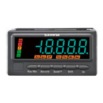
1.5 COMPONENT IDENTIFICATION ■ FRONT VIEW COMPONENT FUNCTION Infrared interface Used to configure parameters with a PC using PC Configurator Software (model: 47DCFG) and Infrared Communication Adaptor (model: COP-IRU). (Refer to 31. CONFIGURING PARAMETERS VIA INFRARED COMMUNICA- TION.) Display Engineering unit sticker label position BUTTON FUNCTION... - Page 15 ■ DISPLAY COMPONENT FUNCTION Main display Indicates present, MAX and MIN values, parameters, setting values and error codes. COMPONENT FUNCTION COMPONENT FUNCTION Bargraph Indicates present signal level against the Sub display Indicates the present parameter ID, alarm scaled range. 20 LED segments divided by setpoints and bank No., or over- or under- 10.
- Page 16 • The tag No. label sticker position is our recommended position. • When a tag No. is specified, the unit(s) will be shipped with the tag No. sticker label put on the above position. Max. 17 alphanumeric characters can be specified. Please consult M-System’s Hotline. 47DV OPERATING MANUAL EM-9501-B Rev.9...
- Page 17 ■ REAR VIEW • With Terminal Cover Connection diagram Terminal cover Strap Model No. NOTE • The connection diagram depends on the specifications. • The MODEL shows the same as that in the specification label on the top of the unit. •...
-
Page 18: Installation
1.6 INSTALLATION 1.6.1 EXTERNAL DIMENSIONS unit: mm (inch) TOP VIEW 95 (3.74) FRONT VIEW SIDE VIEW 103 (4.06) 98.5 (3.88) 96 (3.78) 12.5 (.49) 86 (3.39) 2 (.08) REAR VIEW 10–M3 SCREW 20–M3 SCREW • Alarm Output, RS-485 / Modbus •... -
Page 19: Panel Cutout Dimensions
1.6.2 PANEL CUTOUT DIMENSIONS + 0.8 unit: mm – 0 min. 120 Panel thickness: 1.6 to 8.0 mm 1.6.3 VIEWING ANGLE The display is designed to provide the optimal legibility when viewed from the angles as shown below. 47DV OPERATING MANUAL EM-9501-B Rev.9... -
Page 20: Installation
1.6.4 INSTALLATION (1) Remove the terminal cover. (a) Insert the minus tip of a screwdriver into a hole at the lower left corner of the cover. (b) Pull the handle upward. (c) Then insert the screwdriver into a hole at the lower right corner. (d) Pull the handle upward to separate the terminal cover. - Page 21 (4) Make sure that the watertight packing is placed behind the front cover regardless of necessity of water-tightness. Watertight packing (5) Insert the unit into the panel cutout. Panel Watertight packing (6) Push the mounting brackets into the grooves on both sides of the rear module, until they hit the panel’s rear side. Panel Bracket Fixing groove...
-
Page 22: Wiring Instructions
• Be sure to confirm the name and polarity of each terminal before wiring to it. • Do not connect anything to unused terminals. • M-System offers a series of lightning surge protectors for protection against induced lightning surges. Please contact M- System to choose appropriate models. - Page 23 ■ EVENT TRIGGER INPUT AND ALARM OUTPUT (PHOTO MOSFET RELAY) • APPLICABLE WIRE SIZE Solid: 0.5 to 1.25 mm (max. 1.3 dia.) Stranded: 0.5 to 1.25 mm (max. 1.3 dia.) 7 to 8 mm IMPORTANT • Tinning wire ends may cause contact failure and therefore is not recommended. •...
-
Page 24: Terminal Assignment
1.7.3 TERMINAL ASSIGNMENT ■ NO OPTIONS ■ ALARM OUTPUT, RS-485 / MODBUS Input signal Excitation DC output Power Input signal Excitation DC output Power RS-485/Modbus Alarm output ■ BCD OUTPUT, EVENT TRIGGER INPUT, ALARM OUTPUT (PHOTO MOSFET RELAY) Input signal Excitation DC output Power... -
Page 25: Wiring Input Signal
1.7.4 WIRING INPUT SIGNAL Connect DC voltage or current signal wires. Be careful that the input terminal assignment depends on the input code and type. IMPORTANT • Be sure to confirm the input polarity in wiring. Wrong connection may result in malfunction of the unit. •... -
Page 26: Wiring Excitation Supply
1.7.5 WIRING EXCITATION SUPPLY +12 V or +24 V voltage is output depending on the specified excitation supply code. CODE OUTPUT VOLTAGE CURRENT RATING SHORTCIRCUIT PROTECTION CURRENT LIMITED PROTECTED TIME DURATION 12 – 16 V DC with no load ≤ 84 mA DC 90 mA max. - Page 27 ■ CONNECTION EXAMPLES (1) 2-WIRE • For use with a two-wire transmitter • For use with a smart transmitter +24 V +24 V 10 Ω 1 – 5 V COM– – COM– – 250 Ω 4 – 20 mA 4 – 20 mA 2-Wire XMTR Smart transmitter * Choose DC voltage input (model: 47DV-1x2x-xx).
- Page 28 (2) 3-WIRE • For DC voltage input • For DC current input 0 – 10 V, +24 V (+12V) 10 Ω etc. +24 V (+12V) 1 – 5 V, 0 – 5 V, etc. COM– – COM– – 4 – 20 mA –...
-
Page 29: Wiring Dc Output
1.7.6 WIRING DC OUTPUT Voltage or current signal is output. IMPORTANT • Connect load resistance within the specifications. • Do not connect anything with no-DC-output type. • Take measures to reduce noise as much as possible, e.g. by using shielded twisted pair wires for the output signal. Ground the output shield to the most stable earth to prevent noise troubles. -
Page 30: Wiring Alarm Output (Relay)
1.7.7 WIRING ALARM OUTPUT (RELAY) Two or four alarm contacts are output depending on the specified I/O option code. IMPORTANT • Connect load within the specifications. • The mechanical lifetime of the relays is 5,000,000 operations. • With inductive load such as an external relay or a motor, insert a CR circuit (for AC or DC power), a diode (for DC power) or a varistor (for AC or DC power) in parallel to protect the contacts and eliminate noise. -
Page 31: Wiring Alarm Output (Photo Mosfet Relay)
1.7.8 WIRING ALARM OUTPUT (PHOTO MOSFET RELAY) Four alarm contacts are output. IMPORTANT • Connect load within the specifications. • With inductive load such as an external relay or a motor, insert a CR circuit (for AC or DC power), a diode (for DC power) or a varistor (for AC or DC power) in parallel to protect the contacts and eliminate noise. -
Page 32: Wiring Network Interface
1.7.9 WIRING NETWORK INTERFACE Writing/reading each measured value and configurations is available with a PC or PLC via Modbus communication. Transmission Half-duplex, asynchronous, no procedure Interface Conforms to TIA/EIA-485-A Max. transmission distance 500 meters Baud rate 1200, 2400, 4800, 9600, 19200, 38400 bps Protocol Modbus-RTU Node address... - Page 33 NOTE Refer to the connection diagram as shown below to wire triplex shield cables. HOST PC RS-485 47Dx 47Dx RS-485 Remote Unit RS-485 Terminator TX+/RX+ TX–/RX– Terminator RX– * Connect terminating resistors at both ends of the transmission line. When the 47DV is located at the end, close across the terminals T2 and T3 with a leadwire.
-
Page 34: Wiring Bcd Output
1.7.10 WIRING BCD OUTPUT BCD data in 6 digits and 5 alarm contacts including the P status are output. SIGNAL ID ITEM RATING Input REQ, MIN_REQ, MAX_REQ, HOLD, RESET Input signals Dry contact or NPN open collector Input current ≤ 3 mA Sensing Contact detecting ≤... - Page 35 I/O options code: 5, 9, A 6th LSD Do68 Do64 Do62 Do61 3rd LSD 2nd LSD 1st LSD Do38 Do34 Do32 Do31 Do28 Do24 Do22 Do21 Do18 Do14 Do12 Do11 Do58 Do52 Do48 Do42 Do54 Do51 Do44 Do41 5th LSD 4th LSD RESET HOLD...
- Page 36 ■ BCD OUTPUT CONNECTION EXAMPLES • Connected to a digital display • Connected to a PLC Digital Panel Meter +24 V DC Power Supply +6 V Digital Panel Meter shortcircuit 2 kΩ +6 V PLC Transistor Output Unit 1.5 kΩ 2 kΩ...
-
Page 37: Wiring Event Trigger Input
1.7.11 WIRING EVENT TRIGGER INPUT Control contacts are input. SIGNAL ID ITEM RATING TIMING Event trigger input Dry contact or NPN open collector S-TMR Input current ≤ 3 mA HOLD Sensing RESET ZERO Contact detecting ≤ 1.5 V at ON; ≥ 3 V at OFF Detecting time ≥... -
Page 38: Wiring Power
1.7.12 WIRING POWER Connect power according to the power input code. The power specifications are shown in the following table. CODE RATING PERMISSIBLE RANGE 100 to 240 V AC 85 to 264 V AC, 50/60 Hz Max. 12 VA 24 V DC ±10% approx. -
Page 39: Installing/Separating Terminal Block
1.7.13 INSTALLING/SEPARATING TERMINAL BLOCK ■ INPUT, EXCITATION SUPPLY, DC OUTPUT, ALARM OUTPUT (RELAY), NETWORK INTERFACE AND POWER INPUT The terminal block is separable in two pieces. Tighten (loosen) uniformly two screws on both sides of the terminal block to install (separate). Torque: 0.6 N∙m IMPORTANT Be sure to turn off the power supply, input signal and power supply to the output relays before installing/separating the... - Page 40 ■ BCD OUTPUT Insert the connector for the BCD output through the terminal cover opening until it clicks into place. Press the unlocking buttons on the right and left sides of the connector to remove. IMPORTANT Be sure to turn off the power supply, input signal and power supply to the output relays before installing/separating the connector.
-
Page 41: Attaching/Removing Terminal Cover
1.7.14 ATTACHING/REMOVING TERMINAL COVER Be sure to put the terminal cover on for safety after wiring. ■ ATTACHING TERMINAL COVER Fit the convex part A of the meter in the concave part B of the terminal cover and push the cover until it clicks into place. Terminal cover ■... -
Page 42: Basic Setting And Operation
2. BASIC SETTING AND OPERATION 2.1 BASIC SETTING This section describes flow and procedure of the basic setting. The following shows the flow and procedure to set the input to 0 – 10 V DC and the display to 0.00 – 1000.00 m with the input code ‘1’... -
Page 43: Basic Setting Procedure
2.1.3 BASIC SETTING PROCEDURE The following shows the procedure to set the input to 0 – 10 V DC and the display to 0.00 – 1000.00 m with the input code ‘1’ as an example. Set values meeting signals of an equipment to use. Refer to 3. SETTING INPUT TYPE for details of setting. -
Page 44: Basic Setting Operation And Instructions
2.2 BASIC SETTING OPERATION AND INSTRUCTIONS This section describes basic operation and instructions when setting parameters. 2.2.1 BASIC SETTING OPERATION Parameters can be grouped into three setting types, “numerical value setting” , “setting value selection” and “decimal point position selection” . Basic operation of each type is as shown below. ■... - Page 45 ■ SETTING VALUE SELECTION Press Shift button to shift the display into the setting standby mode. • The current set value starts blinking. Press Up button to select your desired setting value. Press Alarm/↓ or Scale/↑ button to apply the new setting. •...
-
Page 46: Instructions On Basic Operation
NOTE ■ MOVING THE DECIMAL POINT Pressing Up button moves the decimal point one place to the left. 4 decimal places (10 3 decimal places (10 2 decimal places (10 1 decimal place (10 No decimal point ■ DECIMAL POINT POSITION “No decimal point”... - Page 47 ■ IN MOVING ON TO EACH SETTING MODE FROM MEASURING MODE • The last measured values or status are held for the DC and alarm outputs, and the BCD output is indefinite. • Some alarm indicators turn on with parameter display. The alarm indication is due to the last status before mode transi- tion held but does not show the unit failure.
-
Page 48: Setting Input Type
3. SETTING INPUT TYPE Set input type according to the signal range of an input device to connect. Choose an input type so that the signal range of the device is the same as the measuring range of the input type or within the setting range. -
Page 49: Input Type List
3.1 INPUT TYPE LIST Input type can be changed within the same input code. ■ INPUT CODE: 1 [MODEL: 47DV-1XXX-XX] MAIN DISPLAY FUNCTION SETTING RANGE OPERATIONAL RANGE DEFAULT VALUE 1-5V Measuring range 1 – 5 V 1.0000 – 5.0000 V 0.6 –... -
Page 50: Operating Procedure
3.2 OPERATING PROCEDURE Procedures to change ‘1-5V’ (measuring range 1 – 5 V) (default) to ‘20V’ (measuring range -20 to +20 V) are described here. NOTE The left figure shows a display example (default value of input code ‘1’). The display depends on the and set- tings. - Page 51 Press Up button to select the input type. Blinking • Select ‘20V’ (measuring range -20 to +20 V). NOTE Refer to 3.1 INPUT TYPE LIST for selectable input types. Press Alarm/↓ or Scale/↑ button to apply the new setting. • And the next parameter setting is indicated. NOTE •...
-
Page 52: Setting Scaling Values
4. SETTING SCALING VALUES ■ INPUT SCALING Input scaling means setting an input value within the setting range of the selected input type. The input scaling values include Zero and Span. • Input scaling value Zero is minimum value (0%) of input signal. •... - Page 53 IMPORTANT • The bargraph lower and upper limits change according to changes of the display scaling values. The bargraph lower limit is reset to the same value as the display scaling value Zero, and the upper limit is reset to the same value as the display scaling value Span.
-
Page 54: Step 1. Input Scaling Value Zero
4.1 STEP 1. INPUT SCALING VALUE ZERO 4.1.1 INPUT SCALING LIST Input scaling default values and setting ranges per input code are as shown in the following tables. The input scaling values are reset to the default or the previously set values per input type when the input type has been changed. Set the values with 5 significant digits within the setting ranges, disregarding the decimal point. -
Page 55: Operating Procedure
4.1.2 OPERATING PROCEDURE NOTE 2,3, The left figure shows a display example (default value of input type ‘20V’). The display depends on the and set- tings. Refer to 4.1.1 INPUT SCALING LIST for details. Confirm the wiring, and turn on the power. Immediately after power on (all indicators on) •... - Page 56 Press Shift button to shift the display into the setting standby mode. Blinking • The sixth digit starts blinking, to which you can apply changes. • ‘Tch’ indicator turns off. Press Shift and Up buttons to set to ‘000.000’. Blinking •...
- Page 57 NOTE ■ INPUT SCALING SETTING • Do not set ‘input scaling value Zero ≥ input scaling value Span’ . ■ IF THE FRONT BUTTONS ARE LEFT UNTOUCHED… • The indication turns on with applying the last changes after the specified time period (default: 15 sec.) while it is in the setting standby mode (indication blinking in Step 4 and 5).
-
Page 58: Step 2. Display Scaling Value Zero
4.2 STEP 2. DISPLAY SCALING VALUE ZERO 4.2.1 DISPLAY SCALING LIST Display scaling default values and setting ranges per input code are as shown in the following tables. The display scaling values are reset to the default or the previously set values per input type when the input type has been changed. -
Page 59: Operating Procedure
4.2.2 OPERATING PROCEDURE NOTE 2,3, The left figure shows a display example (default value of input type ‘20V’). The display depends on the settings. Refer to 4.2.1 DISPLAY SCALING LIST for details. Confirm the wiring, and turn on the power. Immediately after power on (all indicators on) •... - Page 60 Press Shift button to shift the display into the setting standby mode. Blinking • The sixth digit starts blinking, to which you can apply changes. Press Shift and Up buttons to set to ‘000.000’. Blinking • Press Shift button to go to the next digit and Up button to change the blinking value.
- Page 61 NOTE ■ IF THE FRONT BUTTONS ARE LEFT UNTOUCHED… • The indication turns on with applying the last changes after the specified time period (default: 15 sec.) while it is in the setting standby mode (indication blinking in Step 4 and 5). •...
-
Page 62: Step 3. Input Scaling Value Span
4.3 STEP 3. INPUT SCALING VALUE SPAN 4.3.1 OPERATING PROCEDURE NOTE 2,3, The left figure shows a display example (default value of input type ‘20V’). The display depends on the settings. Refer to 4.1.1 INPUT SCALING LIST for details. Confirm the wiring, and turn on the power. Immediately after power on (all indicators on) •... - Page 63 Press Alarm/↓ or Scale/↑ button to go to the input scaling value Span setting. • The input scaling value Span is indicated. • The SD indicates ‘IN-B’ . • ‘Spn’ and ‘Tch’ indicators turn on. NOTE Skip to Step 7 if the default value is acceptable. Press Shift button to shift the display into the setting standby mode.
- Page 64 ■ TO GO ON TO SET THE DISPLAY SCALING VALUE SPAN, Skip to Step 3 in “4.4 STEP 4. DISPLAY SCALING VALUE SPAN” . ■ TO QUIT, Hold down Alarm/↓ or Scale/↑ button for 1 second or more to return to Measuring Mode. NOTE ■...
-
Page 65: Step 4. Display Scaling Value Span
4.4 STEP 4. DISPLAY SCALING VALUE SPAN 4.4.1 OPERATING PROCEDURE NOTE 2,3, The left figure shows a display example (default value of input type ‘20V’). The display depends on the settings. Refer to 4.2.1 DISPLAY SCALING LIST for details. Confirm the wiring, and turn on the power. Immediately after power on (all indicators on) •... - Page 66 Press Alarm/↓ or Scale/↑ button to go to the display scaling value Span setting. • The display scaling value Span is indicated. • The SD indicates ‘DISP-B’ . • ‘Spn’ indicator turns on. NOTE Skip to Step 7 if the default value is acceptable. Press Shift button to shift the display into the setting standby mode.
- Page 67 ■ TO GO ON TO SET THE DECIMAL POINT POSITION, Skip to Step 3 in “4.5 STEP 5. DECIMAL POINT POSITION” . ■ TO QUIT, Hold down Alarm/↓ or Scale/↑ button for 1 second or more to return to Measuring Mode. NOTE ■...
-
Page 68: Step 5. Decimal Point Position
4.5 STEP 5. DECIMAL POINT POSITION 4.5.1 DECIMAL POINT POSITION LIST Default values of decimal point position per input type are as shown in the following tables. The decimal point position is reset to the default or the previously set position per input type when the input type has been changed. -
Page 69: Operating Procedure
4.5.2 OPERATING PROCEDURE NOTE The left figure shows a display example (last 5 digits 2,3, of the set display scaling value Span). The display de- pends on the settings. Refer to 4.5.1 DECIMAL POINT POSITION LIST for details. Confirm the wiring, and turn on the power. Immediately after power on (all indicators on) •... - Page 70 Press Alarm/↓ or Scale/↑ button to go to the decimal point position setting. • The decimal point position is indicated. • The SD indicates ‘D-POINT’ . NOTE • The set display scaling value Span is indicated. When ‘100000’ is set, ‘00000’ (last 5 digits) is indicated. A negative sign is indicated.
- Page 71 ■ TO GO ON TO SET THE BARGRAPH TYPE, Skip to Step 2 in “7.1 BARGRAPH TYPE” . ■ TO QUIT, Hold down Alarm/↓ or Scale/↑ button for 1 second or more to return to Measuring Mode. NOTE ■ IF THE FRONT BUTTONS ARE LEFT UNTOUCHED… •...
-
Page 72: Operation
5. OPERATION Make sure that 0.00 - 1000.00 m is correctly indicated according to the input 0 – 10 V DC provided. The operation without using external control signals including the event trigger input is described here. IMPORTANT Before operating, make sure that the wiring is correct, the input and the power supply are within the specification range. Apply 0 V input (0%) and make sure that 0.00 m is indicated. -
Page 73: Parameter Configuration
6. PARAMETER CONFIGURATION ■ MODE Parameters can be grouped in several modes. The 47DV has modes as shown in the following table. MODE FUNCTION MEASUREMENT Measuring Normal measurement state where the unit takes in input and provides alarms. Measuring Present value, MAX and MIN values can be indicated, and alarm setpoints can be indicated and set in Measuring Mode. - Page 74 ■ MODE TRANSITION May be disabled depending on the model suffix codes. Indicated regardless of the model suffix codes. POWER ON Hold down Max/Min + Alarm/↓ Measuring Hold down Alarm/↓ + Scale/↑ + Shift Mode at once for a preset at once for ≥...
- Page 75 ■ SHIFTING THROUGH SETTING PARAMETERS (1) Parameter shifting in Scaling Setting Mode In Scaling Setting Mode, pressing Alarm/↓ button shifts one parameter to the next (clockwise in the following figure). Press- ing Scale/↑ button shifts one to the previous (counterclockwise). Hold down Scale/↑...
- Page 76 (2) Parameter shifting in Alarm Setting Mode In Alarm Setting Mode, pressing Alarm/↓ button shifts one parameter to the next (clockwise in the following figure). Press- ing Scale/↑ button shifts one to the previous (counterclockwise). Hold down Alarm/↓ for ≥ 3 sec. Measuring Mode Alarm Setting Mode Bank No.
- Page 77 Continued from the previous page Continued from the previous page HH trip action L OFF delay time HH alarm setpoint L one-shot output H coil at alarm L coil at alarm H one-shot output H alarm setpoint H OFF delay time H trip action H ON delay time H deadband (hysteresis)
- Page 78 (3) Parameter shifting in Advanced Setting Mode In Advanced Setting Mode, pressing Alarm/↓ button shifts one parameter to the next (clockwise in the following figure). Pressing Scale/↑ button shifts one to the previous (counterclockwise). Hold down Alarm/↓ + Scale/↑ at once for ≥ 3 sec. Measuring Mode Advanced Setting Mode Event trigger mode...
- Page 79 Continued from the previous page Continued from the previous page Scaling error Manual sub display reset Standby sequence P output Alarm power ON delay Latching alarm *1 Enabled with the I/O option code ‘6’ or ‘A’ (event tripper input). *2 Disabled with “normal” selected for the event trigger mode parameter. *3 Disabled with “normal”...
- Page 80 (5) Parameter shifting in Infrared Communication Mode There is no parameter shifting in this mode. (6) Parameter shifting in Lockout Setting Mode In Lockout Setting Mode, pressing Alarm/↓ button shifts one parameter to the next (clockwise in the following figure). Pressing Scale/↑...
-
Page 81: Setting Bargraph
7. SETTING BARGRAPH A bargraph with 20 segments divided by 10 is in the left on the display, which shows the signal level of the indicated value (present, MAX or MIN value) against the scaled range. The bargraph range is set with the bargraph lower and upper limits. The bargraph type can be selected among those shown in the following table. - Page 82 ■ SETTING RANGE OF BARGRAPH LOWER AND UPPER LIMITS The bargraph lower and upper limits can be set within the range of -20000 to 100000. The default values per input type are as shown in the following tables. • INPUT CODE: 1 [MODEL: 47DV-1XXX-XX] INPUT TYPE DEFAULT VALUE (MAIN DISPLAY)
-
Page 83: Bargraph Type
7.1 BARGRAPH TYPE 7.1.1 OPERATING PROCEDURE 1,2, NOTE The following figures are display examples. The displays depend on the specifications and settings. Hold down Scale/↑ button for 3 seconds or more to move on to Scaling Setting Mode. • The input type is indicated. •... - Page 84 ■ TO GO ON TO SET THE BARGRAPH LOWER LIMIT/UPPER LIMIT, Skip to Step 2 in “7.2 BARGRAPH LOWER LIMIT/UPPER LIMIT” . ■ TO QUIT, Hold down Alarm/↓ or Scale/↑ button for 1 second or more to return to Measuring Mode. 47DV OPERATING MANUAL EM-9501-B Rev.9...
-
Page 85: Bargraph Lower Limit/Upper Limit
7.2 BARGRAPH LOWER LIMIT/UPPER LIMIT 7.2.1 OPERATING PROCEDURE 2,4, 1,2, NOTE The following figures are display examples. The displays depend on the specifications and settings. Hold down Scale/↑ button for 3 seconds or more to move on to Scaling Setting Mode. •... - Page 86 Press Shift button to shift the display into the setting standby mode. Then press Shift and Up buttons to set the bargraph Blinking upper limit. • The sixth digit starts blinking, to which you can apply changes. • Set within the range of -20000 to 100000. NOTE Set the bargraph upper limit with the decimal point position set in the decimal point position setting.
-
Page 87: Setting Analog Output
8. SETTING ANALOG OUTPUT The DC current or voltage output can be selected among those shown in Table 1. The analog outputs 0% and 100% can be set within the range of -20000 to 100000. Also the analog output function, “proportional to the display value” as shown in Figure 1 or “proportional to the scaling value”... - Page 88 ■ SETTING RANGE OF ANALOG OUTPUTS 0% AND 100% The analog outputs 0% and 100% can be set within the range of -20000 to 100000. The default values per input type are as shown in the following tables. • INPUT CODE: 1 [MODEL: 47DV-1XXX-XX] INPUT TYPE DEFAULT VALUE (MAIN DISPLAY)
-
Page 89: Analog Output Type
8.1 ANALOG OUTPUT TYPE 8.1.1 OPERATING PROCEDURE 1,2, NOTE The following figures are display examples. The displays depend on the specifications and settings. Hold down Scale/↑ button for 3 seconds or more to move on to Scaling Setting Mode. • The input type is indicated. •... - Page 90 ■ TO GO ON TO SET THE ANALOG OUTPUT FUNCTION MODE, Skip to Step 2 in “8.2 ANALOG OUTPUT FUNCTION MODE” . ■ TO QUIT, Hold down Alarm/↓ or Scale/↑ button for 1 second or more to return to Measuring Mode. 47DV OPERATING MANUAL EM-9501-B Rev.9...
-
Page 91: Analog Output Function Mode
8.2 ANALOG OUTPUT FUNCTION MODE 8.2.1 OPERATING PROCEDURE 1,2, NOTE The following figures are display examples. The displays depend on the specifications and settings. Hold down Scale/↑ button for 3 seconds or more to move on to Scaling Setting Mode. •... - Page 92 ■ TO GO ON TO SET THE ANALOG OUTPUTS 0% AND 100%, Skip to Step 2 in “8.3 ANALOG OUTPUT 0% / ANALOG OUTPUT 100%” . ■ TO QUIT, Hold down Alarm/↓ or Scale/↑ button for 1 second or more to return to Measuring Mode. 47DV OPERATING MANUAL EM-9501-B Rev.9...
-
Page 93: Analog Output 0% / Analog Output 100
8.3 ANALOG OUTPUT 0% / ANALOG OUTPUT 100% 8.3.1 OPERATING PROCEDURE 2,4, 1,2, NOTE The following figures are display examples. The displays depend on the specifications and settings. Hold down Scale/↑ button for 3 seconds or more to move on to Scaling Setting Mode. - Page 94 Press Shift button to shift the display into the setting standby mode. Then press Shift and Up buttons to set the analog out- Blinking put 100%. • The sixth digit starts blinking, to which you can apply changes. • Set within the range of -20000 to 100000. NOTE Set the analog output 100% with the decimal point position set in the decimal point position setting.
-
Page 95: Basic Alarm Setting
9. BASIC ALARM SETTING The alarm output configuration includes “basic setting” to configure basic parameters such like alarm output pattern, alarm setpoints, trip action, ON and OFF delay time and coil at alarm, “bank” to save max. 8 sets of setpoints to switch as neces- sary, and “advanced setting”... - Page 96 ■ ALARM ACTION BASICS Alarm trip operates in relation to the display value. Alarm indicators, except for ‘P’ indicator, do not turn on until all param- eters (display value, deadband, ON delay time elapsed) of the setpoint become true. Display color is switched accordingly with “green (normal) to red (alarm)”...
- Page 97 Figure 4: All trip points set to high setting (normal setting) Figure 5: Deadband (hysteresis) Display value Display value HH alarm setpoint H alarm setpoint L alarm setpoint LL alarm setpoint Closeup HH alarm output (hi) H alarm output (hi) L alarm output (hi) Alarm setpoint (hi) Display value...
- Page 98 Figure 8: One-shot output Without event trigger input or with event trigger mode set With event trigger mode set to other than “normal” to “normal” e.g. Sampling hold H alarm setpoint H alarm setpoint Display value Display value ‘H’ indicator TIMING signal ‘H’...
-
Page 99: Alarm Output Pattern
9.1 ALARM OUTPUT PATTERN The alarm output pattern, normal output (‘NORMAL’) where alarm trips according to the setpoint, or zone output (‘ZONE’) where alarm trips and resets between each setpoint, can be selected. The default setting is normal output. IMPORTANT •... -
Page 100: Operating Procedure
9.1.1 OPERATING PROCEDURE NOTE The following figures are display examples. The displays depend on the settings. Hold down Alarm/↓ button for 3 seconds or more to move on to Alarm Setting Mode. • The alarm output pattern is indicated. • The SD indicates ‘ A LM PTN’ . NOTE With the bank switching set to “enabled via the front button control”... -
Page 101: Alarm Setpoint
9.2 ALARM SETPOINT Alarm setpoints can be set within the range of -20000 to 100000. However the alarm is not provided in setting the setpoint beyond the operational range of the input type. Set the setpoints within the valid range. All alarm setpoints of the current bank No. -
Page 102: Operating Procedure
9.2.2 OPERATING PROCEDURE Blinking 1,2, NOTE The following figures are display examples. The displays depend on the settings. Hold down Alarm/↓ button for 3 seconds or more to move on to Alarm Setting Mode. • The alarm output pattern is indicated. •... - Page 103 Press Alarm/↓ or Scale/↑ button to apply the new setting. • And the next parameter setting is indicated. NOTE • Press Alarm/↓ button, and the L (H or HH) alarm setpoint (‘ A LARM L’ , ‘ A LARM H’ or ‘ A LARMHH’ on the SD), or the display blinking at alarm (‘...
-
Page 104: Trip Action (Lo/Hi)
9.3 TRIP ACTION (LO/HI) The trip action low ‘LOW’ or high ‘HIGH’ can be selected. Configuring typical L/H trip setting or all trip points to high or low setting is available. The default values are “low trip” for the LL and L trip actions and “high trip” for the HH and H. NOTE This setting is disregarded with the alarm output pattern set to “ZONE”... - Page 105 Press Alarm/↓ or Scale/↑ button to apply the new setting. • And the next parameter setting is indicated. NOTE • Press Alarm/↓ button, and the LL (L, H or HH) deadband will be indicated (‘HYST LL’ , ‘HYST L’ , ‘HYST H’ or ‘HYST HH’ on the SD).
-
Page 106: Deadband
9.4 DEADBAND Once a high (low) trip alarm is ON, the alarm stays ON until the data becomes lower (higher) than a certain range from the setpoint, which prevents the alarm output from chattering when the display value fluctuates slightly near the setpoint. This range is called deadband (hysteresis) and can be set within the range of 0000 to 9999. - Page 107 Press Alarm/↓ or Scale/↑ button to apply the new setting. • And the next parameter setting is indicated. NOTE • Press Alarm/↓ button, and the LL (L, H or HH) ON delay time will be indicated (‘ONDLYLL’ , ‘ONDLY L’ , ‘ONDLY H’ or ‘ONDLYHH’...
-
Page 108: On Delay Time
9.5 ON DELAY TIME Alarm output is provided when the display value exceeds the setpoint and stayed for the specified time duration, which prevents the alarm output from being provided by a sudden change such like external disturbance and starting current. This time duration is called ON delay time and can be set within the range of 0.0 to 99.9 seconds. - Page 109 Press Alarm/↓ or Scale/↑ button to apply the new setting. • And the next parameter setting is indicated. NOTE • Press Alarm/↓ button, and the LL (L, H, HH or P) OFF delay time will be indicated (‘OFDLYLL’ , ‘OFDLY L’ , ‘OFDLY H’ , ‘OFDLYHH’...
-
Page 110: Off Delay Time
9.6 OFF DELAY TIME Alarm output is canceled when the display value returns to the value to cancel the alarm and stays for the specified time duration, which prevents the alarm output from being canceled by a rapid or sudden change such like external disturbance. This time duration is called OFF delay time and can be set within the range of 0.0 to 99.9 seconds. - Page 111 Press Shift button to shift the display into the setting standby mode. Then press Shift and Up buttons to set the LL (L, H, HH Blinking or P) OFF delay time. • The third digit starts blinking, to which you can apply changes. •...
-
Page 112: One-Shot Output
9.7 ONE-SHOT OUTPUT Alarm outputs can be provided as one-shot pulses. The one-shot output can be set within the range of 0.1 to 999.9 sec- onds. Set 0000 to provide normal contact outputs. The default value is 0000. The one-shot output is configurable also for the P status. - Page 113 Press Shift button to shift the display into the setting standby mode. Then press Shift and Up buttons to set the LL (L, H, HH Blinking or P) one-shot output. • The forth digit starts blinking, to which you can apply changes. •...
-
Page 114: Alarm Output Logic (Coil Energized Or De-Energized At Alarm)
9.8 ALARM OUTPUT LOGIC (coil energized or de-energized at alarm) Alarm output logic can be selected. This parameter is called energizing direction and coil energized ‘EN’ or de-energized ‘DE’ at alarm can be selected. In selecting coil de-energized at alarm, the alarm output logic is inverted. The default set- ting is coil energized. - Page 115 Press Alarm/↓ or Scale/↑ button to apply the new setting. • And the next parameter setting is indicated. NOTE • Press Alarm/↓ button, and the L (H or HH) setpoint (‘ A LARM L’ , ‘ A LARM H’ or ‘ A LARMHH’ on the SD), P ON delay time (‘ONDLY P’...
-
Page 116: Main Display Blinking At Alarm
9.9 MAIN DISPLAY BLINKING AT ALARM Main display blinking interval at alarm can be specified. The interval can be selected among those shown in the following table. ■ BLINKING INTERVAL AT ALARM MAIN DISPLAY FUNCTION DEFAULT VALUE No blinking Blinking in 1.0 second intervals Blinking in 0.5 second intervals Blinking in 0.3 second intervals 9.9.1 OPERATING PROCEDURE... - Page 117 Press Shift or Up button to select the main display blinking at alarm. Blinking • Select one among ‘0’ , ‘1’ , ‘2’ and ‘3’ . Press Alarm/↓ or Scale/↑ button to apply the new setting. • And the next parameter setting is indicated. NOTE •...
-
Page 118: Bank Setting
10. BANK SETTING The 47DV has 8 areas (banks) to save a set of preset alarm setpoints. Switching them enables the setpoints to be changed easily. This bank switching can be “enabled via the front button control” or “enabled via Modbus communication” (Table 1). -
Page 119: Bank Switching
10.1 BANK SWITCHING 10.1.1 OPERATING PROCEDURE 1,2, 2,4, NOTE The following figures are display examples. The displays depend on the specifications and settings. Hold down Alarm/↓ and Scale/↑ buttons at once for 3 seconds or more to move on to Advanced Setting Mode. •... - Page 120 Press Alarm/↓ or Scale/↑ button to apply the new setting. • And the next parameter setting is indicated. NOTE • Press Alarm/↓ button, and the firmware version indication will be indicated (‘FRM-VER’ on the SD), or the REQ input logic will be indicated (‘BCD-REQ’ on the SD) with the I/O option code ‘5’ , ‘9’ or ‘ A ’ . •...
-
Page 121: Bank Copy
10.2 BANK COPY 10.2.1 OPERATING PROCEDURE 1,2, NOTE The following figures are display examples. The displays depend on the settings. Hold down Alarm/↓ button for 3 seconds or more to move on to Alarm Setting Mode. • The bank No. is indicated. •... - Page 122 ■ TO GO ON TO SET THE BANK NO., Skip to Step 2 in “10.3 BANK NO.” . ■ TO QUIT, Hold down Alarm/↓ or Scale/↑ button for 1 second or more to return to Measuring Mode. 47DV OPERATING MANUAL EM-9501-B Rev.9...
-
Page 123: Bank No
10.3 BANK NO. 10.3.1 OPERATING PROCEDURE NOTE The following figures are display examples. The displays depend on the settings. Hold down Alarm/↓ button for 3 seconds or more to move on to Alarm Setting Mode. • The bank No. is indicated. •... -
Page 124: Advanced Alarm Setting
11. ADVANCED ALARM SETTING Advanced alarm operation can be set. You can configure parameters as shown in Tables 1 and 2. Figures 1 to 4 show alarm examples. ■ TABLE 1: ADVANCED ALARM OUTPUT PARAMETERS PARAMETER FUNCTION P output Alarm outputs are normally assigned to the LL, L, H and HH alarms and there is not an output for the P status. - Page 125 Figure 1: P output ■ P OUTPUT ASSIGNED TO H ALARM OUTPUT Display value HH alarm setpoint H alarm setpoint L alarm setpoint LL alarm setpoint HH alarm output (hi) H alarm output (hi) L alarm output (lo) LL alarm output (lo) ‘HH’...
- Page 126 Figure 3: Alarm power ON delay Figure 4: Standby sequence Display value Display value L alarm setpoint L alarm setpoint Alarm power ON delay time Alarm power ON delay time L alarm output (lo) ‘P’ indicator L Alarm output (lo) ‘L’...
-
Page 127: P Output
11.1 P OUTPUT Alarm outputs are normally assigned to the LL, L, H and HH alarms and there is not an output for the P status. However the P output can be assigned to an output instead of one of them. The default setting is “no P output” . NOTE •... - Page 128 Press Shift and Up buttons to select the P output. Blinking • Select one among ‘OFF’ , ‘LL’ , ‘L’ , ‘H’ and ‘HH’ . Blinking NOTE An alarm indicator blinks corresponding to the setting. Press Alarm/↓ or Scale/↑ button to apply the new setting. •...
-
Page 129: Latching Alarm
11.2 LATCHING ALARM The alarm output ON except for the P output can be held, which is called latching alarm. “Output latched / measuring con- tinued” (‘OUT’) or “output latched / measuring stopped” (‘ A LL’) can be selected. In order to reset the latching, set the latch- ing alarm to “no latching”... - Page 130 Press Alarm/↓ or Scale/↑ button to apply the new setting. • And the next parameter setting is indicated. NOTE • Press Alarm/↓ button, and the alarm power ON delay will be indicated (‘PWR-DLY’ on the SD). • Press Scale/↑ button, and the P output will be indicated (‘PASS’ on the SD). Hold down Alarm/↓...
-
Page 131: Alarm Power On Delay
11.3 ALARM POWER ON DELAY The measuring can begin after waiting for the delay time from power on. This time duration is called alarm power ON delay and can be set within the range of 0.0 to 999.9 seconds. The default value is 0.0 second. IMPORTANT The changes on this setting are effective after power off and restart. - Page 132 Press Alarm/↓ or Scale/↑ button to apply the new setting. • And the next parameter setting is indicated. NOTE • Press Alarm/↓ button, and the standby sequence will be indicated (‘STDBY’ on the SD). • Press Scale/↑ button, and the latching alarm will be indicated (‘OUT-STP’ on the SD). Hold down Alarm/↓...
-
Page 133: Standby Sequence
11.4 STANDBY SEQUENCE The alarm and DC outputs can stand by until the input enters P zone from power on, which is called standby sequence. “Output immediately at the startup” (‘OFF’) or “output standing by until the input enters P zone” (‘ON’) can be selected. The default setting is “output immediately at the startup”... - Page 134 Press Alarm/↓ or Scale/↑ button to apply the new setting. • And the next parameter setting is indicated. NOTE • Press Alarm/↓ button, and the scaling error will be indicated (‘SE-ALM’ on the SD). • Press Scale/↑ button, and the alarm power ON delay will be indicated (‘PWR-DLY’ on the SD). Hold down Alarm/↓...
-
Page 135: Alarm Trip Action At Over-Range
11.5 ALARM TRIP ACTION AT OVER-RANGE The alarm trip action while ‘S.ERR’ is indicated can be set with the scaling error parameter. When it is set to “alarm trip ac- tion valid at over-range” (‘ON’), a high or low alarm output is provided depending on the ‘S.ERR’ direction. When set to “no alarm trip action at over-range”... - Page 136 Press Alarm/↓ or Scale/↑ button to apply the new setting. • And the next parameter setting is indicated. NOTE • Press Alarm/↓ button, and the round off low-digit reading will be indicated (‘STEP’ on the SD). • Press Scale/↑ button, and the standby sequence will be indicated (‘STDBY’ on the SD). Hold down Alarm/↓...
-
Page 137: Averaging Input
12. AVERAGING INPUT Moving or simple average processing of measured values is configurable (Table 1). Figures 1 and 2 show the difference of the moving average and simple average. The number of samples in averaging can be selected in Table 2. ■... - Page 138 ■ TABLE 2: AVERAGING TIME MAIN DISPLAY FUNCTION DEFAULT VALUE No averaging 2 samples (100 millisecond intervals) 4 samples (200 millisecond intervals) 8 samples (400 millisecond intervals) 16 samples (800 millisecond intervals) 32 samples (1.6 second intervals) 64 samples (3.2 second intervals) 128 samples (6.4 second intervals) 256 samples (12.8 second intervals) 512 samples (32.6 second intervals)
-
Page 139: Averaging Type
12.1 AVERAGING TYPE 12.1.1 OPERATING PROCEDURE NOTE The following figures are display examples. The displays depend on the specifications and settings. Hold down Alarm/↓ and Scale/↑ buttons at once for 3 seconds or more to move on to Advanced Setting Mode. •... - Page 140 ■ TO GO ON TO SET THE AVERAGING TIME, Skip to Step 2 in “12.2 AVERAGING TIME” . ■ TO QUIT, Hold down Alarm/↓ or Scale/↑ button for 1 second or more to return to Measuring Mode. 47DV OPERATING MANUAL EM-9501-B Rev.9...
-
Page 141: Averaging Time
12.2 AVERAGING TIME 12.2.1 OPERATING PROCEDURE 1,2, 1,2, NOTE The following figures are display examples. The displays depend on the specifications and settings. Hold down Alarm/↓ and Scale/↑ buttons at once for 3 seconds or more to move on to Advanced Setting Mode. •... - Page 142 Press Alarm/↓ or Scale/↑ button to apply the new setting. • And the next parameter setting is indicated. NOTE • Press Alarm/↓ button, and the low-end cutout will be indicated (‘ZEROLMT’ on the SD). • Press Scale/↑ button, and the averaging type will be indicated (‘ A VE-TP’ on the SD). Hold down Alarm/↓...
-
Page 143: Eliminating Fluctuation Around "0
13. ELIMINATING FLUCTUATION AROUND “0” A measured value less than the preset cutout value can be forcibly cut to 0 (figures below). This parameter is called low- end cutout and the value is called low-end cutout value. Enable the low-end cutout first and set the low-end cutout value within the range of 000 to 999. -
Page 144: Low-End Cutout
13.1 LOW-END CUTOUT 13.1.1 OPERATING PROCEDURE 1,2, 1,2, NOTE The following figures are display examples. The displays depend on the specifications and settings. Hold down Alarm/↓ and Scale/↑ buttons at once for 3 seconds or more to move on to Advanced Setting Mode. •... - Page 145 Press Alarm/↓ or Scale/↑ button to apply the new setting. • And the next parameter setting is indicated. NOTE • Press Alarm/↓ button, and the low-end cutout value will be indicated (‘ZLMTN’ on the SD), or the display color will be indicated (‘COLOR’...
-
Page 146: Low-End Cutout Value
13.2 LOW-END CUTOUT VALUE 13.2.1 OPERATING PROCEDURE 1,2, 1,2, NOTE The following figures are display examples. The displays depend on the specifications and settings. Hold down Alarm/↓ and Scale/↑ buttons at once for 3 seconds or more to move on to Advanced Setting Mode. •... - Page 147 Press Alarm/↓ or Scale/↑ button to apply the new setting. • And the next parameter setting is indicated. NOTE • Press Alarm/↓ button, and the display color will be indicated (‘COLOR’ on the SD). • Press Scale/↑ button, and the low-end cutout will be indicated (‘ZEROLMT’ on the SD). Hold down Alarm/↓...
-
Page 148: Setting Display Color
14. SETTING DISPLAY COLOR The main display color red or green can be selected or switched. The display colors can be switched depending whether in each mode and in the P zone, or in alarm and error status. ■ DISPLAY COLOR MAIN DISPLAY FUNCTION DEFAULT VALUE... - Page 149 Press Shift and Up buttons to select the display color. Blinking • Select one among ‘GRN-R’ , ‘GRN’ , ‘RED-G’ and ‘RED’ . Press Alarm/↓ or Scale/↑ button to apply the new setting. • And the next parameter setting is indicated. NOTE •...
-
Page 150: Going Back Automatically To Measuring Mode
15. GOING BACK AUTOMATICALLY TO MEASURING MODE The display goes back automatically to Measuring Mode if the front buttons are left untouched for the specified time period while it is in one of the setting modes. This time period is called automatic return time and can be set within the range of 1 to 99 seconds (Table 1). -
Page 151: Operating Procedure
15.1 OPERATING PROCEDURE 1,2, 1,2, NOTE The following figures are display examples. The displays depend on the specifications and settings. Hold down Alarm/↓ and Scale/↑ buttons at once for 3 seconds or more to move on to Advanced Setting Mode. •... - Page 152 Press Alarm/↓ or Scale/↑ button to apply the new setting. • And the next parameter setting is indicated. NOTE • Press Alarm/↓ button, and the transition time to Lockout Setting Mode will be indicated (‘PROTECT’ on the SD). • Press Scale/↑ button, and the display color will be indicated (‘COLOR’ on the SD). Hold down Alarm/↓...
-
Page 153: Adjusting Display Refreshing Rate
16. ADJUSTING DISPLAY REFRESHING RATE The 47DV measures input signal at the read rate 50 milliseconds. The display refreshing rate can be slower than this rate (figure below) within the range of 0.1 to 99.9 seconds. With this value set to 00.0, the refreshing rate will be the same as the read rate (50 milliseconds) (table below). -
Page 154: Operating Procedure
16.1 OPERATING PROCEDURE 1,2, 1,2, NOTE The following figures are display examples. The displays depend on the specifications and settings. Hold down Alarm/↓ and Scale/↑ buttons at once for 3 seconds or more to move on to Advanced Setting Mode. •... - Page 155 Press Alarm/↓ or Scale/↑ button to apply the new setting. • And the next parameter setting is indicated. NOTE • Press Alarm/↓ button, and the firmware version indication will be indicated (‘FRM-VER’ on the SD), or the manual sub display reset will be indicated (‘S-DISP’ on the SD) with the alarm setting lockout set to “completely unlock Alarm Set- ting Mode”...
-
Page 156: Rounding Off Lowest Digit Reading
17. ROUNDING OFF LOWEST DIGIT READING Rounding off the lowest digit reading of the measured value can suppress variation in the display without setting the aver- aging processing or slowing the display refreshing rate. This round off low-digit reading can be selected among ‘OFF’ (1), ‘2’... -
Page 157: Operating Procedure
17.1 OPERATING PROCEDURE 1,2, 1,2, NOTE The following figures are display examples. The displays depend on the specifications and settings. Hold down Alarm/↓ and Scale/↑ buttons at once for 3 seconds or more to move on to Advanced Setting Mode. •... - Page 158 Press Alarm/↓ or Scale/↑ button to apply the new setting. • And the next parameter setting is indicated. NOTE • Press Alarm/↓ button, and the display reading type will be indicated (‘M-DISP’ on the SD). • Press Scale/↑ button, and the scaling error will be indicated (‘SE-ALM’ on the SD). Hold down Alarm/↓...
-
Page 159: Detecting Steep Input Changes
18. DETECTING STEEP INPUT CHANGES Only steep changes in the input signals can be detected with mild changes disregarded, which is called high-pass filter. Deviation between the currently measured input value and the average of the past values is calculated. Table 2 shows the relationship between the sampling time and the reading. - Page 160 ■ OPERATION WITH HIGH-PASS FILTER ON/OFF High-pass lter OFF High-pass lter ON 360° NOTE • When the high-pass filter is set to “ON” , the display scaling range is reset to the one with 0 as 50% regardless of the display scaling settings.
-
Page 161: Operating Procedure
18.1 OPERATING PROCEDURE 1,2, 1,2, NOTE The following figures are display examples. The displays depend on the specifications and settings. Hold down Alarm/↓ and Scale/↑ buttons at once for 3 seconds or more to move on to Advanced Setting Mode. •... - Page 162 Press Alarm/↓ or Scale/↑ button to apply the new setting. • And the next parameter setting is indicated. NOTE • Press Alarm/↓ button, and the backlight brightness will be indicated (‘BRIGHT’ on the SD). • Press Scale/↑ button, and the display reading type will be indicated (‘M-DISP’ on the SD). Hold down Alarm/↓...
-
Page 163: Adjusting Brightness Of Display
19. ADJUSTING BRIGHTNESS OF DISPLAY The backlight brightness can be adjusted (figures below). The brightness can be selected in the following table. ■ BACKLIGHT BRIGHTNESS MAIN DISPLAY FUNCTION DEFAULT VALUE Brightness level 1 (dark) Brightness level 2 Brightness level 3 (bright) ■... -
Page 164: Operating Procedure
19.1 OPERATING PROCEDURE 1,2, 1,2, NOTE The following figures are display examples. The displays depend on the specifications and settings. Hold down Alarm/↓ and Scale/↑ buttons at once for 3 seconds or more to move on to Advanced Setting Mode. •... - Page 165 Press Alarm/↓ or Scale/↑ button to apply the new setting. • And the next parameter setting is indicated. NOTE • Press Alarm/↓ button, and the LCD contrast will be indicated (‘CNTRAST’ on the SD). • Press Scale/↑ button, and the high-pass filter will be indicated (‘HP-F’ on the SD). Hold down Alarm/↓...
-
Page 166: Adjusting Lcd Contrast
20. ADJUSTING LCD CONTRAST The LCD contrast can be adjusted at 10 levels. The contrast can be selected in the following table. ■ LCD CONTRAST MAIN DISPLAY FUNCTION DEFAULT VALUE Contrast level 1 (low) Contrast level 2 Contrast level 3 Contrast level 4 Contrast level 5 (middle) Contrast level 6... -
Page 167: Operating Procedure
20.1 OPERATING PROCEDURE 1,2, 1,2, NOTE The following figures are display examples. The displays depend on the specifications and settings. Hold down Alarm/↓ and Scale/↑ buttons at once for 3 seconds or more to move on to Advanced Setting Mode. •... - Page 168 Press Alarm/↓ or Scale/↑ button to apply the new setting. • And the next parameter setting is indicated. NOTE • Press Alarm/↓ button, and the bank switching will be indicated (‘BNK-CHG’ on the SD). • Press Scale/↑ button, and the backlight brightness will be indicated (‘BRIGHT’ on the SD). Hold down Alarm/↓...
-
Page 169: Setting Event Trigger Input
21. SETTING EVENT TRIGGER INPUT External TIMING signals enable synchronous measurement, measurement of the MAX and MIN values and their deviation. The timing to start or finish the measurement can be adjusted with the TIMING signals. This section describes event trig- ger signals, modes and ON/OFF timing delay. - Page 170 • TABLE 2: TIMING SIGNAL V.S. S-TMR SIGNAL Sampling Hold Measuring Measuring Measuring disabled Measuring disabled TIMING S-TMR Other Measuring disabled Measuring (halt) Measuring disabled Measuring disabled TIMING S-TMR • TABLE 3: TIMING SIGNAL V.S. HOLD SIGNAL Sampling Hold Measuring Measuring Measuring Measuring disabled...
- Page 171 • TABLE 6: NORMAL MODE TIMING signal When the TIMING signal is ON, ‘TG’ indicator turns on, however the signal is invalid. Measures continuously. HOLD signal While the HOLD signal is ON, the display reading is held Scaling error range at the measured value at the falling edge of the signal, and the TIMING, S-TMR and ZERO signals are invalid.
- Page 172 • TABLE 10: PEAK-TO-PEAK HOLD MODE TIMING signal While the TIMING signal is ON, the difference between the MAX and MIN values with-in the period is measured Scaling error range and stored, and is established at the rising edge of the signal.
- Page 173 ■ ON TIMING DELAY/OFF TIMING DELAY Logical switching of the TIMING signal is delayed for the preset delay time from the physical signal change. After the preset ON/OFF timing delay, the measurement is started and the measured value is held, or the measurement is finished (Table 11).
-
Page 174: Event Trigger Mode
21.1 EVENT TRIGGER MODE 21.1.1 OPERATING PROCEDURE NOTE The following figures are display examples. The displays depend on the settings. Hold down Alarm/↓ and Scale/↑ buttons at once for 3 seconds or more to move on to Advanced Setting Mode. •... - Page 175 ■ TO GO ON TO SET THE ON TIMING DELAY, Skip to Step 2 in “21.2 ON TIMING DELAY” . ■ TO QUIT, Hold down Alarm/↓ or Scale/↑ button for 1 second or more to return to Measuring Mode. 47DV OPERATING MANUAL EM-9501-B Rev.9...
-
Page 176: On Timing Delay
21.2 ON TIMING DELAY 21.2.1 OPERATING PROCEDURE 1,2, 1,2, NOTE The following figures are display examples. The displays depend on the settings. Hold down Alarm/↓ and Scale/↑ buttons at once for 3 seconds or more to move on to Advanced Setting Mode. •... - Page 177 Press Alarm/↓ or Scale/↑ button to apply the new setting. • And the next parameter setting is indicated. NOTE • Press Alarm/↓ button, and the OFF timing delay will be indicated (‘OF-TDLY’ on the SD), or the startup timer will be indicated (‘STR-TMR’...
-
Page 178: Off Timing Delay
21.3 OFF TIMING DELAY 21.3.1 OPERATING PROCEDURE 1,2, 1,2, NOTE The following figures are display examples. The displays depend on the settings. Hold down Alarm/↓ and Scale/↑ buttons at once for 3 seconds or more to move on to Advanced Setting Mode. •... - Page 179 Press Alarm/↓ or Scale/↑ button to apply the new setting. • And the next parameter setting is indicated. NOTE • Press Alarm/↓ button, and the startup timer will be indicated (‘STR-TMR’ on the SD). • Press Scale/↑ button, and the ON timing delay will be indicated (‘ON-TDLY’ on the SD). ■...
-
Page 180: Startup Timer
21.4 STARTUP TIMER 21.4.1 OPERATING PROCEDURE 1,2, NOTE 1,2, The following figures are display examples. The displays depend on the settings. Hold down Alarm/↓ and Scale/↑ buttons at once for 3 seconds or more to move on to Advanced Setting Mode. •... - Page 181 Press Alarm/↓ or Scale/↑ button to apply the new setting. • And the next parameter setting is indicated. NOTE • Press Alarm/↓ button, and the averaging type will be indicated (‘ A VE-TP’ on the SD). • Press Scale/↑ button, and the OFF timing delay will be indicated (‘OF-TDLY’ on the SD), the event trigger mode will be indicated (‘EVENT’...
-
Page 182: Setting Bcd Output
22. SETTING BCD OUTPUT Measured values can be taken in a PLC or a large scaled display. The BCD output, 5 alarm outputs including the P status output can be provided. Also with external contact signals, the measured value can be held, and MAX/MIN values and latching alarm can be reset. - Page 183 • Timing Chart for Continuous Data Output • Timing Chart for Single Sampling Cycle Data Output 20 ms or wider (max. 50 ms) MAX_REQ MAX_REQ MIN_REQ MIN_REQ DATA all data H data data all data H data all data H DATA 30 ms 40 ms...
-
Page 184: Bcd Logic
22.1 BCD LOGIC 22.1.1 OPERATING PROCEDURE 1,2, 1,2, NOTE Procedures to set the DATA output logic are described here. To set other I/O logics, the procedures are same. Hold down Alarm/↓ and Scale/↑ buttons at once for 3 seconds or more to move on to Advanced Setting Mode. •... - Page 185 Press Alarm/↓ or Scale/↑ button to apply the new setting. • And the next parameter setting is indicated. NOTE • Press Alarm/↓ button, and the status output logic will be indicated (‘BCD-STA’ on the SD). • Press Scale/↑ button, and the DAV output logic will be indicated (‘BCD-DAV’ on the SD). Hold down Alarm/↓...
-
Page 186: Setting Modbus Communication
23. SETTING MODBUS COMMUNICATION Data readout and parameter configuration of the 47DV with a PLC or a PC are available via Modbus communication. This manual describes setting procedures of the device address, baud rate, parity bit, stop bit, long register and timers. Refer to Modbus Protocol Reference Guide for 47Dx for the protocols and commands. -
Page 187: Device Address
23.1 DEVICE ADDRESS 23.1.1 OPERATING PROCEDURE NOTE The following figures are display examples. The displays depend on the settings. Hold down Alarm/↓ and Shift buttons at once for 3 seconds or more to move on to Modbus Setting Mode. • The device address is indicated. •... - Page 188 ■ TO GO ON TO SET THE BAUD RATE, Skip to Step 2 in “23.2 BAUD RATE” . ■ TO QUIT, Hold down Alarm/↓ or Scale/↑ button for 1 second or more to return to Measuring Mode. IMPORTANT Modbus setting changes are enabled only after the power supply has been turned off and on. 47DV OPERATING MANUAL EM-9501-B Rev.9...
-
Page 189: Baud Rate
23.2 BAUD RATE 23.2.1 OPERATING PROCEDURE 1,2, NOTE The following figures are display examples. The displays depend on the settings. Hold down Alarm/↓ and Shift buttons at once for 3 seconds or more to move on to Modbus Setting Mode. •... - Page 190 ■ TO GO ON TO SET THE PARITY BIT, Skip to Step 2 in “23.3 PARITY BIT” . ■ TO QUIT, Hold down Alarm/↓ or Scale/↑ button for 1 second or more to return to Measuring Mode. IMPORTANT Modbus setting changes are enabled only after the power supply has been turned off and on. 47DV OPERATING MANUAL EM-9501-B Rev.9...
-
Page 191: Parity Bit
23.3 PARITY BIT 23.3.1 OPERATING PROCEDURE 1,2, NOTE The following figures are display examples. The displays depend on the settings. Hold down Alarm/↓ and Shift buttons at once for 3 seconds or more to move on to Modbus Setting Mode. •... - Page 192 ■ TO GO ON TO SET THE STOP BIT, Skip to Step 2 in “23.4 STOP BIT” . ■ TO QUIT, Hold down Alarm/↓ or Scale/↑ button for 1 second or more to return to Measuring Mode. IMPORTANT Modbus setting changes are enabled only after the power supply has been turned off and on. 47DV OPERATING MANUAL EM-9501-B Rev.9...
-
Page 193: Stop Bit
23.4 STOP BIT 23.4.1 OPERATING PROCEDURE 1,2, 2,4, NOTE The following figures are display examples. The displays depend on the settings. Hold down Alarm/↓ and Shift buttons at once for 3 seconds or more to move on to Modbus Setting Mode. •... - Page 194 Hold down Alarm/↓ or Scale/↑ button for 1 second or more to return to Measuring Mode. IMPORTANT Modbus setting changes are enabled only after the power supply has been turned off and on. 47DV OPERATING MANUAL EM-9501-B Rev.9...
-
Page 195: Timer
23.5 TIMER 23.5.1 OPERATING PROCEDURE 1,2, 2,4, NOTE Procedures to set the T1.5 timer are described here. To set the T3.5 timer, the procedures are same. Hold down Alarm/↓ and Shift buttons at once for 3 seconds or more to move on to Modbus Setting Mode. •... - Page 196 Press Alarm/↓ or Scale/↑ button to apply the new setting. • And the next parameter setting is indicated. NOTE • Press Alarm/↓ button, and the T3.5 timer will be indicated (‘T35’ on the SD). • Press Scale/↑ button, and the stop bit will be indicated (‘STOPBIT’ on the SD). Hold down Alarm/↓...
-
Page 197: Long Register
23.6 LONG REGISTER 23.6.1 OPERATING PROCEDURE 1,2, 2,4, NOTE The following figures are display examples. The displays depend on the settings. Hold down Alarm/↓ and Shift buttons at once for 3 seconds or more to move on to Modbus Setting Mode. •... - Page 198 Hold down Alarm/↓ or Scale/↑ button for 1 second or more to return to Measuring Mode. IMPORTANT Modbus setting changes are enabled only after the power supply has been turned off and on. 47DV OPERATING MANUAL EM-9501-B Rev.9...
-
Page 199: Loop Testing
24. LOOP TESTING The 47DV can provide simulated analog output with the display value manually adjusted. It is called loop test output. It is convenient to check or calibrate a receiving instrument. The alarm trip and the BCD output function according to the scal- ing values during the loop test. -
Page 200: Operating Procedure
24.2 OPERATING PROCEDURE NOTE The following figures are display examples. The displays depend on the settings. Hold down Alarm/↓, Scale/↑ and Shift buttons at once for 5 seconds or more to move on to Loop Test Output Mode. Blinking • The measuring is stopped and the last measured values or status are held for the DC, alarm and BCD outputs. - Page 201 Press Shift and Up buttons to adjust the display value. ■ Increasing display value • Press Shift button to switch the signal to increase or decrease. Blinking Increase with ‘TEST UP’ indicated on the SD. Decrease with ‘TEST DN’ indicated on the SD. •...
-
Page 202: Confirming And Configuring Alarm Setpoints
25. CONFIRMING AND CONFIGURING ALARM SETPOINTS The alarm setpoints can be confirmed on the sub display while in Measuring Mode. Each time pressing Alarm/↓ button during Measuring Mode, the indication is switched in the order of LL alarm setpoint to L alarm setpoint to H alarm setpoint to HH alarm setpoint and back to the original bank No. -
Page 203: Configuration Of Alarm Setpoints
25.1 CONFIGURATION OF ALARM SETPOINTS 25.1.1 OPERATING PROCEDURE Blinking NOTE • Procedures to change the LL alarm setpoint are described here. To set other setpoints, the procedures are same. Indicate a setpoint to change. • The following figures are display examples. The dis- plays depend on the specifications and settings. - Page 204 Press Alarm/↓ button to apply the new setting and indicate the L alarm setpoint. Blinking • The LL setpoint is registered and the L setpoint is indicated. • ‘LL’ indicator turns off and ‘L’ indicator starts blinking. ■ TO GO ON TO SET OTHER ALARM SETPOINTS, Repeat operation from Step 2.
-
Page 205: Manual Sub Display Reset
25.2 MANUAL SUB DISPLAY RESET If the front buttons are left untouched for the specified time period while in confirming the alarm setpoints, the SD can be automatically reset to the bank No. indication (‘OFF’) or manually reset (‘ON’). The default setting is “alarm setpoint display automatically reset”... - Page 206 Press Alarm/↓ or Scale/↑ button to apply the new setting. • And the next parameter setting is indicated. NOTE • Press Alarm/↓ button, and the P output will be indicated (‘PASS’ on the SD). • Press Scale/↑ button, and the display refreshing rate will be indicated (‘D-REFSH’ on the SD). Hold down Alarm/↓...
-
Page 207: Forcing The Present Display Value To Zero
26. FORCING THE PRESENT DISPLAY VALUE TO ZERO The display value can be forced to 0 while in Measuring Mode. Press Up button during Measuring Mode to shift the pre- sent display value to zero and to continue measuring in reference to this point. This operation is called Forced Zero. Press Up button during Forced Zero mode to execute the Forced Zero again, which is called Tare Adjustment. - Page 208 • Forced Zero control lockout ‘LV1’ (unlock Forced Zero control / lock Tare Adjustment control) Display value Forced Zero Measured value canceled Forced Zero executed Button pressed Button held down for ≥ 1 sec. (1) Press Up button to shift the present display value to zero (Forced Zero). (2) Hold down Up button for 1 second or more to cancel the Forced Zero mode.
- Page 209 • Forced Zero control lockout ‘LV1’ (unlock Forced Zero control / lock Tare Adjustment control) (1) Press Up button in Measuring Mode to execute the Forced Zero. (2) Hold down UP button for 1 second or more to cancel the Forced Zero mode. Present value Forced Zero Press Up...
-
Page 210: Retaining Max And Min Values
27. RETAINING MAX AND MIN VALUES MAX and MIN values can be confirmed while in Measuring Mode. Each time pressing Max/Min button during Measur- ing Mode, the indication is switched in the order of MAX value to MIN value and back to original indication. MAX value is updated while it is indicated. - Page 211 ■ PROCEDURE TO CONFIRM MAX OR MIN VALUE (1) Each time pressing Max/Min button during Measuring Mode, the indication is changed from the present value to MAX value, MIN value, and back to present value. (2) Hold down Max/Min button for 1 second or more to reset the MAX and MIN values and indicate new MAX and MIN values.
-
Page 212: Setting Display Reading Type To Max Or Min Value
28. SETTING DISPLAY READING TYPE TO MAX OR MIN VALUE You can specify which reading is initially displayed, the measured value, MAX value or MIN value, when the power supply is turned on or when the display returns to Measuring Mode from a Setting Mode or with the automatic return. ■... - Page 213 Press Alarm/↓ or Scale/↑ button to apply the new setting. • And the next parameter setting is indicated. NOTE • Press Alarm/↓ button, and the high-pass filter will be indicated (‘HP-F’ on the SD). • Press Scale/↑ button, and the round off low-digit reading will be indicated (‘STEP’ on the SD). Hold down Alarm/↓...
-
Page 214: Retaining Measurement Status
29. RETAINING MEASUREMENT STATUS With the I/O option code ‘5’ , ‘6’ , ‘9’ or ‘ A ’ , the present value, MAX/MIN values, DC/alarm/BCD outputs can be held while the HOLD signal is ON. When the HOLD signal is OFF, each value and output corresponds to the input. ■... -
Page 215: Resetting Max/Min Values And Latching Alarm
30. RESETTING MAX/MIN VALUES AND LATCHING ALARM With the I/O option code ‘5’ , ‘6’ , ‘9’ or ‘ A ’ , the MAX/MIN values and latching alarm can be reset with the RESET signal ON. While the signal is ON, no measuring continues. When the signal is OFF, each value and output corresponds to the meas- ured value. -
Page 216: Configuring Parameters Via Infrared Communication
The 47DV is equipped with the infrared communication function in order to read and write parameters with a PC. The soft- ware 47DCFG is downloadable freely at M-System’s web site. Prepare the COP-IRU separately. The infrared communication is convenient in the following cases: •... - Page 217 ■ INFRARED COMMUNICATION Perform infrared communication in the following procedure. Refer to 47DCFG PC Configurator Software Users Manual for details of configuration. (1) Move on to Infrared Communication Mode. (2) Face the infrared interface of the unit to the send/receive window of the COP-IRU connected to the PC with the 47DCFG installed within 1 meter.
-
Page 218: Limiting Button Operation
32. LIMITING BUTTON OPERATION Transition from Measuring Mode to each setting mode or Loop Test Output Mode can be limited. Also some parameter settings and function controls can be limited depending on the lockout level. With this setting, the transition to each mode by holding down the buttons, and the display of some parameters or function controls will be disabled. -
Page 219: Lockout Setting
32.1 LOCKOUT SETTING 32.1.1 OPERATING PROCEDURE 1,3, NOTE Procedures to set the alarm setting lockout are de- scribed here. The procedures of other lockout settings are same. Hold down Max/Min and Alarm/↓ buttons at once for a preset time duration to move on to Lockout Setting Mode. •... -
Page 220: Transition Time To Lockout Setting Mode
32.2 TRANSITION TIME TO LOCKOUT SETTING MODE 32.2.1 OPERATING PROCEDURE 1,2, 1,2, NOTE The following figures are display examples. The displays depend on the specifications and settings. Hold down Alarm/↓ and Scale/↑ buttons at once for 3 seconds or more to move on to Advanced Setting Mode. •... - Page 221 Press Alarm/↓ or Scale/↑ button to apply the new setting. • And the next parameter setting is indicated. NOTE • Press Alarm/↓ button, and the display refreshing rate will be indicated (‘D-REFSH’ on the SD). • Press Scale/↑ button, and the automatic return time to Measuring Mode will be indicated (‘RETURN’ on the SD). Hold down Alarm/↓...
-
Page 222: User Calibration
Input scaling value Zero and Span can be adjusted by applying actual input signals. Please note that M-System does not warrant the result of your own calibration (adjustment). The internal calibration data is overwritten every time the unit is calibrated and it is stored even if the power is turned off. -
Page 223: Operating Procedure
33.1.2 OPERATING PROCEDURE 2,5, 1,2, 3,4, NOTE The following figures are display examples. The displays depend on the specifications and settings. Hold down Scale/↑ button for 3 seconds or more to move on to Scaling Setting Mode. • The input type is indicated. •... - Page 224 Apply 0% input and press Up button to register the value. • The teach calibration (Zero) is registered. • ‘Tch’ indicator turns on in green. IMPORTANT Confirm that the input signal is stable before pressing Up button. Press Alarm/↓ button twice to go to the input scaling value Span setting.
-
Page 225: Analog Output Adjustment
You can compensate deviation between the DC output and a device on site by the Analog Output Adjustment function. Please note that M-System does not warrant the result of your own adjustment. The internal adjustment data is overwritten every time the unit is adjusted and it is stored even if the power is turned off. -
Page 226: Operating Procedure
33.2.2 OPERATING PROCEDURE 2,5, 1,2, NOTE The following figures are display examples. The displays depend on the specifications and settings. Hold down Scale/↑ button for 3 seconds or more to move on to Scaling Setting Mode. • The input type is indicated. •... - Page 227 Press Up button until the desired output value. IMPORTANT • Confirm that the output signal is stable before pressing Up button while in checking it with a receiving instrument or a tester. • Adjustable range is -5 to +100%. Press Alarm/↓ button to register the analog output 0% adjust- ment and go to the analog output 100% adjustment.
- Page 228 Press Alarm/↓ or Scale/↑ button to register the analog output 100% adjustment. • The analog output 100% adjustment is registered. • The next parameter is indicated. NOTE • Press Alarm/↓ button, and the input type will be indicated (‘INTYPE’ on the SD). •...
-
Page 229: Inspection / Cleaning
34. INSPECTION / CLEANING To use the unit in the normal and best conditions, inspect and clean the unit routinely or periodically. • When the display and the buttons have dirt, wipe them with wet soft cloth. Do not use organic solvent such like benzine, thinner and alcohol. -
Page 230: Troubleshooting
35. TROUBLESHOOTING 35.1 ERROR MESSAGES MAIN DISPLAY ERROR MESSAGE WHAT TO DO Input error, Out of the measuring range Increase/decrease the input signal until it is back within the meas- uring range. While the error message is on the display, press Up button for 3 Non-volatile memory error (reading) seconds or more, go to the lockout setting mode and initialize the Non-volatile memory error (writing) -
Page 231: Initializing Setting Values
35.2 INITIALIZING SETTING VALUES To restart setting from the default state, initialization can be used. Refer to attached 36.3 PARAMETER LIST for the default values. IMPORTANT • Currently set parameters will be lost after an initialization. It is recommended to record the parameters before initializa- tion. -
Page 232: Confirming Firmware Version
35.3 CONFIRMING FIRMWARE VERSION The firmware version of the unit can be confirmed. Confirm the version in the following cases: • The display is different from the one described in the operating manual. • Some parameters cannot be configured. 35.3.1 OPERATING PROCEDURE 1,2, 1,2, NOTE... -
Page 233: Appendices
36. APPENDICES 36.1 SPECIFICATIONS ■ GENERAL SPECIFICATIONS Construction Panel flush mounting Degree of protection IP66; Applicable to the front of the panel meter mounted according to the specified panel cutout. Connection Input, excitation supply, M3 separable screw terminal (torque 0.6 N·m) DC output, relay output, network interface, power Photo MOSFET relay,... - Page 234 Alarm status indication All setpoints can be set and indicated regardless of alarm output options. Each is independently set either for Hi or Lo alarm trip. LL indicator Turns on in red when the LL alarm is tripped L indicator Turns on in red when the L alarm is tripped H indicator Turns on in green when the H alarm is tripped...
- Page 235 ■ DC OUTPUT SIGNAL SPECIFICATIONS DC voltage Analog output type: Output range 0 – 5 V 0-5V Operational range -0.5 – +5.5 V Load resistance 2000 Ω minimum Analog output type: 5V Output range ±5 V Operational range -6 – +6 V Load resistance 4000 Ω...
- Page 236 BCD output + control Input signals Dry contact or NPN open collector signals Input current ≤ 3 mA Sensing Contact detecting ≤ 1.5 V at ON; ≥ 3 V at OFF Output signals NPN open collector Max. load voltage 24 V DC Max.
- Page 237 ■ STANDARDS & APPROVALS EU conformity EMC Directive EN 61326-1 Low Voltage Directive EN 61010-1 Measurement Category II (input, alarm output) Installation Category II (power) Pollution degree 2 Input or excitation supply or DC output to alarm output to power: Reinforced insulation (300 V) Input or excitation supply to DC output: Basic insulation (300 V) RoHS Directive...
-
Page 238: Model Numbering
9: Alarm output: N.O. photo MOSFET relay, 4 points + BCD output (CE not available) A: Event trigger input + BCD output ■ SPECIFICATIONS OF OPTION: Q COATING (For the detail, refer to M-System’s web site.) Moving parts and indicators are not coated. /C01: Silicone coating /C02: Polyurethane coating... -
Page 239: Parameter List
36.3 PARAMETER LIST MODE PARAMETER SETTING RANGE SUB DISPLAY / MAIN DISPLAY DEFAULT DECIMAL UNIT INDICATOR VALUE POINT POSITION Measuring Present value -20000 – 100000 ---- ---- User-defined MAX value -20000 – 100000 ---- ---- User-defined MIN value -20000 – 100000 ---- ---- User-defined... - Page 240 MODE PARAMETER SETTING RANGE SUB DISPLAY / MAIN DISPLAY DEFAULT DECIMAL UNIT INDICATOR VALUE POINT POSITION Scaling Bargraph type No bargraph, ---- ---- setting unidirectional bar, uni- directional bar (reverse LCD), bidirectional bar, bidirec- tional bar (reverse LCD) Bargraph lower limit -20000 –...
- Page 241 MODE PARAMETER SETTING RANGE SUB DISPLAY / MAIN DISPLAY DEFAULT DECIMAL UNIT INDICATOR VALUE POINT POSITION Alarm L alarm setpoint -20000 – 100000 User-defined setting L trip action High trip, low trip ---- ---- L deadband 0000 – 9999 ---- User-defined (hysteresis) L ON delay time...
- Page 242 MODE PARAMETER SETTING RANGE SUB DISPLAY / MAIN DISPLAY DEFAULT DECIMAL UNIT INDICATOR VALUE POINT POSITION Advanced Event trigger mode Normal, sampling hold, ---- ---- setting peak hold, valley (bottom) hold, peak-to-peak hold ON timing delay 000.0 – 999.9 ---- Second OFF timing delay 000.0 –...
- Page 243 MODE PARAMETER SETTING RANGE SUB DISPLAY / MAIN DISPLAY DEFAULT DECIMAL UNIT INDICATOR VALUE POINT POSITION Advanced LCD Contrast 1 (low) to 10 (high) ---- ---- setting Bank switching Disabled, ---- ---- enabled via the front but- ton control, enabled via Modbus com- munication REQ input logic Request valid at ON,...
- Page 244 MODE PARAMETER SETTING RANGE SUB DISPLAY / MAIN DISPLAY DEFAULT DECIMAL UNIT INDICATOR VALUE POINT POSITION Infrared IR communication ---- ---- ---- ---- ---- communi- (display blinking) cation Loop test Loop test output -20000 – 100000 ---- User-defined output (display blinking) *1 Conforms to decimal point position setting.
-
Page 245: Parameter Map
36.4 PARAMETER MAP Parameters, their settings and display order in each mode are as shown in the following figures. The displays show default values, and depend on the specifications, input and settings. 36.4.1 OPERATION IN MEASURING MODE ■ DISPLAY AND RESET OF MAX/MIN VALUES, EXECUTION AND CANCEL OF FORCED ZERO/TARE ADJUSTMENT •... - Page 246 ■ CONFIRMATION AND CONFIGURATION OF ALARM SETPOINTS POWER ON Measurement Measuring Mode stopped To each mode Measurement started Con rming alarm setpoints HH alarm LL alarm setpoint setpoint H alarm setpoint L alarm setpoint * Press to shift the SD into the setting standby mode. NOTE •...
-
Page 247: Scaling Setting Mode
36.4.2 SCALING SETTING MODE Measurement stopped for ≥ 3 sec. Measuring Mode Measurement started for ≥ 1 sec. Scaling Setting Mode Input type Input code: 1 1-5V, -5-5V, 20V, 200V Input code: 2 4-20MA, 0-20MA, 20MA, 200MA Bargraph upper limit Teach calibration (Zero) -20000 to 100000... -
Page 248: Alarm Setting Mode
36.4.3 ALARM SETTING MODE ■ LOCKOUT ‘LV0’ (COMPLETELY UNLOCK ALARM SETTING MODE) Measurement stopped for ≥ 3 sec. Measuring Mode Measurement started for ≥ 1 sec. Alarm Setting Mode Bank No. 1 – 8 L OFF delay time Alarm output pattern Normal, Zone HH deadband L one-shot output... - Page 249 ■ LOCKOUT ‘LV1’ (PARTIALLY UNLOCK ALARM SETTING MODE) Measurement stopped for ≥ 3 sec. Measuring Mode Measurement started for ≥ 1 sec. Alarm Setting Mode Bank No. 1 – 8 H alarm setpoint Alarm output pattern -20000 to 100000 Normal, Zone HH alarm setpoint LL alarm setpoint -20000 to 100000...
-
Page 250: Advanced Setting Mode
36.4.4 ADVANCED SETTING MODE ■ LOCKOUT ‘LV0’ (COMPLETELY UNLOCK ADVANCED SETTING MODE) Measurement stopped for ≥ 3 sec. Measuring Mode Measurement started for ≥ 1 sec. Advanced Setting Mode Event trigger mode NORMAL (normal) S-HLD (sampling hold) P-HLD (peak hold) B-HLD (valley (bottom) hold) PP-HLD (peak-to-peak... - Page 251 ■ LOCKOUT ‘LV1’ (PARTIALLY UNLOCK ADVANCED SETTING MODE) Measurement stopped for ≥ 3 sec. Measuring Mode Measurement started for ≥ 1 sec. Advanced Setting Mode Event trigger mode NORMAL (normal) S-HLD (sampling hold) P-HLD (peak hold) B-HLD (valley (bottom) hold) PP-HLD (peak-to-peak hold) Low-end cutout value...
-
Page 252: Modbus Setting Mode
36.4.5 MODBUS SETTING MODE Measurement stopped for ≥ 3 sec. Measuring Mode Measurement started for ≥ 1 sec. Modbus Setting Mode Device address T1.5 timer Baud rate 1200, 2400, 4800, 9600, 19200, 38400 bps T3.5 timer Parity bit Non, odd, even Long register Stop bit NORMAL (low-digit word at lower... -
Page 253: Lockout Setting Mode
36.4.7 LOCKOUT SETTING MODE Measurement stopped for a preset time duration Measuring Mode Measurement started for ≥ 1 sec. Lockout Setting Mode Alarm setting lockout LV1 (partially unlock) LV2 (lock) LV0 (completely unlock) Forced zero control (Up button) lockout Scaling setting lockout LV0 (unlock Forced Zero and Tare OFF (unlock) Adj. -
Page 254: Character Set
36.5 CHARACTER SET ■ NUMERALS AND NEGATIVE SIGN ■ ALPHABET 47DV OPERATING MANUAL EM-9501-B Rev.9...
Need help?
Do you have a question about the 47 Series and is the answer not in the manual?
Questions and answers