Table of Contents
Advertisement
Quick Links
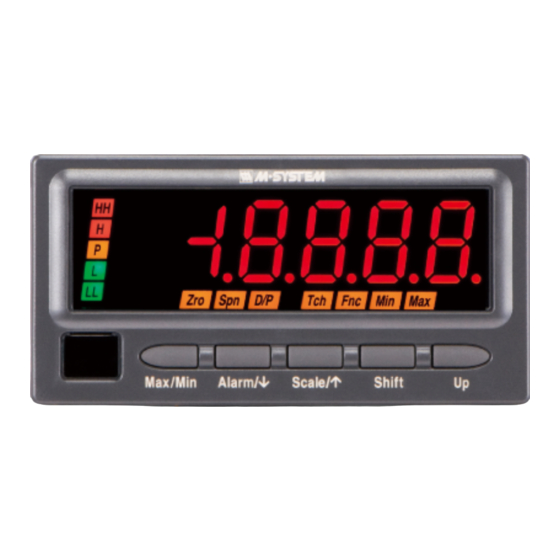
Digital Panel Meters 47 Series
THERMOCOUPLE INPUT DIGITAL PANEL METER
(5 digit, LCD display type)
Model: 47DT
OPERATING MANUAL
5-2-55, Minamitsumori, Nishinari-ku, Osaka 557-0063 JAPAN
Tel: +81-6-6659-8201
Fax: +81-6-6659-8510
http://www.m-system.co.jp/
E-mail: info@m-system.co.jp
47DT OPERATING MANUAL EM-9508-B Rev.7
1
Advertisement
Table of Contents

Related Manuals for M-system 47DT


Summary of Contents for M-system 47DT
- Page 1 Digital Panel Meters 47 Series THERMOCOUPLE INPUT DIGITAL PANEL METER (5 digit, LCD display type) Model: 47DT OPERATING MANUAL 5-2-55, Minamitsumori, Nishinari-ku, Osaka 557-0063 JAPAN Tel: +81-6-6659-8201 Fax: +81-6-6659-8510 http://www.m-system.co.jp/ E-mail: info@m-system.co.jp 47DT OPERATING MANUAL EM-9508-B Rev.7...
-
Page 2: Table Of Contents
2.1.2 BASIC SETTING PROCEDURE ................40 2.2 BASIC SETTING OPERATION AND INSTRUCTIONS ............42 2.2.1 BASIC SETTING OPERATION................42 2.2.2 INSTRUCTIONS ON BASIC OPERATION .............44 3. SETTING INPUT TYPE ................45 3.1 INPUT TYPE LIST ......................45 3.2 OPERATING PROCEDURE ....................46 47DT OPERATING MANUAL EM-9508-B Rev.7... - Page 3 10.7 ONE-SHOT OUTPUT .......................98 10.7.1 OPERATING PROCEDURE ..................98 10.8 ALARM OUTPUT LOGIC (coil energized or de-energized at alarm) ......100 10.8.1 OPERATING PROCEDURE ................100 10.9 MAIN DISPLAY BLINKING AT ALARM ................102 10.9.1 OPERATING PROCEDURE ................102 47DT OPERATING MANUAL EM-9508-B Rev.7...
- Page 4 16. GOING BACK AUTOMATICALLY TO MEASURING MODE ....136 16.1 OPERATING PROCEDURE ................... 137 17. SETTING BURNOUT ................139 17.1 OPERATING PROCEDURE .................... 139 18. SETTING COLD JUNCTION COMPENSATION (CJC) SENSOR ..141 18.1 OPERATING PROCEDURE ................... 141 47DT OPERATING MANUAL EM-9508-B Rev.7...
- Page 5 26.3 PARITY BIT ........................181 26.3.1 OPERATING PROCEDURE ................181 26.4 STOP BIT........................183 26.4.1 OPERATING PROCEDURE ................183 26.5 TIMER ..........................185 26.5.1 OPERATING PROCEDURE ................185 26.6 LONG REGISTER ......................187 26.6.1 OPERATING PROCEDURE ................187 47DT OPERATING MANUAL EM-9508-B Rev.7...
- Page 6 36. INSPECTION / CLEANING ..............216 37. TROUBLESHOOTING ................217 37.1 ERROR MESSAGES ...................... 217 37.2 INITIALIZING SETTING VALUES ................... 218 37.2.1 OPERATING PROCEDURE ................218 37.3 CONFIRMING FIRMWARE VERSION ................219 37.3.1 OPERATING PROCEDURE ................219 47DT OPERATING MANUAL EM-9508-B Rev.7...
- Page 7 38.4.3 ALARM SETTING MODE ...................234 38.4.4 ADVANCED SETTING MODE ................236 38.4.5 MODBUS SETTING MODE ................238 38.4.6 INFRARED COMMUNICATION MODE ..............238 38.4.7 LOCKOUT SETTING MODE ................239 38.4.8 LOOP TEST OUTPUT MODE ................239 38.5 CHARACTER SET ......................240 47DT OPERATING MANUAL EM-9508-B Rev.7...
-
Page 8: Introduction
1. INTRODUCTION 1.1 BEFORE USE..Thank you for choosing M-System. Before use, please check contents of the package you received as outlined below. ■ PACKAGE INCLUDES Digital panel meter Accessories Mounting bracket (2) Terminal cover (1) Watertight packing (1) CJC sensor (1) -
Page 9: Safety Precautions (That Must Be Observed)
• Using the unit continuously may result in a fire or electric shock. Stop using the unit if it is dropped or damaged. • Using the unit continuously may result in a fire or electric shock. 47DT OPERATING MANUAL EM-9508-B Rev.7... - Page 10 Do not use the unit in an atmosphere where combustible gas is present. • Doing so may result in inflammation, ignition, or smoke. Do not cover the ventilation slits with cables, etc. • Doing so may result in malfunction or heating. 47DT OPERATING MANUAL EM-9508-B Rev.7...
-
Page 11: Points Of Caution
• Prepare Infrared Communication Adaptor (model: COP-IRU) separately for the infrared communication. • Transmission distance between the 47DT and the COP-IRU is maximum 1 meter. • Communication can be affected by sunlight, fluorescent lightings employing inverter technology and so forth. Try at a shorter distance if communication is not established. - Page 12 To ensure dustproof and waterproof for front panel follow conditions below. • Observe the designated panel cutout size (W92 × H45 mm) specified by M-System. • The watertight packing included in the product package must be placed between the body and panel when installing on the panel.
-
Page 13: Related Manuals And Products
■ TO USE CONNECTOR FOR BCD OUTPUT AND CONNECTOR TERMINAL BLOCK • Connector Special Cable (model: HDR40) (optional) • Terminal block Connector Terminal Block (model: CNT) (optional) The specification sheet of each product is downloadable at M-System’s web site: http://www.m-system.co.jp/. 47DT OPERATING MANUAL EM-9508-B Rev.7... -
Page 14: Component Identification
• The engineering unit sticker label position is our recommended position. • When an engineering unit is specified by the Ordering Information Sheet, the unit(s) will be shipped with the sticker label put on the above position. 47DT OPERATING MANUAL EM-9508-B Rev.7... - Page 15 ‘L’ indicator turns on when the L (Refer to 6. OPERATION.) alarm is tripped. ‘LL’ indicator turns on when the LL alarm is tripped. ‘P’ indicator turns on when none of the other alarms is tripped. 47DT OPERATING MANUAL EM-9508-B Rev.7...
- Page 16 • The tag No. label sticker position is our recommended position. • When a tag No. is specified, the unit(s) will be shipped with the tag No. sticker label put on the above position. Max. 17 alphanumeric characters can be specified. Please consult M-System’s Hotline. 47DT OPERATING MANUAL EM-9508-B Rev.7...
- Page 17 Alarm Output, RS-485 / Modbus Terminal block (separable) Terminal block (separable) Strap Strap Terminal block (separable) BCD Output, Event Trigger Input, Alarm Output (Photo MOSFET Relay) Terminal block (separable) Strap Euro type connector terminal 50-pin connector 47DT OPERATING MANUAL EM-9508-B Rev.7...
-
Page 18: Installation
• No Options TERMINAL TERMINAL 6.6 (.26) 2–M3 SCREW 4–M3 SCREW 91.5 (3.60) BCD Output, Event Trigger Input, Alarm Output (Photo MOSFET Relay) • 10–M3 SCREW TERMINAL 2–M3 SCREW 12 13 EURO TYPE 50-pin CONNECTOR CONNECTOR TERMINAL 47DT OPERATING MANUAL EM-9508-B Rev.7... -
Page 19: Panel Cutout Dimensions
1.6.2 PANEL CUTOUT DIMENSIONS + 0.8 unit: mm – 0 min. 120 Panel thickness: 1.6 to 8.0 mm 1.6.3 VIEWING ANGLE The display is designed to provide the optimal legibility when viewed from the angles as shown below. 47DT OPERATING MANUAL EM-9508-B Rev.7... -
Page 20: Installation
(2) Remove the mounting brackets. (a) Flip a tab of a bracket. (b) Then pull the bracket toward the terminal block to remove it. Bracket (3) Put the terminal cover through the panel cutout. Panel Terminal cover 47DT OPERATING MANUAL EM-9508-B Rev.7... - Page 21 (6) Push the mounting brackets into the grooves on both sides of the rear module, until they hit the panel’s rear side. Panel Bracket Fixing groove IMPORTANT To conform to degree of protection IP66, confirm visually that the packing is not contorted, cut off or excessively run off the edge after installation. 47DT OPERATING MANUAL EM-9508-B Rev.7...
-
Page 22: Wiring Instructions
• Be sure to confirm the name and polarity of each terminal before wiring to it. • Do not connect anything to unused terminals. • M-System offers a series of lightning surge protectors for protection against induced lightning surges. Please contact M- System to choose appropriate models. - Page 23 AI 1,0-8 RD 0.75 to 1.0 mm AI-TWIN 2X 1,0-8 RD 1.0 to 1.5 mm AI 1,5-8 BK 1.0 to 1.5 mm AI-TWIN 2X 1,5-8 BK Torque: 0.51 N∙m Recommended manufacturer: Phoenix Contact GmbH & Co., KG 47DT OPERATING MANUAL EM-9508-B Rev.7...
-
Page 24: Terminal Assignment
Input signal Excitation DC output Power RS-485/Modbus Alarm output ■ BCD OUTPUT, EVENT TRIGGER INPUT, ALARM OUTPUT (PHOTO MOSFET RELAY) Input signal Excitation DC output Power Event trigger input, BCD output alarm output (photo MOSFET relay) 47DT OPERATING MANUAL EM-9508-B Rev.7... -
Page 25: Wiring Input Signal
A temperature sensor is on the rear Temperature sensor side of the CJC sensor. Screw the CJC sensor to the terminal 2 with the temperature sensor facing downward. Rear side of CJC sensor Wrong installation may destroy the temperature sensor. 47DT OPERATING MANUAL EM-9508-B Rev.7... -
Page 26: Wiring Excitation Supply
Be aware that the excitation supply is not isolated with the input. Excitation supply code: 1, 2 – Excitation supply ■ CONNECTION EXAMPLES +24 V (+12V) – – CJC sensor (model: CJM) Extension Wire Transmitter Ground (resistance 100 ohms or less) – – Other sensor 47DT OPERATING MANUAL EM-9508-B Rev.7... -
Page 27: Wiring Dc Output
• Take measures to reduce noise as much as possible, e.g. by using shielded twisted pair wires for the output signal. Ground the output shield to the most stable earth to prevent noise troubles. DC output – Ground (resistance 100 ohms or less) DC output 47DT OPERATING MANUAL EM-9508-B Rev.7... -
Page 28: Wiring Alarm Output (Relay)
Power Power Varistor Diode Varistor circuit circuit * It is effective to connect a varistor across a load with the supply voltage 24 to 28 V, and across a contact with 100 to 200 V. 47DT OPERATING MANUAL EM-9508-B Rev.7... -
Page 29: Wiring Alarm Output (Photo Mosfet Relay)
Power Power Varistor Diode Varistor circuit circuit * It is effective to connect a varistor across a load with the supply voltage 24 to 28 V, and across a contact with 100 to 120 V. 47DT OPERATING MANUAL EM-9508-B Rev.7... -
Page 30: Wiring Network Interface
RS-485 RS-485 47Dx 47Dx RS-232-C *1 Internal terminating resistor is used when the device is at the end of a transmission line. *2 Install shield cables to all sections and ground them at single point. 47DT OPERATING MANUAL EM-9508-B Rev.7... - Page 31 TX–/RX– Terminator RX– * Connect terminating resistors at both ends of the transmission line. When the 47DT is located at the end, close across the terminals T2 and T3 with a leadwire. ■ SYSTEM CONFIGURATION EXAMPLES • RS-485 / RS-232-C •...
-
Page 32: Wiring Bcd Output
• Be sure to confirm the polarity in wiring. • Make sure that the saturation voltage (residual voltage) of an input device meets the detecting levels of the unit. Other- wise the unit may not operate correctly. • Connect load within the specifications. 47DT OPERATING MANUAL EM-9508-B Rev.7... - Page 33 BCD output data 8×10 Do61 BCD output data 1×10 Do44 BCD output data 4×10 Do11 BCD output data 1×10 Do42 BCD output data 2×10 GND (0 V) Do41 BCD output data 1×10 GND (0 V) 47DT OPERATING MANUAL EM-9508-B Rev.7...
- Page 34 (Fujitsu Component Ltd.) Cover type: HDR-E50LPAS Do41 Cover type: FCN-360C040-B (Honda Tsushin Kogyo Co., Ltd.) Do42 (Fujitsu Component Ltd.) 4th LSD Do44 Do48 Do68 MAX_REQ HDR40-05 HDR40-20 50 cm 2 meters (19.7 in) (6.6 ft) 47DT OPERATING MANUAL EM-9508-B Rev.7...
-
Page 35: Wiring Event Trigger Input
+6 V TIMING Timing HOLD : 13 RESET : 14 S-TMR Startup timer ZERO : 15 2 kΩ HOLD Hold data 1.5 kΩ RESET Reset data open contact ZERO Forced zero collector GND (0 V) 47DT OPERATING MANUAL EM-9508-B Rev.7... -
Page 36: Wiring Power
• Use wires as thick as possible and twist them from the end. • For DC power, confirm the polarity. Power U(+) V(–) AC power DC power ‒ 47DT OPERATING MANUAL EM-9508-B Rev.7... -
Page 37: Installing/Separating Terminal Block
(terminal No. 11 and 16 sides) to remove. IMPORTANT Be sure to turn off the power supply, input signal and power supply to the output relays before installing/separating the terminal block. Euro type connector terminal 47DT OPERATING MANUAL EM-9508-B Rev.7... - Page 38 IMPORTANT Be sure to turn off the power supply, input signal and power supply to the output relays before installing/separating the connector. Terminal cover Insert the connector through the opening. Unlocking buttons 47DT OPERATING MANUAL EM-9508-B Rev.7...
-
Page 39: Attaching/Removing Terminal Cover
(a) Insert the minus tip of a screwdriver into a hole at the lower left corner of the cover. (b) Pull the handle upward. (c) Then insert the screwdriver into a hole at the lower right corner. (d) Pull the handle upward to separate the terminal cover. Terminal cover 47DT OPERATING MANUAL EM-9508-B Rev.7... -
Page 40: Basic Setting And Operation
Parameters used in the basic setting are as shown in the following table. PARAMETER SETTING VALUE SUB DISPLAY SETTING Input type TYPE T TCTYPE T (CC) thermocouple Temperature unit UNIT Temperature indication in °C Decimal point position D-POINT 1 decimal place 47DT OPERATING MANUAL EM-9508-B Rev.7... - Page 41 • Press Shift button to shift the display into the setting standby mode and Up button to select the decimal point posi- tion. Return to Measuring Mode (measurement started). • Hold down Alarm/↓ or Init/↑ button for 1 second or more to apply the new setting and return to Measuring Mode. 47DT OPERATING MANUAL EM-9508-B Rev.7...
-
Page 42: Basic Setting Operation And Instructions
‘9’ will be ‘-’ . Also in setting an alarm setpoint, the indication following ‘9’ will be ‘-’ . • The negative sign (-) must be set to the fifth digit. For example, set ‘-040.0’ instead of ‘-40.0’ . ・・・・・ 47DT OPERATING MANUAL EM-9508-B Rev.7... - Page 43 Press Up button to select your desired setting value. Press Alarm/↓ or Init/↑ button to apply the new setting. • The next or previous parameter setting is indicated. *1 Display depands on the speci cations and settings. 47DT OPERATING MANUAL EM-9508-B Rev.7...
-
Page 44: Instructions On Basic Operation
• Some parameters may not be displayed depending on the lockout settings, I/O option and DC output. • Refer to 7. PARAMETER CONFIGURATION for details. ■ TO TURN OFF POWER • Delay power off for 10 seconds or more after changing of settings. 47DT OPERATING MANUAL EM-9508-B Rev.7... -
Page 45: Setting Input Type
• The bargraph lower and upper limits, analog outputs 0% and 100% are returned to the default values per input type when the input type has been changed. All alarm setpoints of the current bank No. are disabled (reset to ‘-----’ status). It is recommended to record the current settings as necessary. 47DT OPERATING MANUAL EM-9508-B Rev.7... -
Page 46: Operating Procedure
Some alarm indicators turn on with the parameter display. The alarm indication is due to the last status before mode transition held but does not show the unit failure. Press Shift button to shift the display into the setting standby mode. Blinking • The indication ‘TYPEK1’ starts blinking, to which you can apply changes. 47DT OPERATING MANUAL EM-9508-B Rev.7... - Page 47 • Hold down Max/Min button for 1 second or more in the setting standby mode (indication blinking in Step 3 and 4) to return to Measuring Mode without applying the last changes. • If you get lost in a setting mode, you can execute initialization. (Refer to 37.2 INITIALIZING SETTING VALUES.) 47DT OPERATING MANUAL EM-9508-B Rev.7...
-
Page 48: Setting Temperature Unit
• The SD indicates ‘TCTYPE’ . NOTE Some alarm indicators turn on with the parameter display. The alarm indication is due to the last status before mode transition held but does not show the unit failure. 47DT OPERATING MANUAL EM-9508-B Rev.7... - Page 49 ■ TO GO ON TO SET THE SETTING DECIMAL POINT POSITION, Skip to Step 2 in “5. SETTING DECIMAL POINT POSITION” . ■ TO QUIT, Hold down Alarm/↓ or Init/↑ button for 1 second or more to return to Measuring Mode. 47DT OPERATING MANUAL EM-9508-B Rev.7...
- Page 50 • Hold down Max/Min button for 1 second or more in the setting standby mode (indication blinking in Step 4 and 5) to return to Measuring Mode without applying the last changes. • If you get lost in a setting mode, you can execute initialization. (Refer to 37.2 INITIALIZING SETTING VALUES.) 47DT OPERATING MANUAL EM-9508-B Rev.7...
-
Page 51: Setting Decimal Point Position
• The SD indicates ‘TCTYPE’ . NOTE Some alarm indicators turn on with the parameter display. The alarm indication is due to the last status before mode transition held but does not show the unit failure. 47DT OPERATING MANUAL EM-9508-B Rev.7... - Page 52 ■ TO GO ON TO SET THE BARGRAPH TYPE, Skip to Step 2 in “8.1 BARGRAPH TYPE” . ■ TO QUIT, Hold down Alarm/↓ or Init/↑ button for 1 second or more to return to Measuring Mode. 47DT OPERATING MANUAL EM-9508-B Rev.7...
- Page 53 • Hold down Max/Min button for 1 second or more in the setting standby mode (indication blinking in Step 4 and 5) to return to Measuring Mode without applying the last changes. • If you get lost in a setting mode, you can execute initialization. (Refer to 37.2 INITIALIZING SETTING VALUES.) 47DT OPERATING MANUAL EM-9508-B Rev.7...
-
Page 54: Operation
• ‘°C’ or ‘°F’ indicator turns on depending on the temperature unit setting. ■ DISPLAY COLOR • The main display color depends on the settings of the display color and setpoints. Provide 400°C input and make sure that 400.0°C is indicated. 47DT OPERATING MANUAL EM-9508-B Rev.7... -
Page 55: Parameter Configuration
7. PARAMETER CONFIGURATION ■ MODE Parameters can be grouped in several modes. The 47DT has modes as shown in the following table. MODE FUNCTION MEASUREMENT Measuring Normal measurement state where the unit takes in input and provides alarms. Measuring Present value, MAX and MIN values can be indicated, and alarm setpoints can be indicated and set in Measuring Mode. - Page 56 + Init/ + Shift buttons at once for 5 seconds or more. ■ TRANSITION FROM EACH MODE TO MEASURING MODE Hold down Alarm/↓ or Init/↑ button for 1 second or more to return to Measuring Mode. 47DT OPERATING MANUAL EM-9508-B Rev.7...
- Page 57 • The display depends on the specifications and settings. The above displays show default values. • Hold down Alarm/↓ or Init/↑ button for 1 second or more to return to Measuring Mode from each parameter. 47DT OPERATING MANUAL EM-9508-B Rev.7...
- Page 58 HH one-shot output L alarm setpoint HH OFF delay time L trip action HH ON delay time L deadband (hysteresis) HH deadband (hysteresis) L ON delay time Continued on the following page Continued on the following page 47DT OPERATING MANUAL EM-9508-B Rev.7...
- Page 59 • The display depends on the specifications and settings. The above displays show default values. • Hold down Alarm/↓ or Init/↑ button for 1 second or more to return to Measuring Mode from each parameter. 47DT OPERATING MANUAL EM-9508-B Rev.7...
- Page 60 Backlight brightness Display color High-pass lter Automatic return time to Measuring Mode Display reading type Transition time to Lockout Setting Mode Round off low-digit reading Burnout Continued on the following page Continued on the following page 47DT OPERATING MANUAL EM-9508-B Rev.7...
- Page 61 • The display depends on the specifications and settings. The above displays show default values. • Hold down Alarm/↓ or Init/↑ button for 1 second or more to return to Measuring Mode from each parameter. 47DT OPERATING MANUAL EM-9508-B Rev.7...
- Page 62 • Hold down Alarm/↓ or Init/↑ button for 1 second or more to return to Measuring Mode from each parameter. (5) Parameter shifting in Infrared Communication Mode There is no parameter shifting in this mode. 47DT OPERATING MANUAL EM-9508-B Rev.7...
- Page 63 • Hold down Alarm/↓ or Init/↑ button for 1 second or more to return to Measuring Mode from each parameter. (7) Parameter shifting in Loop Test Output Mode There is no parameter shifting in this mode. 47DT OPERATING MANUAL EM-9508-B Rev.7...
-
Page 64: Setting Bargraph
• The number of the LED segments is 20 divided by 10. The bar increases or decreases by 2 segments. • In setting ‘bargraph upper limit < bargraph lower limit’ , the bargraph image is upside down of the above ones. 47DT OPERATING MANUAL EM-9508-B Rev.7... - Page 65 -200.0 to +400.0 Bargraph lower limit: Bargraph upper limit: TYPE L -130.0 to +880.0 -100.0 to +850.0 Bargraph lower limit: Bargraph upper limit: TYPEPR (PR) -30.0 to +1730.0 0.0 to 1700.0 Bargraph lower limit: Bargraph upper limit: 47DT OPERATING MANUAL EM-9508-B Rev.7...
- Page 66 • The bargraph lower and upper limits are returned to the default values per input type when the input type has been changed. • The bargraph lower and upper limits can be set arbitrarily. However it is recommended to use them within the usable range. 47DT OPERATING MANUAL EM-9508-B Rev.7...
-
Page 67: Bargraph Type
SD) or the analog output type (‘ A NG TYP’ on the SD) will be indicated with the bargraph type set to “no bargraph” . • Press Init/↑ button, and the input compensation B compensation value will be indicated (‘CR-B CR’ on the SD). 47DT OPERATING MANUAL EM-9508-B Rev.7... - Page 68 ■ TO GO ON TO SET THE BARGRAPH LOWER LIMIT/UPPER LIMIT, Skip to Step 2 in “8.2 BARGRAPH LOWER LIMIT/UPPER LIMIT” . ■ TO QUIT, Hold down Alarm/↓ or Init/↑ button for 1 second or more to return to Measuring Mode. 47DT OPERATING MANUAL EM-9508-B Rev.7...
-
Page 69: Bargraph Lower Limit/Upper Limit
Press Alarm/↓ button to apply the new value and go to the bargraph upper limit setting. • The bargraph lower limit is registered. • The bargraph upper limit is indicated. • The SD indicates ‘BAR-H’ . 47DT OPERATING MANUAL EM-9508-B Rev.7... - Page 70 (‘ A NG TYP’ on the SD). • Press Init/↑ button, and the bargraph lower limit will be indicated (‘BAR-L’ on the SD). Hold down Alarm/↓ or Init/↑ button for 1 second or more to return to Measuring Mode. 47DT OPERATING MANUAL EM-9508-B Rev.7...
-
Page 71: Setting Analog Output
Display refreshing rate slower than read rate slower than read rate Display value Display value The DC output is provided according to the measured The DC output is proportional to the display value. (temperature) value. 47DT OPERATING MANUAL EM-9508-B Rev.7... - Page 72 -200.0 to +400.0 Analog output 0%: Analog output 100%: TYPE L -130.0 to +880.0 -100.0 to +850.0 Analog output 0%: Analog output 100%: TYPEPR (PR) -30.0 to +1730.0 0.0 to 1700.0 Analog output 0%: Analog output 100%: 47DT OPERATING MANUAL EM-9508-B Rev.7...
- Page 73 • The analog outputs 0% and 100% can be set to any value, however it is recommended to use them within the usable range. 47DT OPERATING MANUAL EM-9508-B Rev.7...
-
Page 74: Analog Output Type
• Press Init/↑ button, and the bargraph upper limit will be indicated (‘BAR-H’ on the SD), or the bargraph type will be indi- cated (‘BAR-GRH’ on the SD) with the bargraph type set to “no bargraph” . 47DT OPERATING MANUAL EM-9508-B Rev.7... - Page 75 ■ TO GO ON TO SET THE ANALOG OUTPUT FUNCTION MODE, Skip to Step 2 in “9.2 ANALOG OUTPUT FUNCTION MODE” . ■ TO QUIT, Hold down Alarm/↓ or Init/↑ button for 1 second or more to return to Measuring Mode. 47DT OPERATING MANUAL EM-9508-B Rev.7...
-
Page 76: Analog Output Function Mode
• Press Alarm/↓ button, and the analog output 0% will be indicated (‘ A NG L’ on the SD). • Press Init/↑ button, and the analog output type will be indicated (‘ A NG TYP’ on the SD).. 47DT OPERATING MANUAL EM-9508-B Rev.7... - Page 77 ■ TO GO ON TO SET THE ANALOG OUTPUTS 0% AND 100%, Skip to Step 2 in “9.3 ANALOG OUTPUT 0% / ANALOG OUTPUT 100%” . ■ TO QUIT, Hold down Alarm/↓ or Init/↑ button for 1 second or more to return to Measuring Mode. 47DT OPERATING MANUAL EM-9508-B Rev.7...
-
Page 78: Analog Output 0% / Analog Output 100
Press Alarm/↓ button to apply the new value and go to the analog output 100% setting. • The analog output 0% is registered. • The analog output 100% is indicated. • The SD indicates ‘ A NG H’ . 47DT OPERATING MANUAL EM-9508-B Rev.7... - Page 79 • Press Init/↑ button, and the analog output 0% will be indicated (‘ A NG L’ on the SD). Hold down Alarm/↓ or Init/↑ button for 1 second or more to return to Measuring Mode. 47DT OPERATING MANUAL EM-9508-B Rev.7...
-
Page 80: Basic Alarm Setting
Blinking in 1.0 second intervals Blinking in 0.5 second intervals Blinking in 0.3 second intervals *1 Selectable only at alarm setting lockout level ‘LV0’ (“completely unlock Alarm Setting Mode”). *2 Configurable for the P status. 47DT OPERATING MANUAL EM-9508-B Rev.7... - Page 81 In the zone setting, alarm trips and resets between each setpoint and the trip action (direction) setting. The P setpoint. Alarm trip action setting is disregarded with status means the zone where the LL, L, H and HH alarm zone alarm. outputs are OFF. 47DT OPERATING MANUAL EM-9508-B Rev.7...
- Page 82 (2) The display value exceeds the setpoint and stays (2) The display value falls below the setpoint and stays over the ON delay time period. Therefore alarm over the OFF delay time period. Therefore alarm output is provided. output is canceled. 47DT OPERATING MANUAL EM-9508-B Rev.7...
- Page 83 • When ‘S.ERR’ and ‘B.ERR’ is indicated, the alarm output depends on the alarm trip at over-range setting. Refer to 12.5 ALARM TRIP ACTION AT OVER-RANGE for details. • All alarm setpoints are disabled (reset to ‘-----’ status) when the input type has been changed. 47DT OPERATING MANUAL EM-9508-B Rev.7...
-
Page 84: Alarm Output Pattern
LL alarm output (lo) LL alarm output (lo) ‘HH’ indicator ‘HH’ indicator ‘H’ indicator ‘H’ indicator ‘P’ indicator ‘P’ indicator ‘L’ indicator ‘L’ indicator ‘LL’ indicator ‘LL’ indicator No output for the zones adjoining the invalid setpoint 47DT OPERATING MANUAL EM-9508-B Rev.7... -
Page 85: Operating Procedure
(‘ A LM BNK’ on the SD) with the bank switching set to “enabled via the front button control” . ■ TO SET THE NEXT PARAMETER, Skip to Step 2 in “10.2 ALARM SETPOINT” . ■ TO QUIT, Hold down Alarm/↓ or Init/↑ button for 1 second or more to return to Measuring Mode. 47DT OPERATING MANUAL EM-9508-B Rev.7... -
Page 86: Alarm Setpoint
0.0 to 2300.0 TYPE N -230.0 to +1330.0 -200.0 to +1300.0 TYPE U -230.0 to +430.0 -200.0 to +400.0 TYPE L -130.0 to +880.0 -100.0 to +850.0 TYPEPR (PR) -30.0 to +1730.0 0.0 to 1700.0 47DT OPERATING MANUAL EM-9508-B Rev.7... - Page 87 • The default values of the LL and HH setpoints are ‘-----’ for dual alarm output option (SPDT relay, 2 points). • The default values of all setpoints are ‘-----’ for no alarm output option. 47DT OPERATING MANUAL EM-9508-B Rev.7...
-
Page 88: Operating Procedure
• The fifth digit starts blinking, to which you can apply changes. • Set within the range of -999.9 to 9999.9. IMPORTANT Specify ‘-----’ to disable the alarm output. NOTE Set to 1 decimal place regardless of the decimal point position setting. 47DT OPERATING MANUAL EM-9508-B Rev.7... - Page 89 ■ TO SET THE NEXT PARAMETER, Skip to Step 2 in “10.3 TRIP ACTION (LO/HI)” . ■ TO QUIT, Hold down Alarm/↓ or Init/↑ button for 1 second or more to return to Measuring Mode. 47DT OPERATING MANUAL EM-9508-B Rev.7...
-
Page 90: Trip Action (Lo/Hi)
• The SD indicates ‘LIMT LL’ (‘LIMT L’ , ‘LIMT H’ or ‘LIMT HH’). • ‘LL’ (‘L’ , ‘H’ or ‘HH’) indicator starts blinking. Press Shift and Up buttons to select the LL (L, H or HH) trip action. Blinking • Select ‘LOW’ or ‘HIGH’ . 47DT OPERATING MANUAL EM-9508-B Rev.7... - Page 91 Repeat operation from Step 2. ■ TO SET THE NEXT PARAMETER, Skip to Step 2 in “10.4 DEADBAND” . ■ TO QUIT, Hold down Alarm/↓ or Init/↑ button for 1 second or more to return to Measuring Mode. 47DT OPERATING MANUAL EM-9508-B Rev.7...
-
Page 92: Deadband
HH) deadband. • The third digit starts blinking, to which you can apply changes. • Set within the range of 00.0 to 99.9. NOTE Set to 1 decimal place regardless of the decimal point position setting. 47DT OPERATING MANUAL EM-9508-B Rev.7... - Page 93 ■ TO SET THE NEXT PARAMETER, Skip to Step 2 in “10.5 ON DELAY TIME” . ■ TO QUIT, Hold down Alarm/↓ or Init/↑ button for 1 second or more to return to Measuring Mode. 47DT OPERATING MANUAL EM-9508-B Rev.7...
-
Page 94: On Delay Time
• The third digit starts blinking, to which you can apply changes. • Set within the range of 000 to 999. NOTE The decimal point is not indicated. Set as ‘setting value × 100 milliseconds’ . 47DT OPERATING MANUAL EM-9508-B Rev.7... - Page 95 ■ TO SET THE NEXT PARAMETER, Skip to Step 2 in “10.6 OFF DELAY TIME” . ■ TO QUIT, Hold down Alarm/↓ or Init/↑ button for 1 second or more to return to Measuring Mode. 47DT OPERATING MANUAL EM-9508-B Rev.7...
-
Page 96: Off Delay Time
• The LL (L, H, HH or P) OFF delay time is indicated. • The SD indicates ‘OFDLYLL’ (‘OFDLY L’ , ‘OFDLY H’ , ‘OFDLYHH’ or ‘OFDLY P’). • ‘LL’ (‘L’ , ‘H’ , ‘HH’ or ‘P’) indicator starts blinking. 47DT OPERATING MANUAL EM-9508-B Rev.7... - Page 97 Repeat operation from Step 2. ■ TO SET THE NEXT PARAMETER, Skip to Step 2 in “10.7 ONE-SHOT OUTPUT” . ■ TO QUIT, Hold down Alarm/↓ or Init/↑ button for 1 second or more to return to Measuring Mode. 47DT OPERATING MANUAL EM-9508-B Rev.7...
-
Page 98: One-Shot Output
• The LL (L, H, HH or P) one-shot output is indicated. • The SD indicates ‘SHOT LL’ (‘SHOT L’ , ‘SHOT H’ , ‘SHOT HH’ or ‘SHOT P’). • ‘LL’ (‘L’ , ‘H’ , ‘HH’ or ‘P’) indicator starts blinking. 47DT OPERATING MANUAL EM-9508-B Rev.7... - Page 99 Skip to Step 2 in “10.8 ALARM OUTPUT LOGIC (coil energized or de-energized at alarm)” . ■ TO QUIT, Hold down Alarm/↓ or Init/↑ button for 1 second or more to return to Measuring Mode. 47DT OPERATING MANUAL EM-9508-B Rev.7...
-
Page 100: Alarm Output Logic (Coil Energized Or De-Energized At Alarm)
• ‘LL’ (‘L’ , ‘H’ , ‘HH’ or ‘P’) indicator starts blinking. Press Shift and Up buttons to select the LL (L, H, HH or P) coil at alarm. Blinking • Select ‘EN’ or ‘DE’ . 47DT OPERATING MANUAL EM-9508-B Rev.7... - Page 101 ■ TO SET THE NEXT PARAMETER, Skip to Step 2 in “10.9 MAIN DISPLAY BLINKING AT ALARM” . ■ TO QUIT, Hold down Alarm/↓ or Init/↑ button for 1 second or more to return to Measuring Mode. 47DT OPERATING MANUAL EM-9508-B Rev.7...
-
Page 102: Main Display Blinking At Alarm
With the bank switching set to “enabled via the front button control” , the bank No. is indicated (‘ A LM BNK’ on the SD). Press Alarm/↓ or Init/↑ button to go to the main display blink- ing at alarm setting. • The main display blinking at alarm is indicated. • The SD indicates ‘ A LMBLNK’ . 47DT OPERATING MANUAL EM-9508-B Rev.7... - Page 103 • Press Init/↑ button, and the HH setpoint will be indicated (‘ A LARMHH’ on the SD), or the P coil at alarm will be indicated (‘RELAY P’ on the SD) with the alarm setting lockout set to “completely unlock Alarm Setting Mode” . Hold down Alarm/↓ or Init/↑ button for 1 second or more to return to Measuring Mode. 47DT OPERATING MANUAL EM-9508-B Rev.7...
-
Page 104: Bank Setting
11. BANK SETTING The 47DT has 8 areas (banks) to save a set of preset alarm setpoints. Switching them enables the setpoints to be changed easily. This bank switching can be “enabled via the front button control” or “enabled via Modbus communication”... -
Page 105: Bank Switching
Press Alarm/↓ or Init/↑ button to go to the bank switching set- ting. • The bank switching is indicated. • The SD indicates ‘BNK-CHG’ . Press Shift and Up buttons to select the bank switching. Blinking • Select one among ‘OFF’ , ‘KEY’ and ‘COM’ . 47DT OPERATING MANUAL EM-9508-B Rev.7... - Page 106 (‘BCD-REQ’ on the SD) with the I/O option code ‘5’ , ‘9’ or ‘ A ’ . • Press Init/↑ button, and the LCD contrast will be indicated (‘CNTRAST’ on the SD). Hold down Alarm/↓ or Init/↑ button for 1 second or more to return to Measuring Mode. 47DT OPERATING MANUAL EM-9508-B Rev.7...
-
Page 107: Bank Copy
• Press Alarm/↓ button, and the bank No. will be indicated (‘ A LM BNK’ on the SD). • Press Init/↑ button, and the main display blinking at alarm will be indicated (‘ A LMBLNK’ on the SD). 47DT OPERATING MANUAL EM-9508-B Rev.7... - Page 108 ■ TO GO ON TO SET THE BANK NO., Skip to Step 2 in “11.3 BANK NO.” . ■ TO QUIT, Hold down Alarm/↓ or Init/↑ button for 1 second or more to return to Measuring Mode. 47DT OPERATING MANUAL EM-9508-B Rev.7...
-
Page 109: Bank No
■ TO GO ON TO SET THE ALARM SETPOINT, Skip to Step 2 in “10.2 ALARM SETPOINT” . ■ TO QUIT, Hold down Alarm/↓ or Init/↑ button for 1 second or more to return to Measuring Mode. 47DT OPERATING MANUAL EM-9508-B Rev.7... -
Page 110: Advanced Alarm Setting
0.0 – 999.9 seconds Standby sequence Output immediately at the startup Output standing by until the input enters P zone Alarm trip at over-range Alarm trip action valid at over-range No alarm trip action at over-range 47DT OPERATING MANUAL EM-9508-B Rev.7... - Page 111 L setpoint. The output is held (4) The L alarm output is not provided when the input even when it exceeds the L setpoint. The display falls below the L setpoint. value corresponds to the measured value. 47DT OPERATING MANUAL EM-9508-B Rev.7...
- Page 112 (2) After the alarm power ON delay time is elapsed, the (2) After the display value enters the P zone, the alarm alarm output is provided when the display value falls output is provided when it falls below the L setpoint. below the L setpoint. 47DT OPERATING MANUAL EM-9508-B Rev.7...
-
Page 113: P Output
With the I/O option code ‘6’ or ‘ A ’ , the event trigger mode is indicated (‘EVENT’ on the SD). Press Alarm/↓ or Init/↑ button to go to the P output setting. • The P output is indicated. • The SD indicates ‘PASS’ . 47DT OPERATING MANUAL EM-9508-B Rev.7... - Page 114 • Press Alarm/↓ button, and the latching alarm will be indicated (‘OUT-STP’ on the SD). • Press Init/↑ button, and the manual sub display reset will be indicated (‘S-DISP’ on the SD). Hold down Alarm/↓ or Init/↑ button for 1 second or more to return to Measuring Mode. 47DT OPERATING MANUAL EM-9508-B Rev.7...
-
Page 115: Latching Alarm
• The latching alarm is indicated. • The SD indicates ‘OUT-STP’ . Press Shift and Up buttons to select the latching alarm. Blinking • Select one among ‘OFF’ , ‘OUT’ and ‘ A LL’ . 47DT OPERATING MANUAL EM-9508-B Rev.7... - Page 116 • Press Alarm/↓ button, and the alarm power ON delay will be indicated (‘PWR-DLY’ on the SD). • Press Init/↑ button, and the P output will be indicated (‘PASS’ on the SD). Hold down Alarm/↓ or Init/↑ button for 1 second or more to return to Measuring Mode. 47DT OPERATING MANUAL EM-9508-B Rev.7...
-
Page 117: Alarm Power On Delay
Then press Shift and Up buttons to set the alarm power Blinking ON delay. • The forth digit starts blinking, to which you can apply changes. • Set within the range of 000.0 to 999.9. 47DT OPERATING MANUAL EM-9508-B Rev.7... - Page 118 • Press Alarm/↓ button, and the standby sequence will be indicated (‘STDBY’ on the SD). • Press Init/↑ button, and the latching alarm will be indicated (‘OUT-STP’ on the SD). Hold down Alarm/↓ or Init/↑ button for 1 second or more to return to Measuring Mode. 47DT OPERATING MANUAL EM-9508-B Rev.7...
-
Page 119: Standby Sequence
Press Alarm/↓ or Init/↑ button to go to the standby sequence setting. • The standby sequence is indicated. • The SD indicates ‘STDBY’ . Press Shift and Up buttons to select the standby sequence. Blinking • Select ‘OFF’ or ‘ON’ . 47DT OPERATING MANUAL EM-9508-B Rev.7... - Page 120 • Press Alarm/↓ button, and the alarm trip at over-range will be indicated (‘SE-ALM’ on the SD). • Press Init/↑ button, and the alarm power ON delay will be indicated (‘PWR-DLY’ on the SD). Hold down Alarm/↓ or Init/↑ button for 1 second or more to return to Measuring Mode. 47DT OPERATING MANUAL EM-9508-B Rev.7...
-
Page 121: Alarm Trip Action At Over-Range
• The alarm trip at over-range is indicated. • The SD indicates ‘SE-ALM’ . Press Shift and Up buttons to select the alarm trip at over- range. Blinking • Select ‘ON’ or ‘OFF’ . 47DT OPERATING MANUAL EM-9508-B Rev.7... - Page 122 • Press Alarm/↓ button, and the round off low-digit reading will be indicated (‘STEP’ on the SD). • Press Init/↑ button, and the standby sequence will be indicated (‘STDBY’ on the SD). Hold down Alarm/↓ or Init/↑ button for 1 second or more to return to Measuring Mode. 47DT OPERATING MANUAL EM-9508-B Rev.7...
-
Page 123: Averaging Input
× averaging time’ , depending on the display sample is added to be averaged with the oldest one refreshing rate. omitted. (3) Such operation is repeated. The display is updated every sampling period (50 milliseconds, depending on the display refreshing rate). 47DT OPERATING MANUAL EM-9508-B Rev.7... - Page 124 64 samples (3.2 second intervals) 128 samples (6.4 second intervals) 256 samples (12.8 second intervals) 512 samples (32.6 second intervals) NOTE The averaging time setting affects the DC output. Refer to 9. SETTING ANALOG OUTPUT for details. 47DT OPERATING MANUAL EM-9508-B Rev.7...
-
Page 125: Averaging Type
• Press Init/↑ button, and the firmware version indication will be indicated (‘FRM-VER’ on the SD), or the startup timer will be indicated (‘STR-TMR’ on the SD) with the I/O option code ‘6’ or ‘ A ’ . 47DT OPERATING MANUAL EM-9508-B Rev.7... - Page 126 ■ TO GO ON TO SET THE AVERAGING TIME, Skip to Step 2 in “13.2 AVERAGING TIME” . ■ TO QUIT, Hold down Alarm/↓ or Init/↑ button for 1 second or more to return to Measuring Mode. 47DT OPERATING MANUAL EM-9508-B Rev.7...
-
Page 127: Averaging Time
Press Shift and Up buttons to select the averaging time. Blinking • Select one among ‘OFF’ , ‘2’ , ‘4’ , ‘8’ , ‘16’ , ‘32’ , ‘64’ , ‘128’ , ‘256’ and ‘512’ . 47DT OPERATING MANUAL EM-9508-B Rev.7... - Page 128 • Press Alarm/↓ button, and the low-end cutout will be indicated (‘ZEROLMT’ on the SD). • Press Init/↑ button, and the averaging type will be indicated (‘ A VE-TP’ on the SD). Hold down Alarm/↓ or Init/↑ button for 1 second or more to return to Measuring Mode. 47DT OPERATING MANUAL EM-9508-B Rev.7...
-
Page 129: Eliminating Fluctuation Around "0
-4.9 to +4.9 will be cut to 0. • The low-end cutout setting affects the DC output when the analog output function mode is set to “proportional to the display value” . Refer to 9. SETTING ANALOG OUTPUT for details. 47DT OPERATING MANUAL EM-9508-B Rev.7... -
Page 130: Low-End Cutout
• The low-end cutout is indicated. • The SD indicates ‘ZEROLMT’ . Press Shift and Up buttons to select the low-end cutout. Blinking • Select one among ‘OFF’ , ‘ON’ and ‘ A BS’ . 47DT OPERATING MANUAL EM-9508-B Rev.7... - Page 131 ■ TO GO ON TO SET THE LOW-END CUTOUT VALUE, Skip to Step 2 in “14.2 LOW-END CUTOUT VALUE” . ■ TO QUIT, Hold down Alarm/↓ or Init/↑ button for 1 second or more to return to Measuring Mode. 47DT OPERATING MANUAL EM-9508-B Rev.7...
-
Page 132: Low-End Cutout Value
• The second digit starts blinking, to which you can apply changes. • Set within the range of 0.0 to 9.9. NOTE Set to 1 decimal place regardless of the decimal point position setting. 47DT OPERATING MANUAL EM-9508-B Rev.7... - Page 133 • Press Alarm/↓ button, and the display color will be indicated (‘COLOR’ on the SD). • Press Init/↑ button, and the low-end cutout will be indicated (‘ZEROLMT’ on the SD). Hold down Alarm/↓ or Init/↑ button for 1 second or more to return to Measuring Mode. 47DT OPERATING MANUAL EM-9508-B Rev.7...
-
Page 134: Setting Display Color
With the I/O option code ‘6’ or ‘ A ’ , the event trigger mode is indicated (‘EVENT’ on the SD). Press Alarm/↓ or Init/↑ button to go to the display color setting. • The display color is indicated. • The SD indicates ‘COLOR’ . 47DT OPERATING MANUAL EM-9508-B Rev.7... - Page 135 • Press Init/↑ button, and the low-end cutout value will be indicated (‘ZLMTN’ on the SD), or the low-end cutout will be indicated (‘ZEROLMT’ on the SD) with the low-end cutout set to “low-end cutout OFF” . Hold down Alarm/↓ or Init/↑ button for 1 second or more to return to Measuring Mode. 47DT OPERATING MANUAL EM-9508-B Rev.7...
-
Page 136: Going Back Automatically To Measuring Mode
Alarm Setting Mode Enabled Advanced Setting Mode Enabled Modbus Setting Mode Enabled Infrared Communication Mode Disabled Lockout Setting Mode Enabled Loop Test Output Mode Disabled *1 Refer to 28.2 MANUAL SUB DISPLAY RESET for details. 47DT OPERATING MANUAL EM-9508-B Rev.7... -
Page 137: Operating Procedure
Then press Shift and Up buttons to set the automatic Blinking return time to Measuring Mode. • The second digit starts blinking, to which you can apply changes. • Set within the range of 00 to 99. 47DT OPERATING MANUAL EM-9508-B Rev.7... - Page 138 • Press Alarm/↓ button, and the transition time to Lockout Setting Mode will be indicated (‘PROTECT’ on the SD). • Press Init/↑ button, and the display color will be indicated (‘COLOR’ on the SD). Hold down Alarm/↓ or Init/↑ button for 1 second or more to return to Measuring Mode. 47DT OPERATING MANUAL EM-9508-B Rev.7...
-
Page 139: Setting Burnout
With the I/O option code ‘6’ or ‘ A ’ , the event trigger mode is indicated (‘EVENT’ on the SD). Press Alarm/↓ or Init/↑ button to go to the burnout setting. • The burnout is indicated. • The SD indicates ‘BURNOUT’ . 47DT OPERATING MANUAL EM-9508-B Rev.7... - Page 140 • Press Init/↑ button, and the transition time to Lockout Setting Mode will be indicated (‘PROTECT’ on the SD). Hold down Alarm/↓ or Init/↑ button for 1 second or more to return to Measuring Mode. 47DT OPERATING MANUAL EM-9508-B Rev.7...
-
Page 141: Setting Cold Junction Compensation (Cjc) Sensor
To use the CJC sensor of the 47DT, enable the CJC sensor ‘ON’ . When an external reference junction compensator is used, disable it ‘OFF’ . The default is ‘ON’ . - Page 142 • Press Alarm/↓ button, and the display refreshing rate will be indicated (‘D-REFSH’ on the SD). • Press Init/↑ button, and the burnout will be indicated (‘BURNOUT’ on the SD). Hold down Alarm/↓ or Init/↑ button for 1 second or more to return to Measuring Mode. 47DT OPERATING MANUAL EM-9508-B Rev.7...
-
Page 143: Adjusting Display Refreshing Rate
19. ADJUSTING DISPLAY REFRESHING RATE The 47DT measures input signal at the read rate 50 milliseconds. The display refreshing rate can be slower than this rate (figure below) within the range of 0.1 to 99.9 seconds. With this value set to 00.0, the refreshing rate will be the same as the read rate (50 milliseconds) (table below). -
Page 144: Operating Procedure
Then press Shift and Up buttons to set the display Blinking refreshing rate. • The third digit starts blinking, to which you can apply changes. • Set within the range of 00.0 to 99.9. 47DT OPERATING MANUAL EM-9508-B Rev.7... - Page 145 (‘S-DISP’ on the SD) with the alarm setting lockout set to “completely unlock Alarm Set- ting Mode” . • Press Init/↑ button, and the CJC sensor will be indicated (‘CJM’ on the SD). Hold down Alarm/↓ or Init/↑ button for 1 second or more to return to Measuring Mode. 47DT OPERATING MANUAL EM-9508-B Rev.7...
-
Page 146: Rounding Off Lowest Digit Reading
LOW-DIGIT INDICATION OF MEASURED VALUE NOTE The round off low-digit reading setting affects the DC output when the analog output function mode is set to “proportional to the display value” . Refer to 9. SETTING ANALOG OUTPUT for details. 47DT OPERATING MANUAL EM-9508-B Rev.7... -
Page 147: Operating Procedure
• The round off low-digit reading is indicated. • The SD indicates ‘STEP’ . Press Shift and Up buttons to select the round off low-digit reading. Blinking • Select one among ‘OFF’ , ‘2’ , ‘5’ and ‘10’ . 47DT OPERATING MANUAL EM-9508-B Rev.7... - Page 148 • Press Alarm/↓ button, and the display reading type will be indicated (‘M-DISP’ on the SD). • Press Init/↑ button, and the alarm trip at over-range will be indicated (‘SE-ALM’ on the SD). Hold down Alarm/↓ or Init/↑ button for 1 second or more to return to Measuring Mode. 47DT OPERATING MANUAL EM-9508-B Rev.7...
-
Page 149: Detecting Steep Input Changes
(5.0 + 4.0) = 4.5 9.5 – 4.5 = 5.0 (4.5 + 9.5) = 7.0 *2 Analog output may not simply increase/decrease depending upon timing of the input supplied in relation to the sampling rate. 47DT OPERATING MANUAL EM-9508-B Rev.7... - Page 150 (and bargraph lower and upper limits, analog outputs 0% and 100% as necessary), taking account of this. • The high-pass filter setting affects the DC output when the analog output function mode is set to “proportional to the display value” . Refer to 9. SETTING ANALOG OUTPUT for details. 47DT OPERATING MANUAL EM-9508-B Rev.7...
-
Page 151: Operating Procedure
Press Alarm/↓ or Init/↑ button to go to the high-pass filter set- ting. • The high-pass filter is indicated. • The SD indicates ‘HP-F’ . Press Shift and Up buttons to select the high-pass filter. Blinking • Select ‘OFF’ or ‘ON’ . 47DT OPERATING MANUAL EM-9508-B Rev.7... - Page 152 • Press Alarm/↓ button, and the backlight brightness will be indicated (‘BRIGHT’ on the SD). • Press Init/↑ button, and the display reading type will be indicated (‘M-DISP’ on the SD). Hold down Alarm/↓ or Init/↑ button for 1 second or more to return to Measuring Mode. 47DT OPERATING MANUAL EM-9508-B Rev.7...
-
Page 153: Adjusting Brightness Of Display
The brightness can be selected in the following table. ■ BACKLIGHT BRIGHTNESS MAIN DISPLAY FUNCTION DEFAULT VALUE Brightness level 1 (dark) Brightness level 2 Brightness level 3 (bright) ■ ADJUSTMENT IMAGE Increasing brightness Decreasing brightness Increasing brightness Decreasing brightness 47DT OPERATING MANUAL EM-9508-B Rev.7... -
Page 154: Operating Procedure
Press Alarm/↓ or Init/↑ button to go to the backlight brightness setting. • The backlight brightness is indicated. • The SD indicates ‘BRIGHT’ . Press Shift and Up buttons to select the backlight brightness. Blinking • Select one among ‘1’ , ‘2’ and ‘3’ . 47DT OPERATING MANUAL EM-9508-B Rev.7... - Page 155 • Press Alarm/↓ button, and the LCD contrast will be indicated (‘CNTRAST’ on the SD). • Press Init/↑ button, and the high-pass filter will be indicated (‘HP-F’ on the SD). Hold down Alarm/↓ or Init/↑ button for 1 second or more to return to Measuring Mode. 47DT OPERATING MANUAL EM-9508-B Rev.7...
-
Page 156: Adjusting Lcd Contrast
Contrast level 3 Contrast level 4 Contrast level 5 (middle) Contrast level 6 Contrast level 7 Contrast level 8 Contrast level 9 Contrast level 10 (high) ■ ADJUSTMENT IMAGE Higher contrast Lower contrast Higher contrast Lower contrast 47DT OPERATING MANUAL EM-9508-B Rev.7... -
Page 157: Operating Procedure
Press Shift and Up buttons to select the LCD contrast. Blinking • Select one among ‘1’ , ‘2’ , ‘3’ , ‘4’ , ‘5’ , ‘6’ , ‘7’ , ‘8’ , ‘9’ and ‘10’ . 47DT OPERATING MANUAL EM-9508-B Rev.7... - Page 158 • Press Alarm/↓ button, and the bank switching will be indicated (‘BNK-CHG’ on the SD). • Press Init/↑ button, and the backlight brightness will be indicated (‘BRIGHT’ on the SD). Hold down Alarm/↓ or Init/↑ button for 1 second or more to return to Measuring Mode. 47DT OPERATING MANUAL EM-9508-B Rev.7...
-
Page 159: Setting Event Trigger Input
“B.ERR,” however, the alarm and analog outputs are reset (do not change). ZERO ---- Not to be used NOTE The negative logic (ON at low signal) is as shown in the figure on the right. Negative logic OFF (Hi) OFF (Hi) ON (Lo) 47DT OPERATING MANUAL EM-9508-B Rev.7... - Page 160 OFF, the stored MIN value is indicated (Table 9). Peak-to-peak hold Measures and stores MAX and MIN values while the TIMING signal is ON. When the signal is OFF, the stored ‘MAX value - MIN value’ is indicated (Table 10). 47DT OPERATING MANUAL EM-9508-B Rev.7...
- Page 161 TIMING within RESET: Invalid *1 Scaling error DC output Proportional to the display reading. For no measured Not measured if a scaling error occurs *2 Measuring while TIMING is ON data, the value is 0%. 47DT OPERATING MANUAL EM-9508-B Rev.7...
- Page 162 • The MAX and MIN values while the TIMING signal is ON are indicated with the front button control in the modes except the normal and sampling hold modes. • The scaling error in Tables 6 to 10 includes ‘B.ERR’ . 47DT OPERATING MANUAL EM-9508-B Rev.7...
- Page 163 Available TIMING Counting Counting S-TMR 2 sec. Halt 3 sec. NOTE The startup timer can be set in the normal mode, however when the S-TMR is ON, the measurement is stopped during the timer period. 47DT OPERATING MANUAL EM-9508-B Rev.7...
-
Page 164: Event Trigger Mode
• Press Alarm/↓ button, and the ON timing delay will be indicated (‘ON-TDLY’ on the SD), or the startup timer will be indi- cated (‘STR-TMR’ on the SD) with the event trigger mode set to “normal” . • Press Init/↑ button, and the firmware version indication will be indicated (‘FRM-VER’ on the SD). 47DT OPERATING MANUAL EM-9508-B Rev.7... - Page 165 ■ TO GO ON TO SET THE ON TIMING DELAY, Skip to Step 2 in “24.2 ON TIMING DELAY” . ■ TO QUIT, Hold down Alarm/↓ or Init/↑ button for 1 second or more to return to Measuring Mode. 47DT OPERATING MANUAL EM-9508-B Rev.7...
-
Page 166: On Timing Delay
Then press Shift and Up buttons to set the ON timing Blinking delay. • The forth digit starts blinking, to which you can apply changes. • Set within the range of 000.0 to 999.9. 47DT OPERATING MANUAL EM-9508-B Rev.7... - Page 167 ■ TO GO ON TO SET THE OFF TIMING DELAY, Skip to Step 2 in “24.3 OFF TIMING DELAY” . ■ TO QUIT, Hold down Alarm/↓ or Init/↑ button for 1 second or more to return to Measuring Mode. 47DT OPERATING MANUAL EM-9508-B Rev.7...
-
Page 168: Off Timing Delay
Then press Shift and Up buttons to set the OFF timing Blinking delay. • The forth digit starts blinking, to which you can apply changes. • Set within the range of 000.0 to 999.9. 47DT OPERATING MANUAL EM-9508-B Rev.7... - Page 169 ■ TO GO ON TO SET THE STARTUP TIMER, Skip to Step 2 in “24.4 STARTUP TIMER” . ■ TO QUIT, Hold down Alarm/↓ or Init/↑ button for 1 second or more to return to Measuring Mode. 47DT OPERATING MANUAL EM-9508-B Rev.7...
-
Page 170: Startup Timer
Press Shift button to shift the display into the setting standby mode. Then press Shift and Up buttons to set the startup Blinking timer. • The third digit starts blinking, to which you can apply changes. • Set within the range of 00.0 to 99.9. 47DT OPERATING MANUAL EM-9508-B Rev.7... - Page 171 (‘EVENT’ on the SD) with the event trigger mode set to “normal” , or the ON timing delay will be indicated (‘ON-TDLY’ on the SD) with the event trigger mode set to “sampling hold” . Hold down Alarm/↓ or Init/↑ button for 1 second or more to return to Measuring Mode. 47DT OPERATING MANUAL EM-9508-B Rev.7...
-
Page 172: Setting Bcd Output
HH alarm trip output Follows HH alarm output. H alarm trip output Follows H alarm output. P status output Follows P status. L alarm trip output Follows L alarm output. LL alarm trip output Follows LL alarm output. 47DT OPERATING MANUAL EM-9508-B Rev.7... - Page 173 • The HOLD and RESET signal logics are negative, not configurable. (default) • ON/OFF of the positive and negative logics is as shown in the right table. Positive logic ON (Hi) OFF (Lo) OFF (Lo) 47DT OPERATING MANUAL EM-9508-B Rev.7...
-
Page 174: Bcd Logic
Press Alarm/↓ or Init/↑ button to go to the DATA output logic setting. • The DATA output logic is indicated. • The SD indicates ‘BCD-DAT’ . Press Shift and Up buttons to select the DATA output logic. Blinking • Select ‘ON’ or ‘OFF’ . 47DT OPERATING MANUAL EM-9508-B Rev.7... - Page 175 • Press Alarm/↓ button, and the status output logic will be indicated (‘BCD-STA’ on the SD). • Press Init/↑ button, and the DAV output logic will be indicated (‘BCD-DAV’ on the SD). Hold down Alarm/↓ or Init/↑ button for 1 second or more to return to Measuring Mode. 47DT OPERATING MANUAL EM-9508-B Rev.7...
-
Page 176: Setting Modbus Communication
26. SETTING MODBUS COMMUNICATION Data readout and parameter configuration of the 47DT with a PLC or a PC are available via Modbus communication. This manual describes setting procedures of the device address, baud rate, parity bit, stop bit, long register and timers. Refer to Modbus Protocol Reference Guide for 47Dx for the protocols and commands. -
Page 177: Device Address
• And the next parameter setting is indicated. NOTE • Press Alarm/↓ button, and the baud rate will be indicated (‘B-RATE’ on the SD). • Press Init/↑ button, and the long register will be indicated (‘L-WORD’ on the SD). 47DT OPERATING MANUAL EM-9508-B Rev.7... - Page 178 ■ TO QUIT, Hold down Alarm/↓ or Init/↑ button for 1 second or more to return to Measuring Mode. IMPORTANT Modbus setting changes are enabled only after the power supply has been turned off and on. 47DT OPERATING MANUAL EM-9508-B Rev.7...
-
Page 179: Baud Rate
• And the next parameter setting is indicated. NOTE • Press Alarm/↓ button, and the parity bit will be indicated (‘PARITY’ on the SD). • Press Init/↑ button, and the device address will be indicated (‘EQP-NO’ on the SD). 47DT OPERATING MANUAL EM-9508-B Rev.7... - Page 180 ■ TO QUIT, Hold down Alarm/↓ or Init/↑ button for 1 second or more to return to Measuring Mode. IMPORTANT Modbus setting changes are enabled only after the power supply has been turned off and on. 47DT OPERATING MANUAL EM-9508-B Rev.7...
-
Page 181: Parity Bit
• And the next parameter setting is indicated. NOTE • Press Alarm/↓ button, and the stop bit will be indicated (‘STOPBIT’ on the SD). • Press Init/↑ button, and the baud rate will be indicated (‘B-RATE’ on the SD). 47DT OPERATING MANUAL EM-9508-B Rev.7... - Page 182 ■ TO QUIT, Hold down Alarm/↓ or Init/↑ button for 1 second or more to return to Measuring Mode. IMPORTANT Modbus setting changes are enabled only after the power supply has been turned off and on. 47DT OPERATING MANUAL EM-9508-B Rev.7...
-
Page 183: Stop Bit
• And the next parameter setting is indicated. NOTE • Press Alarm/↓ button, and the T1.5 timer will be indicated (‘T15’ on the SD). • Press Init/↑ button, and the parity bit will be indicated (‘PARITY’ on the SD). 47DT OPERATING MANUAL EM-9508-B Rev.7... - Page 184 Hold down Alarm/↓ or Init/↑ button for 1 second or more to return to Measuring Mode. IMPORTANT Modbus setting changes are enabled only after the power supply has been turned off and on. 47DT OPERATING MANUAL EM-9508-B Rev.7...
-
Page 185: Timer
• The second digit starts blinking, to which you can apply changes. • Set within the range of 01 to 60. NOTE The decimal point is not indicated. Set as ‘setting value × 0.1’ . 47DT OPERATING MANUAL EM-9508-B Rev.7... - Page 186 • Modbus setting changes are enabled only after the power supply has been turned off and on. • The T1.5 and T3.5 timers are specified as 1.5 and 3.5 characters times in Modbus standard specifications. These pa- rameters are not necessary to be changed normally. 47DT OPERATING MANUAL EM-9508-B Rev.7...
-
Page 187: Long Register
• And the next parameter setting is indicated. NOTE • Press Alarm/↓ button, and the device address will be indicated (‘EQP-NO’ on the SD). • Press Init/↑ button, and the T3.5 timer will be indicated (‘T35’ on the SD). 47DT OPERATING MANUAL EM-9508-B Rev.7... - Page 188 Hold down Alarm/↓ or Init/↑ button for 1 second or more to return to Measuring Mode. IMPORTANT Modbus setting changes are enabled only after the power supply has been turned off and on. 47DT OPERATING MANUAL EM-9508-B Rev.7...
-
Page 189: Loop Testing
27. LOOP TESTING The 47DT can provide simulated analog output with the display value manually adjusted. It is called loop test output. It is convenient to check or calibrate a receiving instrument. The alarm trip and the BCD output function according to the scal- ing values during the loop test. -
Page 190: Operating Procedure
• In moving on to Loop Test Output Mode while ‘B.ERR’ is indicated, max. value of the usable range is indicated when the burnout is set to upscale, and min. value is indicated when the burnout is set to downscale. • The specified decimal point position is applied. 47DT OPERATING MANUAL EM-9508-B Rev.7... - Page 191 ■ Decreasing display value brate the receiving instrument. Blinking Hold down Alarm/↓ or Init/↑ button for 1 second or more to return to Measuring Mode. • The measuring is started with the loop test output reset. 47DT OPERATING MANUAL EM-9508-B Rev.7...
-
Page 192: Confirming And Configuring Alarm Setpoints
SD to the bank No. indication (‘OFF’) or manual reset (‘ON’) can be selected. The default setting is “alarm set- point display automatically reset” (‘OFF’). The automatic return time is the same as the time set with the “automatic return time to Measuring Mode” . 47DT OPERATING MANUAL EM-9508-B Rev.7... -
Page 193: Configuration Of Alarm Setpoints
Press Shift and Up buttons to set the LL alarm setpoint. • Set within the range of -999.9 to 9999.9. IMPORTANT Specify ‘-----’ to disable the alarm output. NOTE Set to 1 decimal place regardless of the decimal point position setting. 47DT OPERATING MANUAL EM-9508-B Rev.7... - Page 194 Press Alarm/↓ button several times. NOTE When the manual sub display reset is set to “alarm setpoint display automatically reset” , the SD returns to the bank No. indication after the set automatic return time period. 47DT OPERATING MANUAL EM-9508-B Rev.7...
-
Page 195: Manual Sub Display Reset
• The Manual sub display reset is indicated. • The SD indicates ‘S-DISP’ . Press Shift and Up buttons to select the manual sub display reset. Blinking • Select ‘OFF’ or ‘ON’ . 47DT OPERATING MANUAL EM-9508-B Rev.7... - Page 196 • Press Alarm/↓ button, and the P output will be indicated (‘PASS’ on the SD). • Press Init/↑ button, and the display refreshing rate will be indicated (‘D-REFSH’ on the SD). Hold down Alarm/↓ or Init/↑ button for 1 second or more to return to Measuring Mode. 47DT OPERATING MANUAL EM-9508-B Rev.7...
-
Page 197: Retaining Max And Min Values
(3) The internal memory is reset for approx. 3 seconds after the power is off and on again, and then the unit starts to meas- ure MAX and MIN values again. NOTE With the MAX/MIN display control lockout set to ‘LV1’ , resetting with Max/Min button is not available. 47DT OPERATING MANUAL EM-9508-B Rev.7... - Page 198 • The MAX and MIN values are not indicated while ‘S.ERR’ is indicated though the bargraph shows the signal level. In- crease or decrease the input signal within the measurable range and then press Max/Min button again. • MAX and MIN values are not indicated while ‘B.ERR’ is indicated. 47DT OPERATING MANUAL EM-9508-B Rev.7...
-
Page 199: Setting Display Reading Type To Max Or Min Value
• The display reading type is indicated. • The SD indicates ‘M-DISP’ . Press Shift and Up buttons to select the display reading type. Blinking • Select one among ‘NORMAL’ , ‘MAX’ and ‘MIN’ . 47DT OPERATING MANUAL EM-9508-B Rev.7... - Page 200 • Press Alarm/↓ button, and the high-pass filter will be indicated (‘HP-F’ on the SD). • Press Init/↑ button, and the round off low-digit reading will be indicated (‘STEP’ on the SD). Hold down Alarm/↓ or Init/↑ button for 1 second or more to return to Measuring Mode. 47DT OPERATING MANUAL EM-9508-B Rev.7...
-
Page 201: Retaining Measurement Status
L alarm output (lo) NOTE • While the HOLD signal is ON, other signals except the RESET signal are invalid. • The ‘S.ERR’ or ‘B.ERR’ indication or no measured data is held with the HOLD signal ON. 47DT OPERATING MANUAL EM-9508-B Rev.7... -
Page 202: Resetting Max/Min Values And Latching Alarm
“lock MAX/MIN display reset” or “lock MAX/MIN display control” . • The RESET signal is not effective while ‘S.ERR’ or ‘B.ERR’ is indicated. However all BCD outputs (including the status and DAV signals) turn OFF. 47DT OPERATING MANUAL EM-9508-B Rev.7... -
Page 203: Configuring Parameters Via Infrared Communication
33. CONFIGURING PARAMETERS VIA INFRARED COMMUNICATION The 47DT is equipped with the infrared communication function in order to read and write parameters with a PC. The soft- ware 47DCFG is downloadable freely at M-System’s web site. Prepare the COP-IRU separately. - Page 204 L Type Holder COP-IRU Panel • Reading and writing parameters using the 47DCFG are available also via Modbus communication. In downloading, the main display indicates ‘MODBUS’ . Refer to 47DCFG PC Configurator Software Users Manual for details. 47DT OPERATING MANUAL EM-9508-B Rev.7...
-
Page 205: Limiting Button Operation
■ TRANSITION TIME TO LOCKOUT SETTING MODE Time duration to hold down the buttons for transition to Lockout Setting Mode can be set within the range of 0 to 99 sec- onds. The default value is 5 seconds. 47DT OPERATING MANUAL EM-9508-B Rev.7... -
Page 206: Lockout Setting
• Press Alarm/↓ button, and the initial setting lockout will be indicated (‘SC PRT’ on the SD). • Press Init/↑ button, and the initialization will be indicated (‘INIT’ on the SD). Hold down Alarm/↓ or Init/↑ button for 1 second or more to return to Measuring Mode. 47DT OPERATING MANUAL EM-9508-B Rev.7... -
Page 207: Transition Time To Lockout Setting Mode
Then press Shift and Up buttons to set the transition Blinking time to Lockout Setting Mode. • The second digit starts blinking, to which you can apply changes. • Set within the range of 00 to 99. 47DT OPERATING MANUAL EM-9508-B Rev.7... - Page 208 • Press Init/↑ button, and the automatic return time to Measuring Mode will be indicated (‘RETURN’ on the SD). Hold down Alarm/↓ or Init/↑ button for 1 second or more to return to Measuring Mode. 47DT OPERATING MANUAL EM-9508-B Rev.7...
-
Page 209: User Calibration
Input Value A Input Value B • Set the values within the range of -999.9 to 9999.9. After comp. = before comp. + comp. value Positive comp. value: addition Negative comp. value: subtraction 47DT OPERATING MANUAL EM-9508-B Rev.7... -
Page 210: Operating Procedure
Press Alarm/↓ button to register the value and to go to the input compensation A compensation value setting. • The input compensation A input value is registered. • The input compensation A compensation value is indicated. • The SD indicates ‘CR-A CR’ . 47DT OPERATING MANUAL EM-9508-B Rev.7... - Page 211 B compensation value. * The SD indicates ‘CR-B CR’ with input compensation B compensation value setting. Hold down Alarm/↓ or Init/↑ button for 3 seconds or more to return to Measuring Mode. 47DT OPERATING MANUAL EM-9508-B Rev.7...
-
Page 212: Analog Output Adjustment
You can compensate deviation between the DC output and a device on site by the Analog Output Adjustment function. Please note that M-System does not warrant the result of your own adjustment. The internal adjustment data is overwritten every time the unit is adjusted and it is stored even if the power is turned off. -
Page 213: Operating Procedure
• The SD indicates ‘ A ADJ L’ . NOTE Skip to Step 5 when the analog output 0% adjustment is not necessary. Press Shift button to switch the signal to increase (indication ■ Increasing output ‘UP’) or decrease (‘DOWN’). Blinking ■ Decreasing output Blinking 47DT OPERATING MANUAL EM-9508-B Rev.7... - Page 214 Press Up button until the desired output value. IMPORTANT • Confirm that the output signal is stable before pressing Up button while in checking it with a receiving instrument or a tester. • Adjustable range is 0 to 105%. 47DT OPERATING MANUAL EM-9508-B Rev.7...
- Page 215 • Press Init/↑ button, and the analog output 0% adjustment will be indicated (‘ A ADJ L’ on the SD). Hold down Alarm/↓ or Init/↑ button for 1 second or more to return to Measuring Mode. 47DT OPERATING MANUAL EM-9508-B Rev.7...
-
Page 216: Inspection / Cleaning
• Check the terminal block screws periodically. In checking the screws, for safety, interrupt electricity to the power, input and alarm output. • Make sure periodically that the mounting brackets are fixed tightly. Loosened brackets may cause drop of the unit. 47DT OPERATING MANUAL EM-9508-B Rev.7... -
Page 217: Troubleshooting
• Error messages can be confirmed also via Modbus communication. Refer to Modbus Protocol Reference Guide for 47Dx for details. • The scaling error can be recognized with the OVF signal of the BCD output. Refer to 25. SETTING BCD OUTPUT for details. 47DT OPERATING MANUAL EM-9508-B Rev.7... -
Page 218: Initializing Setting Values
• The SD indicates ‘INIT’ . Press Shift or Up button to select ‘RESET’. Blinking Press Alarm/↓ or Init/↑ button to execute the initialization. • All the settings are initialized and the display returns to Measuring Mode. 47DT OPERATING MANUAL EM-9508-B Rev.7... -
Page 219: Confirming Firmware Version
Hold down Alarm/↓ or Init/↑ button for 1 second or more to return to Measuring Mode. NOTE The firmware version number can be confirmed also with the 47DCFG or via Modbus communication. Refer to 47DCFG PC Configurator Software Users Manual or Modbus Protocol Reference Guide for 47Dx for details. 47DT OPERATING MANUAL EM-9508-B Rev.7... -
Page 220: Appendices
Device address, baud rate, parity bit, stop bit, T1.5 timer, T3.5 timer, long register Loop test output ---- Read rate 20 times/sec. (50 msec.) Averaging Simple average, moving average or no averaging Lockout setting Prohibiting certain operations; protecting settings 47DT OPERATING MANUAL EM-9508-B Rev.7... - Page 221 24 – 28 V DC with no load ter excitation the terminals 5 – 6) 22 V DC minimum at 20 mA Current rating ≤ 22 mA DC Shortcircuit Protection Current limited 30 mA maximum Protected time duration No limit 47DT OPERATING MANUAL EM-9508-B Rev.7...
- Page 222 0 – 20 mA 0-20MA Operational range -2 – +22 mA Load resistance 400 Ω maximum Analog output type: Output range 4 – 20 mA 4-20MA Operational range 2.4 – 21.6 mA Load resistance 400 Ω maximum 47DT OPERATING MANUAL EM-9508-B Rev.7...
- Page 223 ≤ 1.1 V Leakage current ≤ 500 μA Event trigger input Dry contact or NPN open collector Input current ≤ 3 mA Sensing Contact detecting ≤ 1.5 V at ON; ≥ 3 V at OFF 47DT OPERATING MANUAL EM-9508-B Rev.7...
- Page 224 2000 V AC @ 1 minute (input or excitation supply to DC output to HH output or H output to L output or LL output to network or BCD output or event trigger input to power to ground) 47DT OPERATING MANUAL EM-9508-B Rev.7...
-
Page 225: Model Numbering
9: Alarm output: N.O. photo MOSFET relay, 4 points + BCD output A: Event trigger input + BCD output ■ SPECIFICATIONS OF OPTION: Q COATING (For the detail, refer to M-System's web site.) Moving parts and indicators are not coated. /C01: Silicone coating /C02: Polyurethane coating... -
Page 226: Parameter List
NOTE 1: Indicators with the present value in Measuring Mode depend on the set alarm trip action. A alarm trip at over-range or bank No. is indicated on the sub display. NOTE 2: SUB DISPLAY/INDICATOR: = ON, = Blinking 47DT OPERATING MANUAL EM-9508-B Rev.7... - Page 227 000 – 999 ---- 100 ms HH one-shot output 0000 – 9999 ---- 100 ms HH coil at alarm Coil energized at alarm, ---- ---- de-energized at alarm NOTE 2: SUB DISPLAY/INDICATOR: = ON, = Blinking 47DT OPERATING MANUAL EM-9508-B Rev.7...
- Page 228 HH Latching alarm No latching, ---- ---- output latched / measuring continued, output latched / measuring stopped Alarm power ON 000.0 – 999.9 ---- Second delay NOTE 2: SUB DISPLAY/INDICATOR: = ON, = Blinking 47DT OPERATING MANUAL EM-9508-B Rev.7...
- Page 229 1 or 2 ---- bit(s) T1.5 timer 01 to 60 ---- × 0.1 T3.5 timer 01 to 60 ---- × 0.1 Long register Low-digit word at lower ---- ---- address, high-digit word at lower address 47DT OPERATING MANUAL EM-9508-B Rev.7...
- Page 230 OFF, initialization ---- ---- Infrared IR communication ---- ---- ---- ---- ---- communi- (display blinking) cation Loop test Loop test output -9999 – 99999 ---- °C/°F output (display blinking) *1 Conforms to decimal point position setting. 47DT OPERATING MANUAL EM-9508-B Rev.7...
-
Page 231: Parameter Map
Measurement started Displaying MAX/MIN values Displaying MAX value Displaying MIN value NOTE The display reading type after power on can be changed to “MAX value” or “MIN value” with the display reading type set- ting. 47DT OPERATING MANUAL EM-9508-B Rev.7... - Page 232 • The alarm setpoints cannot be confirmed and configured with the alarm setting lockout set to ‘LV2’ . • Alarm setpoints can be confirmed whenever in Measuring Mode except in error indication (excluding ‘S.ERR’ and ‘B.ERR’). 47DT OPERATING MANUAL EM-9508-B Rev.7...
-
Page 233: Initial Setting Mode
OFF (no bargraph) Analog output 100% adjustment UP (increasing), DOWN (decreasing) Selectable only with the DC output code ‘1’. NOTE The bargraph lower and upper limits are disabled with “no bargraph” selected for the bargraph type parameter. 47DT OPERATING MANUAL EM-9508-B Rev.7... -
Page 234: Alarm Setting Mode
L ON delay time OFF (no copying) ON (copy current bank value to all banks) NOTE The bank No. and bank copy are enabled with “enabled via the front button control” selected for the bank switching pa- rameter. 47DT OPERATING MANUAL EM-9508-B Rev.7... - Page 235 Bank copy OFF (no copying) ON (copy current bank value to all banks) NOTE The bank No. and bank copy are enabled with “enabled via the front button control” selected for the bank switching pa- rameter. 47DT OPERATING MANUAL EM-9508-B Rev.7...
-
Page 236: Advanced Setting Mode
• With the event trigger mode set to “normal” , the ON timing delay and OFF timing delay are disabled. • With the event trigger mode set to “sampling hold” , the OFF timing delay is disabled. • With the low-end cutout set to OFF, the low-end cutout value setting is locked. 47DT OPERATING MANUAL EM-9508-B Rev.7... - Page 237 • With the event trigger mode set to “normal” , the ON timing delay and OFF timing delay are disabled. • With the event trigger mode set to “sampling hold” , the OFF timing delay is disabled. • With the low-end cutout set to OFF, the low-end cutout value setting is locked. 47DT OPERATING MANUAL EM-9508-B Rev.7...
-
Page 238: Modbus Setting Mode
Transition to Modbus Setting Mode is available only with the I/O option code ‘4’ , ‘7’ or ‘8’ (network interface). 38.4.6 INFRARED COMMUNICATION MODE Infrared Communicationt Mode Measurement stopped for ≥ 3 sec. Measuring Mode IR Communication Measurement started for ≥ 1 sec. 47DT OPERATING MANUAL EM-9508-B Rev.7... -
Page 239: Lockout Setting Mode
≥ 5 sec. Measuring Mode Loop test output Measurement -9999 to 99999 started for ≥ 1 sec. NOTE Transition to Loop Test Output Mode is available only with the DC output code ‘1’ . 47DT OPERATING MANUAL EM-9508-B Rev.7... -
Page 240: Character Set
38.5 CHARACTER SET ■ NUMERALS AND NEGATIVE SIGN ■ ALPHABET 47DT OPERATING MANUAL EM-9508-B Rev.7...
Need help?
Do you have a question about the 47DT and is the answer not in the manual?
Questions and answers