
Related Manuals for Grundfos CIM 150


Summary of Contents for Grundfos CIM 150
- Page 1 GRUNDFOS INSTRUCTIONS PROFIBUS and PROFINET for Demand Driven Distribution CIM 150 PROFIBUS DP CIM 500 Ethernet for PROFINET IO Functional profile and user manual...
-
Page 2: Table Of Contents
PROFIBUS DP (CIM 150) PROFINET IO (CIM 500) Specifications CIM module CIM 150 PROFIBUS DP CIM 500 PROFINET IO PROFIBUS DP, CIM 150 setup PROFIBUS bus topology CIM 150 PROFIBUS module Connecting the PROFIBUS Setting the PROFIBUS address Termination resistors... -
Page 3: Introduction
Industrial Ethernet communication. The option of setting the PROFIBUS DP address via bus is not Transmission Control Protocol/Internet supported as the CIM 150 has two switches for setting the TCP/IP Protocol. Protocol for Internet address. -
Page 4: System Description
3. System description The system diagrams give an overview for the different technologies of how to connect the CIM to the Grundfos DDD system that is to be connected to a PROFIBUS/PROFINET network. The DDD system controls and monitors a number of pumps, all connected with RS-485 cables (Sub-GENIbus). -
Page 5: Specifications
6.5 Status LEDs for PROFINET IO. 4.2 CIM 150 PROFIBUS DP The table below provides an overview of the specifications for the Grundfos CIM 150. For further details, please refer to the specific sections of this functional profile. PROFIBUS DP specifications Description... -
Page 6: Profibus Dp, Cim 150 Setup
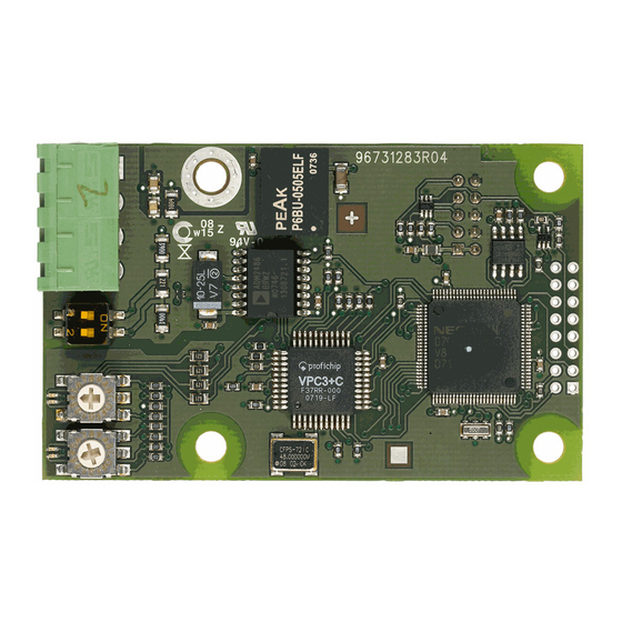
(pos. 3). For maximum safety and reliability, connect the cable screen to earth via the earth clamp, and Note make sure that all CIM 150 units are properly earthed via the mains supply earth wire. Fig. 4 CIM 150 PROFIBUS module Pos. -
Page 7: Setting The Profibus Address
GENIbus communication between the Constantly green CIM 150 and the Grundfos product is OK. A restart of the CIM 150 has to be performed for a PROFIBUS The CIM 150 does not support the Constantly red address change to take effect. -
Page 8: Profinet Io, Cim 500 Setup
6. PROFINET IO, CIM 500 setup 6.2 Setting the Industrial Ethernet protocol The CIM 500 Ethernet module has a rotary switch for selection of 6.1 Connecting the Ethernet cable the Industrial Ethernet protocol. See fig. 11. Warning The CIM 500 must only be connected to SELV or SELV-E circuits. -
Page 9: Establishing Connection To The Web Server
Red/green status LED (LED1) for Ethernet communication • Red/green status LED (LED2) for internal communication Green off No Ethernet link on RJ45 connector. between the CIM 500 and the Grundfos product. Green on Ethernet link on RJ45 connector is OK. LED1 Status Description The CIM 500 is switched off. -
Page 10: Detailed Description Of Data Modules
Description Control bits with a state event trigger behave like a "state" that is Boolean forced upon the DDD system. In the CIM 150/500, the "actual state" of the DDD system as read from the StatusModule is Integer 8 continuously compared with the "requested" state in the... - Page 11 DDD sensor data. H: Pressure (head) Q: Flow Important: When using the CIM 150/500 with the DDD system, the following limitations in the setup of the primary sensor (feedback sensor) apply: • Only sensor 1 (AI1) can be used as primary sensor.
- Page 12 7.2.4 Explanation to operating mode Control enumeration for selection of the remote operating mode. AutoControl This is the normal mode and cannot be changed. The DDD system is controlled according to the selected control mode and setpoint. See section 7.2.3 Explanation to control mode.
- Page 13 7.2.6 Explanation to status module ResetFaultAck Acknowledge bit belonging to the ResetFault control bit. It will be AccessMode set when the control bit is set and the command has been Status bit indicating whether the DDD system is controlled from executed.
-
Page 14: Illustration Of Closed-Loop Control
7.3 Illustration of closed-loop control Setpoint (output) UserSetpoint ActualSetpoint Setpoint RelativePerformance Closed-loop Hydraulic influence control system ProcessFeedback Sensor Feedback/primary sensor value Fig. 15 Illustration of closed-loop control 7.4 Direct bus control of pumps (ControlPumps, module 2) With this module it is possible to individually force each of the six zone pumps to stop. -
Page 15: Status Module (Statusmodule, Module 16)
7.8 Status module (StatusModule, module 16) The status module is a PROFIBUS/PROFINET input module used for reading the status from DDD systems. Its data type is 10, non-standard. Byte Name AccessMode OnOff Byte 1 Fault (data type 5) Warning 4-7 - 0-1 - CopyToLocal ResetFaultAck... -
Page 16: Alarms And Warnings
7.9 Alarms and warnings Reset Action Code Alarm/warning description type type Module Name Description External fault signal Prog. WarningCode Code for DDD system warning. Communication fault, pump None FaultCode Code for DDD system alarm. Hardware fault, IO 351 pump None In the WarningCode module, the cause of a DDD system warning module can be read. -
Page 17: System Measurement Modules
This is measurement data that can be read in the DDD. PROFIBUS/PROFINET direction: Inputs. Data Module Name Unit Description type Grundfos-specific warning code. WarningCode For a list of warning codes, see section 7.9 Alarms and warnings. Grundfos-specific alarm code. FaultCode For a list of alarm codes, see section 7.9 Alarms and... - Page 18 Data Module Name Unit Description type Provides the status of the external digital inputs. Logical "0": The input is 0 V. Logical "1": The input is 5 V. 0: Digital input 1 1: Digital input 2 DigitalInputs Bits 2: Digital input 3 3: Digital input 4 4: Digital input 5 5: Digital input 6...
-
Page 19: Zone Pump Measurement Data Modules
All the data items ControlModule. setpoint, StatusModule. ProcessFeedback, ActualSetpoint and UserSetpoint have a scaling relative to the feedback sensor. By using the scaling information of the feedback sensor (FeedbackSensorUnit, FeedbackSensorMin, FeedbackSensorMax), these data items can be expressed in absolute units. Many of the DDD system measurement modules require a particular sensor to be present. - Page 20 Code Alarm/warning description Code Alarm/warning description Signal fault, LiqTec sensor Leakage current Signal fault, analog input A1 Missing phase Signal fault, analog input A2 External fault signal Signal fault, analog input A3 Too many restarts Signal fault, temperature sensor 2 (t_mo2) Too many restarts per 24 hours Signal fault, temperature sensor 3 (t_mo3) Too many hardware shutdowns...
-
Page 21: Device Identification (Deviceidentification, Module 40)
1: Smart Digital Dosing, DDA 1: With 3-phase pumps 39:Hydro Multi-E model H 2: With 1-phase pumps UnitType [enumeration] According to description above. UnitVersion [enumeration] Used by Grundfos. CIMSoftwareVersion [number] CIMSoftwareRevision [number] CIMModel [enumeration] 7.13 DDD sensor data module Byte Name... -
Page 22: Product Simulation
PROFIBUS/PROFINET master application program (e.g. PLC program) before the equipment is installed under real-life conditions. 8.1 CIM 150 product simulation Product simulation mode is entered when the hexadecimal address switch has one of the values shown in the table below: Address setting (section 5.4 Setting the PROFIBUS... -
Page 23: Fault Finding
9. Fault finding 9.1 CIM 150 Faults in a CIM 150 PROFIBUS module can be detected by observing the status of the two communication LEDs. See the table below. 9.1.1 LED status CIM 150 fitted in a Grundfos DDD system... -
Page 24: Profibus Address
10. PROFIBUS address Decimal to hexadecimal conversion table for setting of the PROFIBUS address switches. See section 5.4 Setting the PROFIBUS address. PROFIBUS address PROFIBUS address PROFIBUS address Subject to alterations. - Page 25 11. Grundfos alarm and warning codes This is a complete list of alarm and warning codes for Grundfos products. For the codes supported by booster systems, see the Alarms and warnings section. Code Description Code Description Code Description Signal fault, PTC sensor (short-...
- Page 26 Code Description Code Description Code Description Gas in pump head, deaerating Run capacitor, low (single-phase Soft pressure build-up time-out problem motors) Signal fault, outdoor temperature Discharge valve leakage Pilot pump alarm sensor Signal fault, air temperature Alarm, general-purpose sensor Suction valve leakage sensor high Signal fault, shunt relative...
- Page 27 Code Description Code Description Code Description Signal fault, temperature sensor 2 Fault, speed plug User-defined event 3 (t_mo2) Signal fault, temperature sensor 3 Functional fault, add-on module User-defined event 4 (t_mo3) Signal fault, Smart trim gap SMS data from DDD sensor not Hardware fault, type 2 sensor received within time...
- Page 28 Appendix The appendix describes the parts of the CIM 500 web server needed for the configuration of a PROFINET IO Ethernet connection. For other CIM 500 web server features, not specifically related to PROFINET IO, see the installation and operating instructions for the CIM 500. A.1 How to configure an IP address on your PC For connecting a PC to the CIM 500 via Ethernet, the PC must be set up to use a fixed (static) IP address belonging to the same...
- Page 29 Enter password. Default: Grundfos. User name and password can be changed on the Note web server under "Grundfos Management". A.4 PROFINET IO configuration This web page is used to configure all the parameters relevant to the PROFINET IO protocol standard. All settings can also be...
- Page 31 GRUNDFOS Pumps (Hong Kong) Ltd. Telefax: +64-9-415 3250 Turkey «Порт» Unit 1, Ground floor GRUNDFOS POMPA San. ve Tic. Ltd. Sti. Norway Тел.: +7 (375 17) 286 39 72/73 Siu Wai Industrial Centre Gebze Organize Sanayi Bölgesi Факс: +7 (375 17) 286 39 71 29-33 Wing Hong Street &...
- Page 32 98547760 0816 ECM: 1182199 www.grundfos.com...
Need help?
Do you have a question about the CIM 150 and is the answer not in the manual?
Questions and answers