Grundfos CIM 200 User Manual
Hide thumbs
Also See for CIM 200:
- User manual (94 pages) ,
- Functional profile and user manual (64 pages) ,
- Instructions manual (52 pages)

Related Manuals for Grundfos CIM 200


Summary of Contents for Grundfos CIM 200
- Page 1 GRUNDFOS INSTRUCTIONS Modbus for Grundfos pumps CIM/CIU 200 Modbus RTU CIM/CIU 260 3G/4G cellular CIM/CIU 500 Ethernet for Modbus TCP Functional profile and user manual...
- Page 3 Modbus for Grundfos pumps English (GB) Functional profile and user manual ............4...
-
Page 4: Table Of Contents
CIM 500 Modbus TCP......6 14.1 CIM 200 ....... 42 Specifications . -
Page 5: Notes
1.2 Notes Domain Name System. Used to resolve host names to IP addresses. The symbols and notes below may appear in Grundfos installation and operating instructions, safety instructions and service GENIbus Proprietary Grundfos fieldbus standard. instructions. GENIpro Proprietary Grundfos fieldbus protocol. -
Page 6: System Description
3.3 CIM 260 3G/4G cellular Modbus 3.1 Modbus The system diagrams provide an overview of the different technologies and how to connect the module or unit to the Grundfos Cellular E pump that you connect to a Modbus network. CIM solution... -
Page 7: Specifications
Related information 5.5 Status LEDs 4.2 CIM 200 Modbus RTU The table below provides an overview of the specifications for Grundfos CIM 200 and CIU 200. For further details, refer to the specific sections of this functional profile. Modbus RTU specifications... -
Page 8: Cim 260 3G/4G Cellular
4.3 CIM 260 3G/4G cellular The table below provides an overview of the specifications for Grundfos CIM/CIU 260. For further details, refer to the specific sections of this functional profile. Modbus cellular specifications Description Comments Data protocol Modbus TCP Data connection uses Modbus TCP. -
Page 9: Cim 200 Modbus Rtu Setup
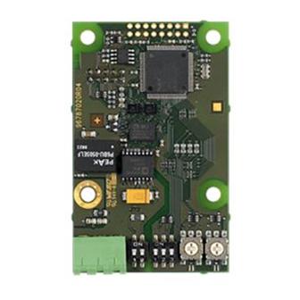
5. CIM 200 Modbus RTU setup 5.1 Setting the Modbus transmission speed Set the transmission speed correctly before the CIM 200 Modbus module is ready to communicate with the Modbus network. Use DIP switches SW4 and SW5 for setting the transmission speed. -
Page 10: Setting The Stop Bits And The Parity Bit
Setting the Modbus address • 1 stop bit. The default setting of the CIM 200 Modbus module is even parity (1 For a complete overview of Modbus addresses, see stop bit). It is possible to change the parity using DIP switch SW3. -
Page 11: Status Leds
Description CIM 200 has been switched off. No internal communication between CIM 200 and Flashing red the Grundfos product. CIM 200 does not support the Grundfos product Permanently red 5 7 6 connected. Internal communication between CIM 200 and the... - Page 12 • Only insert the approved Grundfos battery pack (order no. 99499908). • Never use this battery pack in other battery chargers.
-
Page 13: Status Leds
No communication between CIM 260 and the Flashing red Grundfos product. CIM 260 does not support the connected version of Permanently red the Grundfos product. The connection between CIM 260 and the Grundfos Permanently green product is OK. Example of Ethernet connection Pos. Description... -
Page 14: Setting The Industrial Ethernet Protocol
No internal communication between CIM 500 Flashing red and the Grundfos product. 7.3 Setting the IP addresses CIM 500 does not support the Grundfos Permanently red product connected. The CIM 500 Ethernet module is by default set to a fixed IP address. -
Page 15: Data And Link Leds
7.6 DATA and LINK LEDs The CIM 500 Ethernet module has two connectivity LEDs related to each RJ45 connector. DATA1 and DATA2 These yellow LEDs indicate data traffic activity. Status Description Yellow off No data communication on the RJ45 connector. Yellow flashing Data communication ongoing on the RJ45 connector. -
Page 16: Modbus Register Addresses
0: No parity (default) 1: Even parity 00009 SoftwareDefinedParity ● 2: Odd parity. Note that for CIM 200, this value is used only when you set the transmission speed to "Software-defined" on DIP switches SW4 and SW5. Otherwise, CIM 200 ignores it. - Page 17 ● 2: 2 stop bits. Note that for CIM 200, this value is used only when you set the transmission speed to "Software-defined" on DIP switches SW4 and SW5. Otherwise, CIM 200 ignores it. PIN code for SCADA systems, etc.
-
Page 18: Cim Status Register Block
Holds a data error counter for the GENIbus connection to the E-pump. ● ● ● 00023 VersionNumber A Grundfos-specific version number. BCD coded unsigned integer value. ● ● ● Holds the current Modbus slave address of the device. 00024 ActualModbusAddress ●... -
Page 19: Cellular Network Real Time Clock
Address Register name Description CIM 200 CIM 260 CIM 500 State of CIM 260 module battery 0: Battery not present 1: Battery must be replaced 2: Battery charging 00033 BatteryState 3: Battery needs charging, but temperature too high ● 4: Battery needs charging, but temperature too low... -
Page 20: Pump Control Register Block
9.5 Pump control register block Registers in this block can be read by means of function codes 0x03 and/or 0x04. They can be written as holding registers with function codes 0x06 and 0x10. Address Register name Description Control bit that sets local or remote control. 0: Local Bit 0: RemoteAccessReq 1: Remote (controlled by Modbus master). - Page 21 Address Register name Description RelayControl A register to control the relays. It is bitwise interpreted as follows: Controls the state of relay 1. 0: Closed Bit 0: Relay1Control 1: Open Only E-pumps and CUE. Controls the state of relay 2. 0: Closed Bit 1: Relay2Control 1: Open...
-
Page 22: Pump Status Register Block
9.6 Pump status register block Registers in this register block can be read by means of function codes 0x03 and/or 0x04. They are read-only. Address Register name Description Indicates if the state of "Low Flow Stop" function is active or not active. 0: Pump is not in "Low Flow Stop"... - Page 23 4: OpenLoopMin (running at minimum speed) 6: OpenLoopMax (running at maximum speed). 7: Hand mode 00205 AlarmCode The Grundfos-specific alarm code. 00206 WarningCode The Grundfos-specific warning code. Indicates the number of months until the next bearing service (not available on all E-pumps).
- Page 24 Only available on MAGNA3 and MGE model H and later. Actual selection between Direct/Inverse control. 0: Inverse control 00224 DirectControl 1: Direct control Only available on MAGNA3 and MGE model H and later. Related information 9.2 CIM configuration register block 17. Grundfos alarm and warning codes...
-
Page 25: Pump Data Register Block
9.7 Pump data register block Registers in this block can be read by means of function codes 0x03 and/or 0x04. They are read-only. The table below shows which registers each E-pump type supports. Unless otherwise stated, the data type used for counters and scaled values is always an unsigned integer. Table legend 3-ph: 3-phase only. - Page 26 Direct measurement, where an analog or temperature input has been configured to Remote differential temperature RemoteDiffTemp (register 00346). • PumpLiquidTemp (register 00322) measured by build-in Grundfos sensor and RemoteTemp2 (register 00337) measured by analog or temperature input. • RemoteTemp1 (register 00320) and RemoteTemp2 (register 00337) measured by analog or temperature input.
-
Page 27: Sensor-Dependent Measurements
9.8 Sensor-dependent measurements Many of the measurement registers require a particular sensor to be present. Because a limited number of sensors are available, only a few of the "S" marked data modules are available simultaneously. The following sections describe the relation between available Modbus measurement registers and the setup of sensors. The description is split into sections for different pump types, because the approach varies. -
Page 28: Alarm Simulation Register Block (Not Cue)
E-pump models H and later Measured parameters (selected from display or handheld) Grundfos built-in Grundfos LiqTec Mapped to Modbus register sensor sensor Analog input AI1, AI2, Temperature Pt100 input Parameter T1, T2 Pump inlet pressure ● InletPressure (00315) Pump inlet diff. press ure ●... -
Page 29: Detailed Descriptions Of Registers
10. Detailed descriptions of registers 10.1 Control mode The supported control modes are described further in this section. The control mode is set with register 00102 and its status can be read from register 00203. Control modes Description Illustration Open loop The setpoint of the E-pump is interpreted as the setpoint for the >... -
Page 30: Setpoint In Closed-Loop Control
00212 NomFrequency. The selected setpoint is reflected in register 00338 UserSetpoint with the same scaling. From The actual setpoint, whether it has been set via Grundfos GO, the fieldbus, it will get whatever value written to Setpoint. From pump... -
Page 31: Alarms And Warnings
10.4 Alarms and warnings Address Name Description Code Alarm/warning description 00206 WarningCode Code for E-pump warning. Motor bearing temperature high (Pt100) in non-drive end (NDE) 00205 FaultCode Code for E-pump alarm. Inrush fault Communication fault, internal frequency converter module In the WarningCode register, the cause of an E-pump warning can Real time clock error be read. -
Page 32: Modbus Rtu Commissioning, Step-By-Step Guides
11.1 Hardware setup, CIM 200 Step Action Install CIM 200 in the Grundfos product according to the product documentation. Complete the product configuration, for example sensor configuration. This can be done either on the pump control panel, via Grundfos GO. -
Page 33: Hardware Setup, Ciu 260 Data Connection
11.4 Hardware setup, CIU 260 data connection Step Action Connect the GENIbus cable from CIU 260 to the Grundfos product. See the CIU quick guide instruction. Fit an antenna to the CIM module SMA connector. Insert the SIM card in CIM 260. -
Page 34: Ciu 500 Modbus Tcp Communication Setup
Log on to the webserver. Default: User: admin Password: Grundfos. In the menu column to the left select: Configuration > Real time Ethernet protocol Type in an IP address belonging to the same subnet as your PC, for example 192.168.1.2. - Page 35 "Connected": A client has established a socket connection. The system is ready for TCP/IP data exchange, or already exchanging data. For details about the use of SMS commands, see "CIM 260 SMS commands", which you can download from Grundfos Product Center.
- Page 36 3. CIU 260 is now ready for a client, for example the SCADA system, to establish a socket connection and begin TCP/IP data exchange. When a client connects CIU 260, the connection state will change to "Connected", and the cellular connection status LED1 indicates when data transfer takes place.
-
Page 37: Modbus Rtu Telegram Examples
Pos. Description Clients SCADA system PC Tool, etc. GRE router VPN tunnel Internet Cellular operator Cellular network Base station APN "Static" IP address CIU 260 with CIM 260 module and SIM card Cellular network Setup, status and control commands via SMS Mobile phone Related information 5.5 Status LEDs... -
Page 38: Read Input Registers, 0X04
13.3 Read input registers, 0x04 13.4 Write single register, 0x06 This function is used for reading input registers from the slave. Input This function is used for writing a single holding register in the registers are read-only registers by definition. The request telegram slave. -
Page 39: Diagnostics, 0X08
Only supported by CIM 200 Modbus RTU. The diagnostics register is interpreted as follows: This function provides a test for checking the communication system between the master and the Grundfos slave. It contains a Bit Description single-byte subcode to identify the test to be performed. -
Page 40: Reading The Cim Configuration Register Block
13.9 Reading the CIM configuration register block 13.10 Setting the setpoint This section shows how to read the first four registers of the CIM This section shows how to set a new setpoint (reference). configuration register block. In the example, slave address 0x01 is used, and a value of 55 % In the example, slave address 0x01 is used. -
Page 41: Starting The E-Pump
13.12 Starting the E-pump 13.13 Stopping the E-pump This section shows how to start the E-pump. This section shows how to stop the E-pump. In the example, slave address 0x01 is used. In the example, slave address 0x01 is used. Set the ControlRegister to the following values: Set the ControlRegister to the following values: Bit 0:... -
Page 42: Fault Finding The Product
14. Fault finding the product 14.1 CIM 200 You can detect faults in CIM 200 by observing the status of the two communication LEDs. Related information 3.2 CIM 200 Modbus RTU 14.1.1 LED status CIM 200 fitted in a Grundfos E-pump... - Page 43 Possible cause Remedy • Check the visual diagnostics on the Modbus slave. Is the Grundfos GENIbus LED flashing green and the Modbus LED off or flashing green? • Ensure that the cable between the Modbus master and the Modbus slave is connected correctly. See section...
-
Page 44: Cim/Ciu 260
Fault (LED status) Possible cause Remedy Ensure that CIM 260 is fitted and connected CIM 260 is fitted incorrectly in the Grundfos E-pump. Both LED1 and LED2 remain off when the power correctly. supply is connected. CIM 260 is defective. - Page 45 14.2.2 CIM/CIU 260 3G/4G cellular communication faults Fault Possible cause Remedy • Ensure that CIU 260 has connection to the cellular network. LED1 must be pulsing yellow. If the LED1 signal is incorrect, see section 260 3G/4G cellular Modbus setup for correct installation of the CIM 260.
-
Page 46: Cim 500
Fault (LED status) Possible cause Remedy CIM 500 is fitted incorrectly in the Grundfos product. Check that CIM 500 is fitted and connected correctly. Both LED1 and LED2 remain off when the power supply is connected. CIM 500 is defective. - Page 47 Register 00201 bit 8 writing of settings. Remote). The E-pump should show "Controlled from AccessMode must be "1" (=Remote) for bus control bus" when status is read in Grundfos GO. to be active. Related information 7.1 Connecting the Ethernet cable 7.3 Setting the IP addresses...
-
Page 48: Modbus Rtu Rotary Switch Addresses
15. Modbus RTU rotary switch addresses Modbus Modbus Modbus Modbus Modbus address address address address address Example: To set the slave address to the value 142, set the rotary It is very important to ensure that two devices do not have switches SW6 and SW7 to "8"... -
Page 49: Disposing Of The Product
This product or parts of it must be disposed of in an environmentally sound way. 1. Use the public or private waste collection service. 2. If this is not possible, contact the nearest Grundfos company or service workshop. The crossed-out wheelie bin symbol on a product means that it must be disposed of separately from household waste. -
Page 50: Grundfos Alarm And Warning Codes
17. Grundfos alarm and warning codes This is a complete list of alarm and warning codes for Grundfos products. For the codes supported by this product, see the alarms and warnings section. Code Description Code Description Code Description Leakage current... - Page 51 Code Description Code Description Code Description Start capacitor, low Auxiliary winding current too high (single- Auxiliary winding current too low (single- phase motors) phase motors) (single-phase motors) Run capacitor, low (single-phase motors) Signal fault, outdoor temperature sensor Signal fault, air temperature sensor Signal fault, shunt relative pressure Strainer clogged sensor...
- Page 52 Code Description Code Description Code Description User-defined relay has been forced Fault, On/Off/Auto switch Pump continuous runtime too long (manually operated or commanded) Power-on notice, (device or system has Fault, battery/UPS User-defined event 1 been switched off) User-defined event 2 User-defined event 3 User-defined event 4 SMS data from DDD sensor not received...
- Page 53 Appendix A A.1. Webserver configuration The built-in webserver offers easy monitoring of the CIM 500 module and makes it possible to configure the selected Industrial Ethernet protocol. Using the webserver, you can also update the firmware of the CIM 500 module and store or restore settings, among other functions. To connect a PC to CIM 500, proceed as follows: 1.
- Page 54 Object Description Enter username. Username Default: admin. Enter password. Default: Grundfos. After the first log in, you are forced to change the password. The password must contain: • at least 8 and maximum 20 characters • at least one lower case letter Password •...
- Page 55 A.3. Modbus TCP configuration This web page is used to configure all the parameters relevant to the Modbus TCP protocol standard. Real Time Ethernet Protocol Configuration - Modbus TCP Object Description The default value is 502, the official IANA-assigned Modbus TCP port number. The number 502 is always active implicitly. TCP Port Number If you select another value in the webserver configuration field, both the new value and value 502 will be active.
- Page 56 A.5. Update You can update the firmware by means of the built-in webserver. The binary file is supplied by Grundfos. To make installation and configuration easier, you can upload the configuration to a PC for backup or distribution to multiple modules.
- Page 57 Object Description Firmware Path to binary firmware image that can be used for updating the module. Update Click [Update] to start the update. The procedure takes approximately one minute. File Path to the configuration file. Download to module Click here to transfer the configuration file to the module. Upload from device Click here to upload the configuration of the module to a file on your PC.
- Page 58 Tel.: +387 33 592 480 Centre Turkey Fax: +387 33 590 465 29-33 Wing Hong Street & 68 King Lam GRUNDFOS Pumper A/S GRUNDFOS POMPA San. ve Tic. Ltd. Sti. www.ba.grundfos.com Street, Cheung Sha Wan Strømsveien 344 Gebze Organize Sanayi Bölgesi E-mail: grundfos@bih.net.ba...
- Page 59 98367081 03.2023 ECM: 1360614 www.grundfos.com...
Need help?
Do you have a question about the CIM 200 and is the answer not in the manual?
Questions and answers