Avaya IP Office Installation Manual
Hide thumbs
Also See for IP Office:
- Installation manual (406 pages) ,
- Manual (324 pages) ,
- User manual (210 pages)
Table of Contents
Advertisement
Quick Links
Advertisement
Table of Contents

Related Manuals for Avaya IP Office


Summary of Contents for Avaya IP Office
- Page 1 IP Office Installation Manual 40DHB0002UKCL – Issue 3 (5/12/2001)
-
Page 2: Table Of Contents
Page 2 - Contents Contents Introduction..............23 Introduction ..............3 Programming Tools ............23 General ................3 PC to IP Office LAN Port Connection .........23 Scope of Manual ...............3 Initial Programming............24 Safety and Homologation Statements.......3 Telephone Installation..........25 Lithium Batteries..............3 Further Information and Product Updates ......3... -
Page 3: Introduction
See page 34 for wiring details on a 4450DSS module. Safety and Homologation Statements For Declarations of Conformity, Safety Requirements, Approval and Regulatory Instructions for Use of the IP Office systems, refer to the Approvals folder contained in the CD shipped with each system. Lithium Batteries A lithium battery is fitted to the real time clock on the IP403 and IP406 mother boards. -
Page 4: Ip403 Office Platform
An eight port auto-negotiating 10/100 BaseT LAN hub provides access to networks and/or up to eight IP Office telephones. (Where IP Office telephones are to be used, the hub should be connected to a suitable switch, i.e. an Avaya Cajun P130.) -
Page 5: Ip403 Office - Front View
- DT ports are for connection to Avaya 2000 series telephones (see page 3). - DS ports are for connection to Avaya 4400 and/or 6400 series telephones (see page 3). Both ports can be encoded for either µ-Law or A-Law PCM encoding. -
Page 6: Ip403 Office - Rear View
A single 3.5mm stereo or mono jack socket that enables input from an external 'Music-on- Hold' source. Port Pinouts and Cables For Port Pinouts and Cables, refer to pages 30 and 33 respectively. Page 6 - IP403 Office Platform Installation Manual 40DHB0002UKCL – Issue 3 (5/12/2001) IP Office... -
Page 7: Ip406 Office Platform
See page 19 for installation and page 14 for country specific variants. An eight port auto-negotiating 10/100 BaseT LAN hub provides access to networks and/or up to eight IP telephones. (Where IP telephones are to be used, a suitable switch, i.e. an Avaya Cajun P130 should be used) -
Page 8: Ip406 Office - Front View
IP406 Office platform for both data and Voice over IP (VoIP) calls. (Where IP telephony is required, the hub must be connected to a suitable switch, i.e. an Avaya Cajun P130.) This eight port auto-negotiating 10/100 BaseT LAN hub supports a single MAC address only (printed on the base of the module). -
Page 9: Ip406 Office - Rear View
A single 3.5mm stereo or mono jack socket that enables input from an external 'Music-on- Hold' source. Port Pinouts and Cables For Port Pinouts and Cables, refer to pages 30 and 33 respectively. Installation Manual IP406 Office Platform - Page 9 IP Office 40DHB0002UKCL – Issue 3 (5/12/2001) -
Page 10: Expansion Modules
Dependant upon configuration requirements, combinations of the following Expansion Modules are used with IP Office platforms. With the exception of the WAN3 module (see page 13), all of these Expansion Modules are connected to the Expansion Ports of an IP Office platform using Expansion Interconnect Cables (see page 39). -
Page 11: Ip400 Digital Stations 16/30
IP400 Digital Stations 16/30 The IP400 Digital Station Expansion Module similar to the IP400 Digital Terminal Expansion Module (see page 10) with the exception that the Ports are labeled DS not DT and support Avaya 6400 or 4400 series telephones. -
Page 12: Ip400 So8
24V DC Port connections • Expansion Port Used to connect a So8 Module to the Expansion Ports of an IP Office platform. • DC Power I/P Socket Socket for the external 24V DC unregulated power supply (supplied with kit). • DTE Port A 25-way D-type socket. -
Page 13: Ip400 Wan3
The LAN Port is the expansion port and permits connection to a IP403/6 Office platform LAN Port without the need for a cross over cable. A LAN Interconnect cable (see page 36) is used for connection to an IP Office platform. Rear View... -
Page 14: Country Variants
2. PRI T1 supports both ISDN and Analog emulation. The default setting is 23B+1D and is switchable in the installation software to become a 24B trunk. Page 14 - Country Variants Installation Manual 40DHB0002UKCL – Issue 3 (5/12/2001) IP Office... -
Page 15: Integral Module Kits
IP400 So8 Variant Country SAP Code IP400 So8 700185077 IP400 WAN3 Variant Country SAP Code IP400 WAN3 700185028 Note: For countries outside the Americas, use ROW variant. Installation Manual Country Variants - Page 15 IP Office 40DHB0002UKCL – Issue 3 (5/12/2001) -
Page 16: Preparing For Installation
Preparing for Installation Preparing for Installation Introduction This section reviews the requirements for installing an IP Office system. You must meet these requirements for the system to operate safely and in the intended manner. This section covers : – "Tools & Parts Required" on page 16. -
Page 17: Environmental Requirements
50/60Hz, 100-240V power source only. – UPS Equipment : The use of UPS's to support the IP Office system during mains power failure is highly recommended. Such equipment also provides mains conditioning. Contact your distributor for details of preferred and tested suppliers and models. -
Page 18: Installing A New System
6. Install all telephones in their appropriate locations. For wall mounting, see page 26. 7. Connect your PC LAN Port to one of the LAN Ports on the front of a IP Office base module using a LAN Cable (see page 37). -
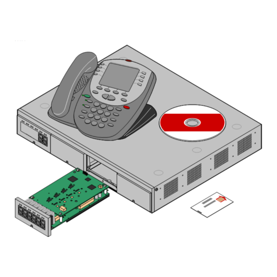
Page 19: Installation Of Integral Modules
Installing a New System Initial Assembly - Page 19 Installation of Integral Modules To install an integral module in a IP Office system, follow the pictorial instructions given below: Trunk Interface Modules (BRI/PRI/ANALOG4) For IP403 Office trunks modules see page 6. - Page 20 Page 20 - Initial Assembly Installing a New System Voice Compression Module (VCM) An optional Voice Compression Module (see pages 4 and 7) is fitted to a IP Office base unit as follows: Procedure 1. Remove the three fixing screws on the rear of cover. Turn the unit over and remove the four fixing screws from the base.
- Page 21 Initial Assembly - Page 21 Dual Modem Module An optional Dual Modem Module (see pages 4 and 7) is fitted to a IP Office base unit as follows: Procedure 1. Remove the three fixing screws on the rear of cover. Turn the unit over and remove the four fixing screws from the base.
-
Page 22: Rack Mounting Assembly Instructions
Page 22 - Initial Assembly Installing a New System Rack Mounting Assembly Instructions IP Office modules can be mounted in any standard 19" rack as follows: Page 22 - Installing a New System Installation Manual 40DHB0002UKCL – Issue 3 (5/12/2001) -
Page 23: Basic System Programming
IP Office system. The IP Office hub port can be connected in two ways; either directly to a PC or as part of a LAN. Both methods use an IP Office Cat. 5E patch cable (see page 35) connected between one of the LAN hub ports on the front of the IP Office base unit and the PC. -
Page 24: Initial Programming
Basic System Programming Initial Programming All the software used to configure and manage the IP Office system must be installed on your PC from the supplied Administration CD. With the initial assembly completed (see page 18) and your PC connected to the IP Office system, insert and run the Administration CD. From the initial 'Welcome' screen, click on Next. -
Page 25: Telephone Installation
3. With power to the IP Office system switched on, make a test call. 4. Switch the power to the IP Office system off and again make a test call. 5. Switch the power to the IP Office system back on again. -
Page 26: Wall Mounting 2000 Series Telephones
Telephone Installation Wall Mounting 2000 Series Telephones Mounting brackets exist which clip onto the base on IP Office telephones. These brackets (two required per telephone) can be used to either raise the desk position of the telephone or for wall mounting. -
Page 27: Wall Mounting 44/4600 & 6400 Series Telephones
The following pictorial instructions, although for a 4600 telephone, provide a general overview on how to wall mount both series of telephones. For safety instructions and details, refer to the specific instructions for each telephone type (supplied on the CD with the IP Office system). Installation Manual... -
Page 28: System Handover
– Where a Feature Key has been used (for software requiring a license), record it's physical location (location of the PC is it plugged into) and leave a record of such on site with the system. Page 28 - System Handover Installation Manual 40DHB0002UKCL – Issue 3 (5/12/2001) IP Office... -
Page 29: Technical Data
The system must be configured for Point to Multi point connection to comply with Austel requirements for connecting to TS013 circuits. As the IP Office does not support emergency dialing after loss of power, the following warning notice should be recognized: WARNING This equipment will be inoperable when mains power fails. -
Page 30: Port Pinouts
Technical Data Port Pinouts This section provides the technical specifications for the IP Office ports with the exception of the USB port and cable. The USB port and cable (up to 5 meters) are standard. Refer to page 33 for cable details. -
Page 31: Lan Port - 10/100 Baset
V35 TxClk-A V35 RxClk-B V35 RxClk-A CHASSIS Note: For the USA, only FCC Part 68 registered data circuit terminal equipment should be connected to the WAN Ports. Installation Manual Technical Data - Page 31 IP Office 40DHB0002UKCL – Issue 3 (5/12/2001) -
Page 32: Audio Port (3.5Mm Stereo Jack Socket)
Pin 1 and Pin 3, ensure that Pin 1 is at a positive voltage with respect to Pin 3. Each circuit can be switched independently. Switch Setting Information Low resistance between Pins. High resistance between Pins. Page 32 - Technical Data Installation Manual 40DHB0002UKCL – Issue 3 (5/12/2001) IP Office... -
Page 33: Cables
Cables - Page 33 Cables This section provides information about the cables that are used with IP Office. Refer to page 30 for port pinout details. CAUTION: All ISDN and WAN cables should not be longer than 5 meters in length. -
Page 34: Dt Line Cord For Structured Cabling
This cable can be used to replace the RJ11 to BT Newplan plug that is attached to the 20 series telephones to allow connection to structured cabling. Page 34 - Technical Data Installation Manual 40DHB0002UKCL – Issue 3 (5/12/2001) IP Office... -
Page 35: Pri/Bri Isdn Cable
Technical Data Cables - Page 35 PRI/BRI ISDN Cable SAP Code:- 700213440 Supply: As standard with IP Office systems. One cable per ISDN port. A RJ45 Plug. B RJ45 Plug. C Cat 5 UTP cable - RED. D 3 meters. -
Page 36: Lan Interconnect Cable
This cable is used: When connecting IP Office hub ports 1 - 7 directly to a PC. When connecting a WAN3 to a IP Office hub port which is located in the same cabinet as the IP Office. Pins 4,5,7 and 8 are through connected for ease of construction. They are not actually used. -
Page 37: Lan Cable
This cable is used: When connecting IP Office hub ports 1 - 7 directly to a PC. When connecting a WAN3 port to a IP Office hub port which is not located in the same cabinet as the IP Office. -
Page 38: Lan Crossover Cable
Cable Notes End B White/Orange Twisted Pair Orange/White White/Green Twisted Pair Green/White This cable is used when connecting Hub Ports 1 - 7 directly to another Hub. Page 38 - Technical Data Installation Manual 40DHB0002UKCL – Issue 3 (5/12/2001) IP Office... -
Page 39: Expansion Interconnect Cable
Clock-B White/Blue Tx-A White/Brown Twisted Pair8 Tx-B Brown/White The RJ45 Plug Shell at each end of the cable is connected to the STP Cable Drain Wire. Installation Manual Technical Data - Page 39 IP Office 40DHB0002UKCL – Issue 3 (5/12/2001) -
Page 40: V.24/V.28 Wan Cable
Pin 19 at end A is connected to the Screened Cable Drain Wire. The maximum core to core capacitance must not exceed 800pF. This cable is used to connect a WAN port to a Digital leased Line. Page 40 - Technical Data Installation Manual 40DHB0002UKCL – Issue 3 (5/12/2001) IP Office... -
Page 41: X.21 Wan Cable
Pin 19 at end A is connected to the Screened Cable Drain Wire. This cable is used to connect a WAN port to a Digital leased Line. Installation Manual Technical Data - Page 41 IP Office 40DHB0002UKCL – Issue 3 (5/12/2001) -
Page 42: Wan Cable
Pin 19 at end A is connected to the Screened Cable Drain Wire. The maximum core to core capacitance must not exceed 800pF. This cable is used to connect a WAN port to a Digital leased Line. Page 42 - Technical Data Installation Manual 40DHB0002UKCL – Issue 3 (5/12/2001) IP Office... -
Page 43: Telephone Converter Cables
• Installation of a Contact Closure Adjunct controlled device outside the buuilding requires a 146G Surge Protector – SCL/8 to protect the c ontrol unit from elcetrical surges. Installation Manual Technical Data - Page 43 IP Office 40DHB0002UKCL – Issue 3 (5/12/2001) -
Page 44: Port Safety Classification
Page 44 - Port Safety Classification Technical Data Port Safety Classification The Avaya IP Office systems have the following ports in common: • Expansion ports. • 10/100 BaseT LAN ports. • Telephone ports which are either A-Law encoding or µ-Law encoding. -
Page 45: Technical Specifications
3.5mm Stereo Jack socket. Switching Capacity - 0.7A. Control Maximum Voltage - 55V d.c. On state resistance - 0.7Ω. Short circuit current - 1A. Reverse circuit current capacity - 1.4A. Installation Manual Technical Data - Page 45 IP Office 40DHB0002UKCL – Issue 3 (5/12/2001) -
Page 46: Protocols
DHCP RFC 1533 Dynamic Host Control Protocol. RFC 1541 RFC 1631 Network Address Translation. BOOTP RFC 951 Bootstrap Protocol. TFTP RFC 1350 Trivial File Transfer Protocol Page 46 - Technical Data Installation Manual 40DHB0002UKCL – Issue 3 (5/12/2001) IP Office... -
Page 47: Index
Tools required ................................16 Trunk Modules................................. 6 , 9 Unpacking .................................. 18 UPS Equipment................................17 USB Interface................................6 Ventilation .................................. 17 Voice over IP................................5 , 8 Installation Manual Index - Page 47 IP Office 40DHB0002UKCL – Issue 3 (5/12/2001) - Page 48 Intellectual property related to this product (including trademarks) and registered to Lucent Technologies has been transferred or licensed to Avaya. This document contains propriety information of Avaya and is not to be disclosed or used except in accordance with applicable agreements.
Need help?
Do you have a question about the IP Office and is the answer not in the manual?
Questions and answers