
Related Manuals for ICP DAS USA PM-2133D Series


Summary of Contents for ICP DAS USA PM-2133D Series
- Page 1 PM-2133D User’s Manual v1.00 Last Revised: Feb. 2020 Page: 1 E-mail: service@icpdas.com Copyright © ICP DAS Co., Ltd. All Rights Reserved. www.icpdas.com...
-
Page 2: Table Of Contents
Chapter 1 Introduction ........3 Chapter 4 Wiring Diagrams ......13 1.1. PM-2133D introduction ..3 Connection ...... 13 1.2. Caution ......4 Wiring ......15 1.2.1. Danger ......4 Chapter 5 Keypad, LED Indicator & Display .. 17 1.3. Warning ...... -
Page 3: Chapter 1 Introduction
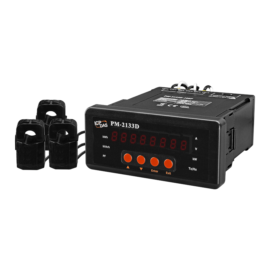
PM-2133D series that gives you access to real-time electric usage for three-phase power measurement. With its high accuracy (<0.5%, PF=1 ), the PM-2133D series can be applied to both low voltage primary side and/or medium/high voltage secondary side and enables the users to obtain reliable and accurate energy consumption readings from the monitored equipments in real time under operation. -
Page 4: Caution
1.2. Caution 1.2.1. Danger The meter contains hazardous voltages, and should never be disassembled. Failing to follow this practice will result in serious injury or death. Any work on or near energized meters, meter sockets, or other metering equipment could induce a danger of electrical shock. -
Page 5: Limitation Of Warranty
1.4.1. Limitation of Warranty This warranty does not apply to defects resulting from unauthorized modification, misuse, or use for reason other than electrical power monitoring. The supplied meter is not a user-serviceable product. PM-2133D User’s Manual v1.00 Last Revised: Feb. 2020 Page: 5 ... -
Page 6: Chapter 2 Specifications
Chapter 2 Specifications 2.1 Specifications Model PM-2133D PM-2133D-MTCP AC Power Measurement Wiring 1P2W-1CT, 1P3W-2CT, 3P3W-2CT, 3P3W-3CT and 3P4W-3CT Measurement Voltage 10 ~ 500 V (CAT III) CTØ10 mm (0.05 A~60 A); CTØ16 mm (0.1 A~100 A); CTØ24 mm (0.15 Measurement Current A~200 A);... - Page 7 Aux Power Input Range +85 ~ +264 VAC (277 VAC available) Power Consumption Dimensions (W x L x H) 110 mm x 50 mm x 115 mm Environment Operating Temperature -20 ~ +70 °C Storage Temperature -25 ~ +80 °C PM-2133D User’s Manual v1.00 Last Revised: Feb.
-
Page 8: Chapter 3 Installation
Chapter 3 Installation 3.1 Inspection The instrument is no longer safe when, a) Shows clear signs of damage b) Does not work c) Long storage under extreme conditions d) Damage during shipment 3.2 Safety Please use the soft dry clothes to clean the instrument. Please do not use any chemical or detergent or volatile solvents to clean the instrument, in order to avoid any possibility of the cover damage. - Page 9 Products come with external split type clip-on CT’s. Disconnect the CT’s or use other CT’s is highly prohibited. Please read this operation manual carefully before using. Please re-confirm the measure position. Meter auxiliary power is +85 ~ +264 VAC (277 VAC available). ...
- Page 10 3.2.2 Mounting 1. Prepare a panel and cut a hole to 92.0 the specified size (unit: mm). 46.0±1 Panel thickness: 1 to 5 mm 2. Remove the latch assembly. i. Press the protruding pin of the latch assembly. The protruding pin PM-2133D User’s Manual v1.00 Last Revised: Feb.
- Page 11 Keep on pressing the protruding pin to slide the latch assembly to the groove The groove 3. Attach the PM-2133D to the cut-out hole. 4. Attach the latch assembly, and then slide the latch assembly toward the panel. PM-2133D User’s Manual v1.00 Last Revised: Feb.
-
Page 12: Ct's Installation Steps
3.2.3 CT’s installation steps At the bottom of the CT, there is a “K→L” mark. Open the CT clip. Make sure the power current Installation steps finished. direction follow the “K→L” mark on the CT and then close the CT clip. PM-2133D User’s Manual v1.00 Last Revised: Feb. -
Page 13: Chapter 4 Wiring Diagrams
Chapter 4 Wiring Diagrams 4.1 Connection Please firstly check the current input terminal, and then in white black, white black, white black wire sequences (CT1-K, CT1-L, CT2-K, CT2-L, CT3-K, CT3-L). Then connect the CT’s, and close the CT clip. Make sure the arrow direction sign on CT’s follows current flow direction K (W)→L(B). - Page 14 Current Input 1. The external CT’s are fragile, please handle with care. 2. The current input of PM-2133D series is in mA range. Only the ex-factory attached CT’s can be used. The other CT’s, for example, from panel will damage the instrument due to its large current (around 5A) 3.
-
Page 15: Wiring
4.2 Wiring 1P2W-1CT(PM-2133D) 1P3W-2CT(PM-2133D) 3P3W-2CT(PM-2133D) PM-2133D User’s Manual v1.00 Last Revised: Feb. 2020 Page: 15 E-mail: service@icpdas.com Copyright © ICP DAS Co., Ltd. All Rights Reserved. www.icpdas.com... - Page 16 3P3W-3CT(PM-2133D) 3P4W-3CT(PM-2133D) PM-2133D User’s Manual v1.00 Last Revised: Feb. 2020 Page: 16 E-mail: service@icpdas.com Copyright © ICP DAS Co., Ltd. All Rights Reserved. www.icpdas.com...
-
Page 17: Chapter 5 Keypad, Led Indicator & Display
Chapter 5 Keypad, LED Indicator & Display 5.1 Function of LED Display, Indicator and Keypad PM-2133D has a built-in 8-Digit LED Display to display the power data measured by the meters. The 7 LED Indicators are used to indicate the type of the power data which are currently shown on the 8-Digit LED Display, and the status of RS-485 communication(Tx/Rx). -
Page 18: Indicator And Keypad
5.2 Operation of LED Display, Indicator and Keypad With the built-in LED Display, Indicator and Keypad, PM-2133D can display the real-time power data it measures. User can also change the setting of the power meter. The following sections describe the features provided. 5.2.1 Normal Mode After power up PM-2133D, the default power data shown is power data of I_a (Phase A Current). -
Page 19: Setup Mode
5.2.2 Setup Mode User can press the buttons of Keypad to enter the Setup Mode to adjust the parameters setting of PM-2133D. The steps are as below: i. Press the "Enter" button to enter the Setup mode, all the LED Indicators of PMD-2133D will be in "ON"... - Page 20 ii. Press the "▲" button and "▼" button of the Keypad to select the parameter of PM-2133D to be modified. The settings of parameters provided by PM-2133D will be shown in sequence as below:. : LED Segment check (read only, cannot be modified) ...
- Page 21 After completing the setting of units digit, press the "Enter" button, the tenths digit of the PT ratio will blink. Press the "▲" button and "▼" button to adjust the setting of tenths digit. After completing the setting of tenths digit, press the "Enter" button, the hundredths digit of the PT ratio will blink.
- Page 22 iv. Repeat Step ii~iii to complete all parameter settings. v. After all parameter settings are completed, press the "Exit" button to return the Normal Mode. PM-2133D User’s Manual v1.00 Last Revised: Feb. 2020 Page: 22 E-mail: service@icpdas.com Copyright © ICP DAS Co., Ltd. All Rights Reserved. www.icpdas.com...
-
Page 23: Chapter 6 Modbus-Rtu Communication
Chapter 6 Modbus-RTU communication 6.1 RS-485 setting About the Modbus Baudrate setting, Modbus Data Format setting and Modbus Address setting, Please refer to "5.3.2 Setup Mode" section for detail. The default setting for RS-485: 19200, n, 8, 1 The default setting for Modbus Address: 6.2 Modbus-RTU setting 6.2.1 Specifications Protocol... - Page 24 Note: the max. data reading of Function 03 and Function04 is 125 registers Data format Integer:16 bits with sign, each with 1 register Unsigned Integer:16 bits without sign, each with 1 register Float:IEEE 754 Format ,each with 2 registers, Low Word is first priority while transmit IEEE 754 Format Definition of the floating format of the Bits...
-
Page 25: Modbus Register
6.2.2 Modbus Register Modbus Module #1 – N/A Modbus Module #2 – Holding Register : System Parameter Setting Modbus Register Data Default Parameter name Range Units Comment Modicom Type value Format PT_Ratio 44100 0x1003 Word UInt 1-65535 0.01 CT_Ratio 44101 0x1004... - Page 26 Modbus Module #3 - Input Register : System Information Modbus Register Data Default Parameter name Range Units Comment Modicom Type value Format 9: 1P2W 10: 1P3W 11: 3P3W2CT Wiring Type 30513 0x0200 Word UInt 12: 3P3W3CT 13: 3P4W 0: Negative Only work (ACB) when 3P4W...
- Page 27 Modbus Module #4 - Input Register :Power value (Float) Modbus Register Parameter Data Type Range Units Comment name Modicom Format 0x1100- 0x1101 34353-34354 DWord Float Volt 34355- 34356 0x1102- 0x1103 DWord Float 34357- 34358 0x1104- 0x1105 DWord Float kW_a 34359- 34360 0x1106- 0x1107 kvar_a...
- Page 28 34417-34418 0x1140-0x1141 PF_tot DWord Float 34419-34420 0x1142-0x1143 kWh_tot DWord Float 34421-34422 0x1144-0x1145 kvarh_tot DWord Float 34423-34424 0x1146-0x1147 kVAh_tot DWord Float 34425-34426 0x1148-0x1149 Freq_a DWord Float 45~65 34427-34428 0x114A-0x114B Freq_b DWord Float 45~65 34429-34430 0x114C-0x114D Freq_c DWord Float 45~65 34431-34432 0x114E-0x114F Freq_max DWord Float...
- Page 29 34649- 34650 0x1228-0x1229 kvar_c DWord Int32 0.1kvar 34651- 34652 0x122A-0x122B kVA_c DWord Int32 0.1kVA 34653 0x122C PF_c Word 0~1000 0.001PF 0~1.000 34654- 34655 0x122D-0x122E kWh_c DWord Int32 ±0~99999999 0.1kWh ±0~9999999.9 34656-34657 0x122F-0x1230 kvarh_c DWord Int32 0~99999999 0.1kvarh 0~9999999.9 34658-34659 0x1231-0x1232 kVAh_c DWord Int32...
- Page 30 34888- 34889 0x1317- 0x1318 kvar_b DWord Int32 0.1kvar 34890- 34891 0x1319- 0x131A kVA_b DWord Int32 0.1kVA 34892 0x131B PF_b Word 0~1000 0.001PF 0~1.000 34893- 34894 0x131C- 0x131D kWh_b DWord Int32 ±0~99999999 0.1kWh ±0~9999999.9 34895- 34896 0x131E- 0x131F kvarh_b DWord Int32 0~99999999 0.1kvarh 0~9999999.9...
-
Page 31: Appendix 1: Questions & Answers
Q1. Can we use the other 5A CT’s (like 300/5) to directly connect to the input current terminals of PM-2133D series? No, because the input current is only mA size on PM-2133D series,definitely not to directly use other 5A CT’s to connect and apply (like100/5…) ,It could causes the fetal damages. - Page 32 (3) Confirm the stop bit, default is 1. (4) Confirm the RS-485 connection, make sure the D+/D- is right. (5) Confirm the RS-485 master have to provide the bias for PM-2133D series. Otherwise, the tM-SG4 or SG-785 should be added to provide the bias. All ICP DAS controllers and converters provide the bias.
- Page 33 Q9. How to measure the current large than 400A? The CT of PM-2133D maximum range is 400A. If the target is more than 400A, we suggest the solution as follow. For example the target is to measure maximum 800A current. We can measure big CT output and set a CT Ratio.
- Page 34 Q10. Can I use CT's that I currently own with PM-2133D Power Meter? You can use CT's that you currently own with PM-2133DP (without CTs) Power Meter. The CT inputs of the PM-2133DP can handle a maximum of 333mV of AC current. PM-2133DP's current ratio is always full scale to 5A.
- Page 35 Q11. What is the difference between line to line voltages to line to ground voltage? On a three phase wye connected system line to line voltages will be the voltages between the terminals A - B, B - C, A - C. On a three phase wye connected system line to ground voltages will be the voltages between the terminals A - N, B - N, C - N.
- Page 36 Q12. How to set up [Display Voltage] register value to correctly display line to ground voltage or line to line voltage? The voltage [V_x] register in Modbus register table can be used to show line-to-ground voltage or line-to-line voltage value by setting [Display Voltage] register value. According to different wiring types, it is required to set different [Display Voltage] value.
- Page 37 Q14. How to measure the Voltage large than 500V? For service voltage above 600 Vac, voltage transformers (PTs) are used to step down the voltage to a lower range that will work with a PM-2133D meter. Selecting a Transformer: Selecting the right voltage transformer is simple. Review the following considerations to determine the best fit for your application.
- Page 38 Q15. Two Masters Share One Slave (via tSH-735): This function allows two master devices connected to different serial ports to share slave devices. Modbus mode can be used to convert the Modbus RTU/ASCII protocols, while raw data mode can be used for DCON or other query-response protocols.
- Page 39 Appendix 2: PVC wire and model copper wire Wire CT spec. external Reference CT size and (internal Quantity Item diameter current (A) product model diameter/Max SIZE /Diameter (mm) . current) (mm) Flat cable Ø10 7/0.6 (PM-2133D-100 10mm/60A 7/0.8 7/1.0 7/1.2 7/1.6 7/2.0 Ø16...
Need help?
Do you have a question about the PM-2133D Series and is the answer not in the manual?
Questions and answers