ICP DAS USA PM-4324 Series User Manual
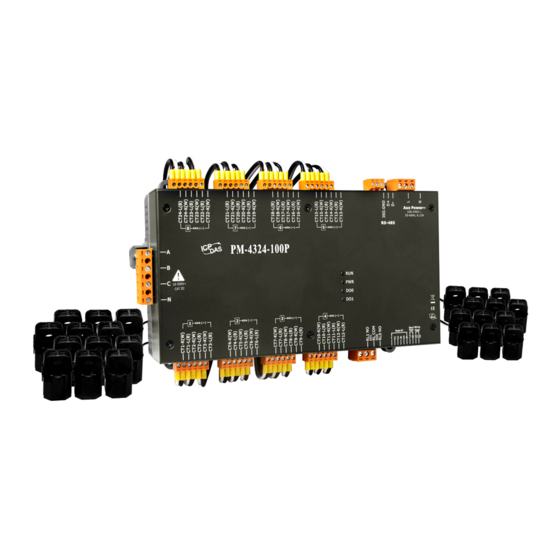
Smart power meter
Hide thumbs
Also See for PM-4324 Series:
- Quick start manual (9 pages) ,
- User manual (83 pages) ,
- User manual (88 pages)

Related Manuals for ICP DAS USA PM-4324 Series


Summary of Contents for ICP DAS USA PM-4324 Series
- Page 1 PM-4324 User’s Manual v1.02 Last Revised: May. 2017 Page: 1 E-mail: service@icpdas.com Copyright © ICP DAS Co., Ltd. All Rights Reserved. www.icpdas.com...
-
Page 2: Table Of Contents
Chapter 1 Introduction ........4 Chapter 4 Wiring Diagrams ......14 1.1. PM-4324 introduction ..4 Connection ...... 14 1.2. Caution ......5 Wiring ......16 1.2.1. Danger ......5 Chapter 5 Relay output & LED Indicator ..18 1.3. Warning ...... - Page 3 7.2.1.3 Abort SDO Transfer Protocol 7.2.4 Special Functions for ........47 PM-4324-CPS ....57 7.2.2 PDO Introduction .... 50 7.2.4.1 Power Meter Data Table .. 57 7.2.2.1 PDO COB-ID Parameters 50 7.2.5 Object Dictionary of PM-4324-CPS ....59 7.2.2.2 Transmission Type..51 7.2.5.1 Communication Profile Area 7.2.2.3...
-
Page 4: Chapter 1 Introduction
The products offer a rich feature set combined with easy-to-integrate communications. With its high accuracy (<0.5%, PF=1), the PM-4324 series products can be applied both on low voltage primary side and/or medium/high voltage secondary side and enable the users to obtain in real time the reliable and accurate energy consumption readings from the monitored equipments while in operation. -
Page 5: Caution
1.2. Caution 1.2.1. Danger The meter contains hazardous voltages, and should never be disassembled. Failing to follow this practice will result in serious injury or death. Any work on or near energized meters, meter sockets, or other metering equipment could induce a danger of electrical shock. -
Page 6: Limitation Of Warranty
1.4.1. Limitation of Warranty This warranty does not apply to defects resulting from unauthorized modification, misuse, or use for reason other than electrical power monitoring. The supplied meter is not a user-serviceable product. PM-4324 User’s Manual v1.02 Last Revised: May. 2017 Page: 6 ... -
Page 7: Chapter 2 Specifications
Chapter 2 Specifications 2.1 Specifications Model PM-4324 PM-4324-MTCP PM-4324-CPS AC Power Measurement Wiring 1P2W-1CT, 1P3W-2CT, 3P3W-2CT, 3P3W-3CT and 3P4W-3CT Measurement Voltage 10 ~ 500 V (CAT III) CT Φ10 mm (60 A); CTΦ16 mm (100 A); CTΦ24 mm (200 A); Measurement Current CTΦ36m (300 A);... - Page 8 Aux Power Input Range +100 ~ +240 VAC +100 ~ +240 VAC +100 ~ +240 VAC Power Consumption Dimensions (W x L x H) 237 mm x 52 mm x 134 mm Environment Operating Temperature -20 ~ +70 °C Storage Temperature -25 ~ +80 °C Field Wiring Terminal Markings: 3.81mm (For Measurement Current and Communication): Use Copper Conductors Only,...
-
Page 9: Naming Rules
2.2 Naming Rules PM-4324 User’s Manual v1.02 Last Revised: May. 2017 Page: 9 E-mail: service@icpdas.com Copyright © ICP DAS Co., Ltd. All Rights Reserved. www.icpdas.com... -
Page 10: Chapter 3 Installation
Chapter 3 Installation 3.1 Inspection The instrument is no longer safe when, a) Shows clear signs of damage b) Does not work c) Long storage under extreme conditions d) Damage during shipment 3.2 Safety Please use the soft dry clothes to clean the instrument. Please do not use any chemical or detergent or volatile solvents to clean the instrument, in order to avoid any possibility of the cover damage. - Page 11 Please re-confirm the measure position. PM-4324 series can be installed as rail mounting mode or embedded, no need to drill a hole or screw to fix it (rail mounting width can up to the length of 35 mm). ...
-
Page 12: Mounting And Dismounting 7.2.1.2
3.2.2 Mounting and Dismounting Mounting Assembly: Place the PM-4324 on the DIN-Rail. Push the front of the PM-4324 toward the mounting surface until it audibly snaps into place. Dismantling: Pull out the latch and then remove the PM-4324 from the DIN-Rail ... -
Page 13: Ct's Installation Steps
3.2.3 CT’s installation steps At the bottom of the CT, there is a “K→L” mark. Open the CT clip. Make sure the power current Installation steps finished. direction follow the “K→L” mark on the CT and then close the CT clip. PM-4324 User’s Manual v1.02 Last Revised: May. -
Page 14: Chapter 4 Wiring Diagrams
Chapter 4 Wiring Diagrams 4.1 Connection Please firstly check the current input terminal, and then in white black, white black, white black wire sequences (CT1-K, CT1-L, CT2-K, CT2-L, CT3-K, CT3-L). Then connect the CT’s, and close the CT clip. Make sure the arrow direction sign on CT’s follows current flow direction(K→L)... - Page 15 The external CT’s are fragile, please handle with care. The current input of PM-4324 series is in mA range. Only the ex-factory attached CT’s can be used. The other CT’s, for example, from panel will damage the instrument due to its large current (around When more than one smart meter (PM-4324 series) are installed, please do not disconnect the CT with its original meter and mix use with each other.
-
Page 16: Wiring
4.2 Wiring 1P2W-1CT (PM-4324) 1P3W-2CT (PM-4324) 3P3W-2CT (PM-4324) 3P3W-3CT (PM-4324) PM-4324 User’s Manual v1.02 Last Revised: May. 2017 Page: 16 E-mail: service@icpdas.com Copyright © ICP DAS Co., Ltd. All Rights Reserved. www.icpdas.com... - Page 17 DIP switch: Wiring mode SW 9 SW 10 3P3W-3CT 3P4W-3CT (PM-4324) DIP switch: Wiring mode SW 9 SW 10 3P4W-3CT PM-4324 User’s Manual v1.02 Last Revised: May. 2017 Page: 17 E-mail: service@icpdas.com Copyright © ICP DAS Co., Ltd. All Rights Reserved. www.icpdas.com...
-
Page 18: Chapter 5 Relay Output & Led Indicator
Chapter 5 Relay output & LED Indicator 5.1 Relay Relay type Power Relay, Form A (SPST N.O.) Operating Voltage Range 250 VAC/30 VDC Max. Load Current 5 A at 25 °C Operate Time 6 ms Release Time 3 ms 5.2 LED Indicator The PM-4324 has 4 LED to indicate the unit power status, RS-485 communication, and power data calculation. -
Page 19: Chapter 6 Modbus-Rtu Communication
Chapter 6 Modbus-RTU communication 6.1 RS-485 setting Default setting for RS-485: 19200, n, 8, 1 DIP switch (SW1-SW6) is used for Modbus address setting, default is 1, i.e. all OFF For example: Modbus address is 10,find the table of DIP switch 1-6 is ON, OFF, OFF, ON, OFF, OFF 6.1.1 SW1-SW6 setting Setting Modbus-RTU address for communication (1-64) - Page 20 PM-4324 User’s Manual v1.02 Last Revised: May. 2017 Page: 20 E-mail: service@icpdas.com Copyright © ICP DAS Co., Ltd. All Rights Reserved. www.icpdas.com...
- Page 21 Add the Bias Resistor on RS-485 Network for stable signal The RS-485 master is required to provide the bias for PM-4324 series. Otherwise, the tM-SG4 or SG-785 should be added to provide the bias. All ICP DAS controllers and converters provide the bias.
-
Page 22: Modbus-Rtu Setting
6.2 Modbus-RTU setting 6.2.1 Specifications Protocol Modbus-RTU Transmission Bits per Byte: Specifications 1 start bit 8 data bits, least significant bit sent first None Parity 1 stop bits Error Check: Cyclical Redundancy Check (CRC) Baud Rate 9600, 19200 (Default), 38400, 115200 Modbus slave address 1-64 (Default = 1) ... - Page 23 IEEE 754 Format Definition of the floating format of the Bits Data Hi Word, Data Hi Word, Data Lo Word, Data Lo Word, Hi Byte Lo Byte Hi Byte Lo Byte SEEE EEEE EMMM MMMM MMMM MMMM MMMM MMMM E -127 Value = (- 1) x (1.M) x 2 0 <...
-
Page 24: Modbus Register
6.2.2 Modbus Register Modbus Module #1 – Coil: Relay Value Modbus Register Data Default Parameter name Range Comment Modicom value Type Format 0 = OFF DO 0 04097 0x1000 Word Byte 1 = ON 0 = OFF DO 1 04098 0x1001 Word... - Page 25 1: 1P2W 2: 1P3W Only work when Wiring Mode 44107 0x100A Word UInt 3: 3P3W2CT SW9-SW10 is all 4: 3P3W3CT 5: 3P4W3CT 1: submeter1 2: submeter2 3: submeter3 4: submeter4 Set Energy to Zero 44108 0x100B Word UInt 5: submeter5 Only Write 6: submeter6 7: submeter7...
- Page 26 0: Disable Harmonic Phase 1: Phase A For Submeter3 44116 0x1013 Word UInt Select 3 2: Phase B 3: Phase C 0: Disable Harmonic Phase 1: Phase A 44117 0x1014 Word UInt For Submeter4 Select 4 2: Phase B 3: Phase C 0: Disable Harmonic Phase 1: Phase A...
- Page 27 Modbus Module #3 - Input Register : System Information Modbus Register Data Default Parameter name Range Units Comment Modicom Type value Format 9: 1P2W 10: 1P3W 11: 3P3W2CT 12: 3P3W3CT (HW):set 13: 3P4W3CT wiring by 14: 3P3W2CT Wiring Type 30513 0x0200 Word...
- Page 28 Modbus Module #4 - Input Register :Power value (Float) for Submeter1 Modbus Register Parameter Data Type Range Units Comment name Modicom Format 0x1100- 0x1101 34353-34354 DWord Float Volt 34355- 34356 0x1102- 0x1103 DWord Float 34357- 34358 0x1104- 0x1105 DWord Float kW_a 34359- 34360...
- Page 29 34417-34418 0x1140-0x1141 PF_tot DWord Float 34419-34420 0x1142-0x1143 kWh_tot DWord Float 34421-34422 0x1144-0x1145 kvarh_tot DWord Float 34423-34424 0x1146-0x1147 kVAh_tot DWord Float 34425-34426 0x1148-0x1149 Freq_a DWord Float 45~65 For CT_1 34427-34428 0x114A-0x114B Freq_b DWord Float 45~65 For CT_2 34429-34430 0x114C-0x114D Freq_c DWord Float 45~65 For CT_3...
- Page 30 34651-34652 0x122A-0x122B kvar_c DWord Float kvar 34653-34654 0x122C-0x122D kVA_c DWord Float 34655-34656 0x122E-0x122F PF_c DWord Float 34657-34658 0x1230-0x1231 kWh_c DWord Float 34659-34660 0x1232-0x1233 kvarh_c DWord Float 34661-34662 0x1234-0x1235 kVAh_c DWord Float 34663-34664 0x1236-0x1237 V_avg DWord Float Volt 34665-34666 0x1238-0x1239 I_avg DWord Float 34667-34668...
- Page 31 34885- 34886 0x1314- 0x1315 DWord Float 34887- 34888 0x1316- 0x1317 kW_b DWord Float 34889- 34890 0x1318- 0x1319 kvar_b DWord Float kvar 34891- 34892 0x131A- 0x131B kVA_b DWord Float 34893- 34894 0x131C- 0x131D PF_b DWord Float 34895- 34896 0x131E- 0x131F kWh_b DWord Float 34897- 34898...
- Page 32 Modbus Module #7 - Input Register :Power value (Float) for Submeter4 Modbus Register Parameter Data Type Range Units Comment name Modicom Format 35121-35122 0x1400- 0x1401 DWord Float Volt 0x1402- 0x1403 35123-35124 DWord Float 35125-35126 0x1404- 0x1405 kW_a DWord Float 0x1406- 0x1407 35127-35128 kvar_a...
- Page 33 35185-35186 0x1440-0x1441 PF_tot DWord Float 35187-35188 0x1442-0x1443 kWh_tot DWord Float 35189-35190 0x1444-0x1445 kvarh_tot DWord Float 35191-35192 0x1446-0x1447 kVAh_tot DWord Float 35193-35194 0x1448-0x1449 Freq_a DWord Float 45~65 For CT_10 35195-35196 0x144A-0x144B Freq_b DWord Float 45~65 For CT_11 35197-35198 0x144C-0x144D Freq_c DWord Float 45~65 For CT_12...
- Page 34 35419-35420 0x152A-0x152B kvar_c DWord Float kvar 35421-35422 0x152C-0x152D kVA_c DWord Float 35423-35424 0x152E-0x152F PF_c DWord Float 35425-35426 0x1530-0x1531 kWh_c DWord Float 35427-35428 0x1532-0x1533 kvarh_c DWord Float 35429-35430 0x1534-0x1535 kVAh_c DWord Float 35431-35432 0x1536-0x1537 V_avg DWord Float Volt 35433-35434 0x1538-0x1539 I_avg DWord Float 35435-35436...
- Page 35 0x160C- 0x160D 35645-35646 kWh_a DWord Float 35647-35648 0x160E- 0x160F kvarh_a DWord Float 0x1610- 0x1611 35649-35650 kVAh_a DWord Float 35651-35652 0x1612- 0x1613 DWord Float Volt 35653-35654 0x1614- 0x1615 DWord Float 35655-35656 0x1616- 0x1617 kW_b DWord Float 0x1618- 0x1619 35657-35658 kvar_b DWord Float kvar 35659-35660...
- Page 36 Modbus Module #10 - Input Register :Power value (Float) for Submeter7 Modbus Register Parameter Data Type Range Units Comment name Modicom Format 35889-35890 0x1700- 0x1701 DWord Float Volt 35891-35892 0x1702- 0x1703 DWord Float 35893-35894 0x1704- 0x1705 kW_a DWord Float 35895-35896 0x1706- 0x1707 DWord...
- Page 37 35951-35952 0x173E-0x173F kVA_tot DWord Float 35953-35954 0x1740-0x1741 PF_tot DWord Float 35955-35956 0x1742-0x1743 kWh_tot DWord Float 35957-35958 0x1744-0x1745 kvarh_tot DWord Float 35959-35960 0x1746-0x1747 kVAh_tot DWord Float 35961-35962 0x1748-0x1749 Freq_a DWord Float 45~65 For CT_19 35963-35964 0x174A-0x174B Freq_b DWord Float 45~65 For CT_20 35965-35966 0x174C-0x174D Freq_c...
- Page 38 36185-36186 0x1828-0x1829 kW_c DWord Float 36187-36188 0x182A-0x182B kvar_c DWord Float kvar 36189-36190 0x182C-0x182D kVA_c DWord Float 36191-36192 0x182E-0x182F PF_c DWord Float 36193-36194 0x1830-0x1831 kWh_c DWord Float 36195-36196 0x1832-0x1833 kvarh_c DWord Float 36197-36198 0x1834-0x1835 kVAh_c DWord Float 36199-36200 0x1836-0x1837 V_avg DWord Float Volt 36201-36202...
-
Page 39: Chapter 7 Canopen Communication
Chapter 7 CANopen communication 7.1 CANopen setting Default setting for CANopen: Baud rate:125 K b.p.s. , Node ID:1 DIP switch (SW1-SW6) is used for Node ID setting, default is 1, i.e. all OFF For example: Node ID is 10,find the table of DIP switch 1-6 is ON, OFF, OFF, ON, OFF, OFF SW1-SW6 setting ... - Page 40 PM-4324 User’s Manual v1.02 Last Revised: May. 2017 Page: 40 E-mail: service@icpdas.com Copyright © ICP DAS Co., Ltd. All Rights Reserved. www.icpdas.com...
-
Page 41: Canopen Protocol
SW7-SW8 setting PM-4324-CPS:For CANopen Baud Rate Setting Baud Rate SW 7 125 K bps(Default) 250 K bps 500 K bps 1M bps SW9-SW10 setting PM-4324-CPS:Select the different wiring mode (Please select the Software setting, if 1P2W-1CT or 1P3W-2CT is used) Wiring SW 9 SW 10... -
Page 42: Sdo Introduction
7.2.1 SDO Introduction 7.2.1.1 Upload SDO Protocol Initiate SDO Upload Protocol Before transferring the SDO segments, the client and server need to communicate with each other by using the initiate SDO upload protocol. Via the initiate SDO upload protocol, the SDO client will inform the SDO server what object the SDO client wants to request. - Page 43 0: normal transfer 1: expedited transfer If the e=1, it means that the data of the object are equal or less than 4 bytes, and only initiate SDO upload protocol is needed. If e=0, the upload SDO segment protocol is necessary. s: size indicator 0: Data set size is not indicated.
-
Page 44: Download Sdo Protocol
ccs: client command specified 3: upload segment request scs: server command specified 0: upload segment response t: toggle bit. This bit must alternate for each subsequence segment that is uploaded. The first segment will have the toggle bit set to 0. The toggle bit will be equal for the request and response message. - Page 45 ccs: client command specified 1: initiate download request scs: server command specified 3: initiate download response n: Only valid if e = 1 and s = 1, otherwise 0. If valid, it indicates the number of bytes in d that do not contain data. Bytes [8-n, 7] do not contain segment data.
- Page 46 Download Segment Protocol ccs: client command specified 0: download segment request scs: server command specified 1: download segment response seg-data: It is at most 7 bytes of segment data to be downloaded. The encoding depends on the type of the data referenced by index and sub-index. n: It indicates the number of bytes in seg-data that do not contain segment data.
- Page 47 7.2.1.3 Abort SDO Transfer Protocol In some conditions, the SDO client or SDO server will terminate the SDO transmission. For example, the value of entries that users want to modify does not exist or is read-only, even users wouldn’t continue the uncompleted SDO protocol under some special situations.
- Page 48 Abort Code Description 0503 0000h Toggle bit not alternated. 0504 0000h SDO protocol timed out. 0504 0001h Client/server command specified not valid or unknown. 0504 0002h Invalid block size (block mode only). 0504 0003h Invalid sequence number (block mode only). 0504 0004h CRC error (block mode only).
- Page 49 generation fails because of an file error). PM-4324 User’s Manual v1.02 Last Revised: May. 2017 Page: 49 E-mail: service@icpdas.com Copyright © ICP DAS Co., Ltd. All Rights Reserved. www.icpdas.com...
- Page 50 7.2.2 PDO Introduction 7.2.2.1 PDO COB-ID Parameters Before the real-time data are transmitted by the PDO, it is necessary to check the COB-ID parameter of this PDO in the PDO communication objects. This parameter setting controls the COB-ID of the PDO communication, which is in 32 bits, and each bit with its meaning is given in the table follow.
- Page 51 Note: 1. Users can also define the PDO COB-ID by themselves. Actually, all COB-ID can be defined by users except the reserved COB-ID described in the table of the section 3.1. It is important to avoid the conflict with the defined COB-ID used in the same node.
- Page 52 The PDO, including the DI value, will be sent when the DI value is changed. And both transmission types will directly trigger an update of the mapped data when receiving the RxPDO. 7.2.2.3 PDO Communication Rule The PDO related objects are indicated from index 0x1400 to 0x1BFF. For the PM-4324-CPS, RxPDO communication objects are not used.
- Page 53 COB-ID: the default PDO COB-ID, or the PDO COB-ID defined by users L: the data length about how many bytes the PDO message has PDO-msg: the real-time data or the data which can be mapped into the PDO mapping objects PM-4324 User’s Manual v1.02 Last Revised: May.
- Page 54 7.2.3 NMT Introduction 7.2.3.1 Module Control Protocol The NMT communication set can be applied for changing the NMT slave status. The following figure shows how to change the different NMT statuses for the PM-4324-CPS. Start Remote Node Protocol cs: NMT command specified 1: start Node ID: the node ID of the NMT slave device Stop Remote Node Protocol...
- Page 55 Enter Pre-Operational Protocol cs: NMT command specified 128: enter PRE-OPERATIONAL Node ID: the node ID of the NMT slave device Reset Node Protocol cs : NMT command specified 129: Reset_Node Node ID : the node ID of the NMT slave device PM-4324 User’s Manual v1.02 Last Revised: May.
- Page 56 Reset Communication Protocol cs: NMT command specified 130: Reset_Communication Node ID: the node ID of the NMT slave device 7.2.3.2 Error Control Protocol Error Control Protocol is a kind of the solution to check whether the CANopen device is still alive or not. And its related objects include 0x100C and 0x100D. The 0x100C is the guard time, and the 0x100D is the life time factor.
- Page 57 s: the state of the NMT Slave 4: STOPPED 5: OPERATIONAL 127: PRE_OPERATIONAL 7.2.4 Special Functions for PM-4324-CPS 7.2.4.1 Power Meter Data Table The PM-4324-CPS Manufacturer in the Specific Profile Area defines some entries, which are used for the power meter data. The objects with index 0x3200~0x3203 will map to the PDOs as below table.
- Page 58 No.(PDO) COB-ID Data D0~D3 D4~D7 Length kW(Kw_a)_CT16 kWh_a_CT16 kW(Kw_b)_CT17 kWh_b_CT17 kW(Kw_c)_CT18 kWh_c_CT18 kW(Kw_tot)_M6 kWh_tot_M6 kW(Kw_a)_CT19 kWh_a_CT19 kW(Kw_b)_CT20 kWh_b_CT20 kW(Kw_c)_CT21 kWh_c_CT21 kW(Kw_tot)_M7 kWh_tot_M7 kW(Kw_a)_CT22 kWh_a_CT22 kW(Kw_b)_CT23 kWh_b_CT23 kW(Kw_c)_CT24 kWh_c_CT24 kW(Kw_tot)_M8 kWh_tot_M8 Volt(V_a)_CT1 Amp(I_a)_CT1 Volt(V_b)_CT2 Amp(I_b)_CT2 Volt(V_c)_CT3 Amp(I_c)_CT3 Volt(V_avg)_M1 Amp(I_avg)_M2 Volt(V_a)_CT4 Amp(I_a)_CT4 Volt(V_b)_CT5 Amp(I_b)_CT5 Volt(V_c)_CT6...
- Page 59 7.2.5 Object Dictionary of PM-4324-CPS 7.2.5.1 Communication Profile Area The following tables are regarding each entry of the communication profile area is defined in PM-4324-CPS. For the convenient purpose, all communication entries are divided into several tables. They are “General Communication Entries”, “TxPDO Communication Entries”, and “TxPDO Mapping Communication Entries”.
- Page 60 SDO Communication Entries Sidx Description Type Attr Default 1200h 0h largest sub-index supported UNSIGNED 8 RO 2 for “server SDO parameter” COB-ID form client to server UNSIGNED 32 RO 600h+Node-ID (RxSDO) COB-ID form server to clien UNSIGNED 32 RO 580h+Node-ID t(TxSDO) TxPDO Communication Entries Sidx Description...
- Page 61 inhibit time UNSIGNED 16 Reversed … … … event timer UNSIGNED 16 1804h largest sub-index supported UNSIGNED 8 for “receive PDO parameter” COB-ID used by PDO (Tx) UNSIGNED 32 80000000h transmission type UNSIGNED 8 inhibit time UNSIGNED 16 Reversed … …...
- Page 62 1A05h largest sub-index UNSIGNED 8 read Kw_b CT5 INTEGER 32 3200 0620h read kWh_b CT5 INTEGER 32 3201 0620h 1A06h largest sub-index” UNSIGNED 8 read Kw_c CT6 INTEGER 32 3200 0720h read kWh_c CT6 INTEGER 32 3201 0720h 1A07h largest sub-index UNSIGNED 8 read Kw_tot Meter2 INTEGER 32...
- Page 63 1A11h largest sub-index UNSIGNED 8 read Kw_b CT14 INTEGER 32 3200 1220h read kWh_b CT14 INTEGER 32 3201 1220h 1A12h largest sub-index UNSIGNED 8 read Kw_c CT15 INTEGER 32 3200 1320h read kWh_c CT15 INTEGER 32 3201 1320h 1A13h largest sub-index UNSIGNED 8 read Kw_tot Meter5 INTEGER 32...
- Page 64 1A1Ch 0 largest sub-index UNSIGNED 8 read Kw_a CT22 INTEGER 32 3200 1D20h read kWh_a CT22 INTEGER 32 3201 1D20h 1A1Dh 0 largest sub-index UNSIGNED 8 read Kw_b CT23 INTEGER 32 3200 1E20h read kWh_b CT23 INTEGER 32 3201 1E20h 1A1Eh 0 largest sub-index UNSIGNED 8...
- Page 65 1A27h largest sub-index UNSIGNED 8 read V_avg Meter2 INTEGER 32 3202 0820h read I_avg Meter2 INTEGER 32 3203 0820h PM-4324 User’s Manual v1.02 Last Revised: May. 2017 Page: 65 E-mail: service@icpdas.com Copyright © ICP DAS Co., Ltd. All Rights Reserved. www.icpdas.com...
- Page 66 7.2.5.2 Manufacturer Specific Profile Area In the following table, there is information about some special functions for the PM-4324-CPS. The index from 0x3200 to 0x3209 records the power meter measurement parameters. The number of these entries will be automatically updated when the PM-4324-CPS boot up.
- Page 67 “Volt” Volt(V_a) (Meter 1) INTEGER32 Volt(V_b) (Meter 1) INTEGER32 Volt(V_c) (Meter 1) INTEGER32 Volt(V_avg) (Meter 1) INTEGER32 … … … … Volt(V_a) (Meter 8) INTEGER32 Volt(V_b) (Meter 8) INTEGER32 Volt(V_c) (Meter 8) INTEGER32 Volt(V_avg) (Meter 8) INTEGER32 3203h largest sub-index supported for UNSIGNED 8 “Amp”...
- Page 68 kVA(Kva_c) (Meter 1) INTEGER32 kVA(Kva_tot) (Meter 1) INTEGER32 … … … … kVA(Kva_a) (Meter 8) INTEGER32 kVA(Kva_b) (Meter 8) INTEGER32 kVA(Kva_c) (Meter 8) INTEGER32 kVA(Kva_tot) (Meter 8) INTEGER32 3206h largest sub-index supported for UNSIGNED 8 “PF” PF_a (Meter 1) INTEGER32 PF_b (Meter 1) INTEGER32 PF_c (Meter 1)
- Page 69 kvarh_a (Meter 8) INTEGER32 kvarh_b (Meter 8) INTEGER32 kvarh_c (Meter 8) INTEGER32 kvarh_tot (Meter 8) INTEGER32 3209h largest sub-index supported for UNSIGNED 8 “Frequency” Freq_a (Meter 1) INTEGER32 Freq _b (Meter 1) INTEGER32 Freq _c (Meter 1) INTEGER32 Freq _avg (Meter 1) INTEGER32 …...
- Page 70 3: 3P3W2CT 4: 3P3W3CT 5: 3P4W3CT Energy Absolute Accumulated UNSIGNED 16 RW Mode 0: Enable 1: Disable Display Voltage UNSIGNED 16 RW 0: Automatic 1: Show as Vln 2: Show as Vll 320Ch 0 largest sub-index supported for UNSIGNED 8 object H Phase Select1 UNSIGNED 16 RW...
- Page 71 Application Object The users can write the object the value 65766173h to object with index 1010h and subindex 1 to save the application setting, or write the value 64616F6Ch to object with index 1011h and subindex 1 and reboot the module to load the factory default. PM-4324 User’s Manual v1.02 Last Revised: May.
- Page 72 Q1. Can we use the other 5A CT’s (like 600/5) to directly connect to the input current terminals of PM-4324 series? No, because the input current is only mA size on PM-4324 series,definitely not to directly use other 5A CT’s to connect and apply (like100/5…) ,It could causes the fetal damages.
- Page 73 (4) Confirm the RS-485 connection, make sure the D+/D- is right. (5) Confirm the RS-485 master have to provide the bias for PM-4324 series. Otherwise, the tM-SG4 or SG-785 should be added to provide the bias. All ICP DAS controllers and converters provide the bias.
- Page 74 The CT of PM-4324 maximum range is 400A. If the target is more than 400A, we suggest the solution as follow. For example the target is to measure maximum 800A current. We can measure big CT output and set a CT Ratio. Note: A.
- Page 75 Q11. Can I use CT's that I currently own with PM-4324 Power Meter? You can use CT's that you currently own with PM-4324P (without CTs) Power Meter. The CT inputs of the PM-4324P can handle a maximum of 333mV of AC current. PM-4324P's current ratio is always full scale to 5A.
- Page 76 example, on a 380 volt wye system, line to line voltage is 380 volts and line to ground voltage is 380/1.73 = 220 volts Q13. How about the harmonic (THD) analysis capability? PM-4324 User’s Manual v1.02 Last Revised: May. 2017 Page: 76 ...
- Page 77 The number of harmonics N that can be analyzed within the 2.8 kHz pass band is the whole number of 2800/f. The absolute maximum number of harmonics accepted by the Energy Metering IC is 63. N = [2800/f], N ≤ 63 Q14.
- Page 78 The voltage [V_x] register in Modbus register table can be used to show line-to-ground voltage or line-to-line voltage value by setting [Display Voltage] register value. According to different wiring types, it is required to set different [Display Voltage] value. If the voltage is not displayed as expected value, please refer to the table below and check if the setting value is set accurately.
Need help?
Do you have a question about the PM-4324 Series and is the answer not in the manual?
Questions and answers