Table of Contents
Advertisement
Household Unit Technical Service Manual
Technical Service Manual
SEER13:
HW(R)18-D/HNF(R)18-D HW(R)24-D/HNF(R)24-D
HW(R)30-D/HNF(R)30-D HW(R)36-D/HNF(R)36-D
HW(R)42-D/HNF(R)42-D HW(R)48-D/HNF(R)48-D
SEER10~12:
Household Unit
HW(R)60-D/HNF(R)60-D
HW(R)18M-D HW(R)24M-D
HW(R)30M-D HW(R)36M-D
HW(R)42M-D HW(R)48M-D
HW(R)60M-D
1
Advertisement
Table of Contents

Related Manuals for Gree SEER13 Series


Summary of Contents for Gree SEER13 Series
- Page 1 Household Unit Technical Service Manual Household Unit Technical Service Manual SEER13: HW(R)18-D/HNF(R)18-D HW(R)24-D/HNF(R)24-D HW(R)30-D/HNF(R)30-D HW(R)36-D/HNF(R)36-D HW(R)42-D/HNF(R)42-D HW(R)48-D/HNF(R)48-D HW(R)60-D/HNF(R)60-D SEER10~12: HW(R)18M-D HW(R)24M-D HW(R)30M-D HW(R)36M-D HW(R)42M-D HW(R)48M-D HW(R)60M-D...
-
Page 2: Table Of Contents
Household Unit Technical Service Manual Contents Chapter 1 General Information 1.1 Model Identification 1.2 Product Features 1.3 External View 1.3.1 External View of Outdoor Unit 1.3.2 External View of Indoor Unit 1.4 Dimensional Size and Installation Space 1.4.1 Overall Dimension 1.4.1.1 Overall Dimension of Outdoor Unit 1.4.1.2 Overall Dimension of Indoor Unit 1.4.2 Installation Requirements... - Page 3 Household Unit Technical Service Manual 3.2.1 Fault Analysis Flow 3.2.2 Fault Analysis Chapter 4 Care and Maintenance 4.1 Explosion View and Parts List for Model SEER13 4.1.1 Explosion View and Parts List for HW(R)18-D & HW(R)24-D 4.1.2 Explosion View and Parts List for HW(R)30-D 4.1.3 Explosion View and Parts List for HW(R)36-D &...
-
Page 4: Chapter 1 General Information
Household Unit Technical Service Manual Chapter 1 General Information 1.1 Model Identification Power Ratings Design S/N Refrigerant Special Functions Cooling Capacity Cooling Mode Functions Indoor Unit U.S Household Central Air Conditioning Unit Model Definition: Unit Indoor Unit Function Cooling Mode Cooling Capacity Definition Cooling-only - None... - Page 5 Household Unit Technical Service Manual enhance indoor air quality.
-
Page 6: External View
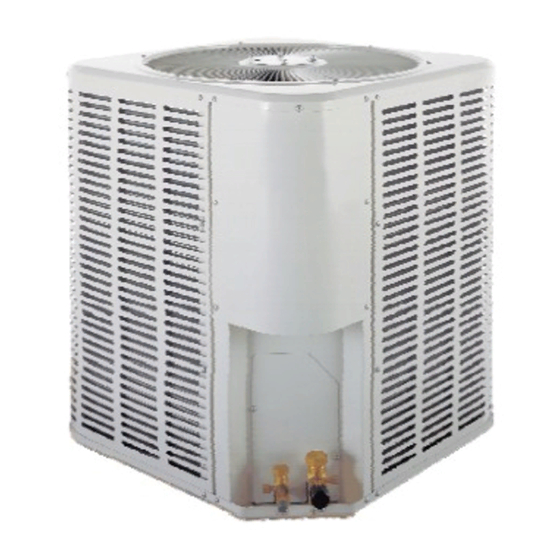
Household Unit Technical Service Manual 1.3 External View 1.3.1 External View of Outdoor Unit 1.3.2 External View of Indoor Unit... -
Page 7: Dimensional Size And Installation Space
Household Unit Technical Service Manual 1.4 Dimensional Size and Installation Space 1.4.1 Overall Dimension 1.4.1.1 Overall Dimension of Outdoor Unit 出风 Outlet 底部视图 Bottom View 进风 Air Intake 进风 Air Intake 进风 Air Intake 接气管 To gas pipe To liquid pipe 接液管... -
Page 8: Overall Dimension Of Indoor Unit
Household Unit Technical Service Manual 1.4.1.2 Overall Dimension of Indoor Unit Unit: mm HNF18-D HNF36-D HNF48-D Model HNF24-D HNF42-D HNF60-D HNF30-D 1040 1180 1180 1.4.2 Installation Requirements 1.4.2.1 Installation Space of Outdoor Unit Floor 楼面 Ground 地面... -
Page 9: Installation Of Indoor Unit
Household Unit Technical Service Manual 1.4.2.2 Installation of Indoor Unit For HNF series U.S household unit, three installations are available at your option: Downward Blow Installation Upward Blow Installation Level Blow Installation 1.4.3 Handling of Outdoor Unit To handle the unit, be sure to use two ropes of enough length to lift from four directions. To avoid deviation from the center of unit, the angle between the lifting ropes must be less than 40 . -
Page 10: Selection Of Installation Location
Household Unit Technical Service Manual 1.4.5 Selection of Installation Location ◇ The compressor condensing unit must be installed on the stable and firm supporting plane outside the construction. ◇ The compressor condensing unit shall be installed as close as possible to the indoor unit, thus to decrease the length and bends of the cooling pipe. - Page 11 Household Unit Technical Service Manual compressor. This cycle is so repeated and the warm air is continuously blown into the air conditioning area under the force of the fan.
- Page 12 Household Unit Technical Service Manual a) Schematic Diagram for Cooling-only Unit 干燥过滤器 Drying filter Liquid 分液器 separator Expansion valve assy. 膨胀阀组件 Liquid pipe manhole 液管维修阀 Outdoor side 室外侧 轴流风机 Axial flow fan heat 换热器 exchanger Gas pipe 汽管维修阀 manhole Indoor side 室内侧...
-
Page 13: Performance Specifications
Household Unit Technical Service Manual 1.8 Performance Specifications 1.8.1 SEER13 Specifications and Technical Data Model HW(R)18-D HW(R)24-D HW(R)30-D HW(R)36-D HW(R)42-D HW(R)48-D HW(R)60-D Rated (BTU/h) 18000 24000 30000 36000 42000 48000 60000 cooling capacity 10.5 12.3 14.1 17.6 Rated Heat Pump heating Type 10.6... -
Page 14: Seer10~12 Specifications And Technical Data
Household Unit Technical Service Manual Notes: ① This unit is designed in accordance with GB/T18836-2002. ② The technical data for the complete unit are measured under American air conditioning conditions. The data are subject to change with the modification. Please refer to the ratings on the nameplate. - Page 15 Household Unit Technical Service Manual Notes: ① This unit is designed in accordance with GB/T18836-2002. ②The technical data for the complete unit are measured under American air conditioning conditions. The data are subject to change with the modification. Please refer to the ratings on the nameplate.
-
Page 16: Chapter 2 Electrical And Control
Household Unit Technical Service Manual Chapter 2 Electrical and Control 2.1 Outdoor Side Wiring Diagram External Wiring Diagram for Cooling-only HW Series External Wiring Diagram for Heat Pump HWR Series... -
Page 17: Indoor Side Wiring Diagram
Household Unit Technical Service Manual 2.2 Indoor Side Wiring Diagram... -
Page 18: Chapter 3 Run Test And Fault Analysis
Household Unit Technical Service Manual Chapter 3 Run Test and Fault Analysis 3.1 Checklist of Operating Conditions Test Item Remarks □ □ If the capacity of outdoor unit is compatible to that of indoor unit Others: □ □ If the pipes between indoor and outdoor unit are connected correctly. Others: □... -
Page 19: Fault Analysis
Household Unit Technical Service Manual 3.2 Fault Analysis 3.2.1 Fault Analysis Flow The air conditioner cannot 空调机不能起动 be started 断路器跳闸(或 当将断路设定在" 开" The circuit breaker is Measure insulation Tripping occurs immediately 对接地,测绝缘电阻 tripped (or the fuse is resistance to the ground. after the circuit breaker is set to 保险丝熔断)... -
Page 20: Fault Analysis
Household Unit Technical Service Manual 3.2.2 Fault Analysis Fault Possible Cause How to Eliminate Fault Possible Cause How to Eliminate Resume the power Power failure 4-way valve failure Replace the 4-way valve supply The thermal Replace the thermal Eliminate short circuit; expansion valve is Short circuit expansion valve. -
Page 21: Chapter 4 Care And Maintenance
Household Unit Technical Service Manual Chapter 4 Care and Maintenance 4.1 Explosion View and Parts List for Model SEER13 4.1.1 Explosion View and Parts List for HW(R)18-D & HW(R)24-D 4.1.1.1 Explosion View Fig. 1... - Page 22 Household Unit Technical Service Manual 4.1.1.2 Parts List Model: HW(R)18-D Finished Product Code: EM115W0390 Description Part Code Motor fixing nut 70318204 Cover plate 01258248 Motor SW120C 15702101 Cable-cross pipe 05012140 Fixing block (cable-cross pipe) 01722121 10358203 Compressor and its accessories 00100234 2K21S236A6E Chassis assy.
-
Page 23: Explosion View And Parts List For Hw(R)30-D
Household Unit Technical Service Manual Capacitor CBB65 45uF/440V(450V) 33000012 Connection plate assy. (condenser) 01388214 Flow diverter 03413014 Condenser assy. 01152102 Side plate 01308226 Table 2 HW(R)24-D Parts List 4.1.2 Explosion View and Parts List for HW(R)30-D 4.1.2.1 Explosion View Fig. 2 4.1.2.2 Parts List Model: HW(R)30-D Finished Product Code: CM115W223... -
Page 24: Explosion View And Parts List For Hw(R)36-D & Hw(R)42-D
Household Unit Technical Service Manual AC Contactor CJX9B-25S/D-C1 44010250 Terminal board (3-bit) 42011242 Terminal board (2-bit) 420111451 Capacitor CBB65 40uF/450V 33000022 Connection plate assy. (Condenser) 33000022 Liquid separator 07220011 Condenser assy. 01152103 Side plate 01318213 Table 3 HW(R)30-D Parts List 4.1.3 Explosion View and Parts List for HW(R)36-D &... -
Page 25: Explosion View And Parts List For Hw(R)48-D & Hw(R)60-D
Household Unit Technical Service Manual AC Contactor CJX9B-25S/D-C1 44010250 Terminal board (3-bit) 42011242 Terminal board (2-bit) 420111451 Capacitor CBB65 35uF/450V 33010743 TUV(VDE) Connection plate assy. (Condenser) 33000022 Liquid separator 07220011 Condenser assy. 01152103 Side plate 01318213 Table 4 HW(R)36-D Parts List Model: HW(R)42-D Finished Product Code: EM115W0530 Description... - Page 26 Household Unit Technical Service Manual Fig. 4 4.1.4.2 Parts List Model: HW(R)48-D Finished Product Code: CM115W172 Description Part Code Motor fixing nut 70318204 Cover plate 01258210 Motor SW210B 15702103 Cable-cross pipe 05278205 Flow guide loop 10378211 10358211 Compressor and its accessories 00202107 ZR42K3-PFV-522 Chassis assy.
-
Page 27: Explosion View And Parts List For Hnf(R)18-D, Hnf(R)24-D, Hnf(R)30-D, Hnf(R)36-D
Household Unit Technical Service Manual Cover plate 01258210 Motor SW210B 15702103 Cable-cross pipe 05278205 Flow guide loop 10378211 10358211 Compressor and its accessories 99071138 ZR48K3-PFV-522 Chassis assy. 01208232 Filter (gas pipe filter) 07219056 Dual-way filter 07220016 Cutoff valve 1-1/8 07138236 Cutoff valve 1/2 07138235 Support plate... -
Page 28: Explosion View And Parts List For Model Seer10~12
Household Unit Technical Service Manual Model: Finished Product Code: Description Part Code Front grill 1 Front grill 2 Water tray assy. 2 Evaporator assy. Water tray assy. 1 Water tray holder Water tray fixing plate Evaporator support Filter fixing plate Filter Bottom cover plate Top cover plate... - Page 29 Household Unit Technical Service Manual Fig. 6 4.2.1.2 Parts List Model: HW(R)18M-D Description Part Code Motor fixing nut 70318204 Cover plate 01258248 Motor SW120B 15702101 Cable-cross pipe 05012140 Fixing block (Cable-cross pipe) 01722121 10358203 Compressor and its accessories 00100234 2K21S236A6E Chassis assy.
- Page 30 Household Unit Technical Service Manual Motor SW120C 15702101 Cable-cross pipe 05012140 Fixing block (Cable-cross pipe) 01722121 10358203 Compressor and its 00100150 accessoriesSHY73MC4-U Chassis assy. 01208226 Filter 07210031 Dual-way filter 07220016 Cutoff valve 5/8 07138234 Cutoff valve 3/8 07138232 Pressure switch 460200155 Support plate 01318206...
-
Page 31: Explosion View And Parts List For Hw(R)42M-D, Hw(R)48M-D & Hw(R)60M-D
Household Unit Technical Service Manual Table 11 HW(R)30M-D Parts List Model: HW(R)36M-D Description Part Code Motor fixing nut 70318204 Cover plate 01258210 Motor SW150D 15702101 Cable-cross pipe 05278205 Flow guide loop 10378211 10358211 Compressor and its accessories 00202106 C-SB261H6C Chassis assy. 01208232 Filter 07210037... - Page 32 Household Unit Technical Service Manual Fig. 7 Model: HW(R)42M-D Description Part Code Motor fixing nut 70318204 Cover plate 01258210 Motor SW150D 15702101 Cable-cross pipe 05278205 Flow guide loop 10378211 10358211 Compressor and its accessories 00120131 C-SB261H6A Chassis assy. 01208232 Filter 07210037 Dual-way filter 07220016...
- Page 33 Household Unit Technical Service Manual 4.2.4.2 Parts List Model: HW(R)48M-D Description Part Code Motor fixing nut 70318204 Cover plate 01258210 Motor SW210B 15702103 Cable-cross pipe 05278205 Flow guide loop 10378211 10358211 Compressor and its accessories 00120124 C-SB301H6A Chassis assy. 01208232 Filter(gas pipe filter) 07219056 Dual-way filter...
- Page 34 Household Unit Technical Service Manual Model: HW(R)60M-D Description Part Code Motor fixing nut 70318204 Cover plate 01258210 Motor SW210B 15702103 Cable-cross pipe 05278205 Flow guide loop 10378211 10358211 Compressor and its accessories 00120133 C-SB351H6A Chassis assy. 01208232 Filter(gas pipeFilter) 07219056 Dual-way filter 07220016 Cutoff valve 1-1/8...
-
Page 35: Parts Removal Procedures
Household Unit Technical Service Manual 4.3 Parts Removal Procedures Operating Procedures Illustration 1) Remove the cover plate Loosen the 10 tapping screws fixing the cover plate. Loosen the 4 tapping screws fixing the cover of electric box (Fig. 1). Open the cover of electric box and remove the motor wires From the electric box (Fig. - Page 36 Household Unit Technical Service Manual Fig. 3...
- Page 37 Household Unit Technical Service Manual Operating Procedures Illustration 2) Remove the axial flow fan Remove the cover plate (Fig. 4) and put it aside. Remove the screws fixing the axial flow fan. Pull the axial flow fan upward to remove it from the motor axis.
- Page 38 Household Unit Technical Service Manual Fig. 6 Operating Procedures Illustration 5) Remove the condenser assy. Take it out from the welds of gas separating pipe and liquid connecting pipe (Fig. 7) Weld of gas separating pipe Weld of liquid collecting pipe Fig.
-
Page 39: Care And Maintenance
Household Unit Technical Service Manual 4.4 Care and Maintenance 4.4.1 Maintenance of Heat Exchanger The heat exchanger of outdoor unit shall be periodically cleaned every two months the shortest. You may use vacuum cleaner and nylon brush to remove the dust and foreign particles on the surface of heat exchanger. -
Page 40: Treatment Of Leakage In System Pipeline
Household Unit Technical Service Manual suction pipe fall out from the compressor suction port. Put the compressor upright and then remove the other rubber plugs. Immediately weld the connecting pipe. Firstly, weld the exhaust pipe and then the suction pipe. After removing the rubber plug, do not put the compressor for a long period, otherwise the moisture may invade into the pipe. -
Page 41: Determination Of Refrigerant Charge After Repair
Household Unit Technical Service Manual (1) Discharge the high pressure nitrogen which is used for leakage detection. (2) Connect the pressure gauge to the Freon nozzle on both the high-pressure valve and low-pressure valve of the system. In the two gauges, at least one must be low pressure gauge. The vacuum level shall be based on the reading of low pressure gauge.
Need help?
Do you have a question about the SEER13 Series and is the answer not in the manual?
Questions and answers