Table of Contents
Advertisement
Quick Links
Advertisement
Table of Contents

Related Manuals for KROHNE ALTOSONIC UFM 610 P


Summary of Contents for KROHNE ALTOSONIC UFM 610 P
- Page 1 01/99 Installation and operating ALTOSONIC instructions ALTOSONIC UFM 610 P Portable system UFM 610 P The solution for Clamp-on Ultrasonic Flow Measurements Compact light weight All components in one carrying case Extended diameter range Pipe wall temperature measurement as a standard...
- Page 2 KROHNE Altometer. This restriction also applies to the corresponding drawings and diagrams. KROHNE Altometer has the right to change the parts or specifications at any time without prior or direct notice to the client. The contents of this publication are subject to change without notice.
-
Page 3: Table Of Contents
LIST OF CONTENTS INTRODUCTION ................................5 Fast Track Set Up Procedure ............................. 5 HARDWARE.................................. 9 Connectors................................9 UFM 610 P parts & accessories ..........................10 Charger (only use the charger supplied) ........................10 Battery..................................10 Keypad ................................... 10 Temperature indication/range ..........................11 Transducers................................ - Page 4 APPLICATION INFORMATION ..........................47 Transducer ................................48 Mounting the transducers ............................49 Liquid conditions ..............................51 Reynolds number ..............................51 Propagation velocity..............................52 Maximum flow................................ 52 Application temperature ............................52 Flow range................................52 Liquid sound speed ..............................54 6.10 Solid sound speeds ..............................58 TECHNICAL DATA ..............................
-
Page 5: Introduction
INTRODUCTION The UFM 610 P is a portable flowmeter designed for use on liquid flows in full pipes, which utilise “Clamp-On” Transducers. Easy to use with rugged packaging, the UFM 610 P features a large easy to read Graphics Display with backlighting. A simple FAST TRACK set up procedure;... - Page 6 SWITCH ON… CHECK BATTERY LEVEL IF THE BATTERY SYMBOL IS PRESS ENTER FULL, THE UNIT IS CHARGED (See 2.4) PRESS ENTER QUICK START (See 3.2) SELECT UNITS REQUIRED PRESS ENTER DIMENSION UNITS (See 3.2) OUTSIDE DIAMETER ENTER DATA PRESS ENTER (See 3.2) ENTER DATA PRESS ENTER...
- Page 7 • The instrument selects the appropriate guiderail using the data entered and now displays the following. The sensor set can be “A”, ”B”, ”C” or “D” and the mode Reflex or Diagonal. ATTACH SENSORS yy-mm-dd hh:mm:ss Attach sensor set X in XXXXXX mode (RED connector UPSTREAM) Approx.
- Page 8 • Press ENTER to read flow. • Flow units can be changed by pressing the appropriate key. An additional key press will change the timescale of the reading - hr/min/sec. Red cable indicates Sensor +ve flow if upstream 4-20mA cables &...
-
Page 9: Hardware
HARDWARE Connectors There are six connectors on the electronic housing, three of which are directly connected to the transducer assemblies and three are for the output facilities. NOTE: To remove the cable connectors from the sensor blocks, fully retract each block into the guide rail by turning the knurled knob clockwise. -
Page 10: Ufm 610 P Parts & Accessories
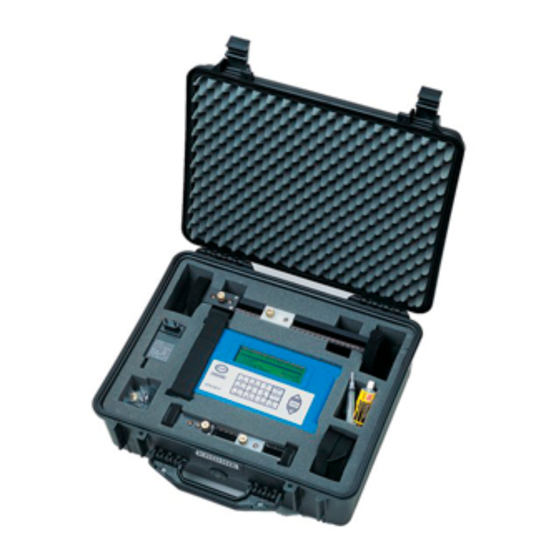
UFM 610 P parts & accessories The UFM 610 P is supplied in a rugged IP65 carrying case. The equipment is housed in a foam insert to give added protection for transportation. STANDARD PARTS Electronic instrument with backlit graphic display Logger included as standard. -
Page 11: Temperature Indication/Range
By selecting keys 4, 7, 8 and 9 it is possible to change the velocity and volumetric flow reading. Press the key more than once to change the display. Press 4 > m/s, Press 4 > f/s Press 7 > l/s, Press 7 > l/min Press 8 >... - Page 12 2.7.1 Transducer set "A" single core coax socket single core coax socket four pin socket separation floating block fixed block distance Figure 7 2.7.2 Transducer set "B" and "C" single core coax socket single core coax socket four pin socket separation floating block fixed block...
-
Page 13: Separation Distance
2.7.4 Transducer set "B" and "C" There are two types of transducer block available that both fit into guiderail “B”. One pair for standard velocity on pipes 90mm to 1000mm, the second pair “C” are for higher velocity flow in pipes 300mm to 2000mm inside diameter. Magnetic attachments are available to fit onto these guiderails as a standard they are supplied with chains. - Page 14 2.9.2 Reflex mounting assembly - Transducer sets "B" and "C" separation distance fixed transducer floating transducer magnets magnets webbing straps Figure 10 2.9.3 Diagonal beam mounting hardware for transducer sets "B" & "C" separation fixed transducer distance WEBBING STRAPS floating transducer Figure 11...
-
Page 15: Ultrasonic Couplant
2.9.4 Diagonal beam mounting for transducer set "D" separation distance 2.10 Ultrasonic couplant Figure 12 Ultrasonic couplant must be used on the sensor face to interface with the pipe wall. (See Figures 20, 21 & 22). On applications above 100°C high temperature couplant will be required, and is supplied as standard with high temperature sensors. 2.11 Fluid types The type of fluids that can be measured with the UFM 610 P are clean liquids or oils etc. -
Page 16: Programming/Main Menu
PROGRAMMING/MAIN MENU Switch on... KROHNE Press 0 for English Press 1 for French Press 2 for German Press 3 for Spanish Serial 0000 v 2.00 Main menu Press SCROLL up or down to move cursor to required option, then MAIN MENU yy-mm-dd hh:mm:ss press ENTER to select. - Page 17 Use the scroll keys to select the required material then press Select pipe lining material: ENTER. If Other is selected, enter the propagation rate of the Steel lining in metres/sec. Contact KROHNE if this is not known. Rubber Glass Epoxy...
- Page 18 3.2.1 Attach sensors The instrument will now provide the user with details on the type of sensor to be attached to the pipe and the mode of operation. It will also give the approximate maximum flow that can be achieved with the sensors that have been selected. It is possible to change the flow units at this stage to display the ATTACH SENSORS yy-mm-dd hh:mm:ss...
-
Page 19: View/Edit Site Data
READ FLOW now appears on the display. READ FLOW yy-mm-dd hh:mm:ss (ERROR MESSAGES APPEAR HERE) Battery 100% 100.0 Signal Temp + Total 1564 l 20°C - Total The display will now read flow and will default to m/s, unless other units were selected when the instrument displayed the sensor mode and type. - Page 20 Measure option in the QUICK START, but only when the pipe internal diameter is greater then 40 mm, Select fluid type, menu. When Other is selected the user must enter the propagation rate in m/s, this can be supplied by KROHNE or...
-
Page 21: Select Sensorset
3.3.6 Read flow Selecting Read flow now informs the user which sensor set should ATTACH SENSORS yy-mm-dd hh:mm:ss be used, in which mode and the approximate maximum flow rate in the units selected. This can be changed by pressing the appropriate Attach sensor set A in REFLEX mode key. - Page 22 3.4.1 Sensor set Selecting Sensor set gives the choice of using different sensors. The choices that are listed are A,B,C and D. TRANSDUCERS SENSOR FREQUENCY VELOCITY RANGE Set “A” 13mm pipe 2 MHz sensors 0.2 m/sec to 7 m/sec Set “A” 89mm pipe 2 MHz sensors 0.03 m/sec to 3,75 m/sec Set “B”...
-
Page 23: Data Logger (See Also Keypad Options-Data Logger)
3.4.4 Exit and select default sensor Selecting EXIT will take you back to MAIN MENU. Data logger (see also KEYPAD OPTIONS-data logger) The data logger can be accessed when in flow mode via the keypad or from the main menu. Accessing the logger via the keypad when in flow mode allows the user to set up the logger. - Page 24 3.5.2 List block names /list block to view The blocks of data will now appear in groups of 10. Press the LIST BLOCKS yy-mm-dd hh:mm:ss SCROLL key to find the block of data required. When the block number is found, press enter to return to the DATA LOGGER menu. 1.Pump room 6.xxxxxxxxxxxxxxx Scroll down to Next block to view and enter the number selected...
- Page 25 3.5.5 Graph as axis maximum The Y axis defaults to the maximum flow achievable with the sensors that have been selected from the data entered, but can be adjusted to increase the resolution of the graph. This example shows the flow is constantly at maximum flow rate. Y AXIS max.
- Page 26 3.5.7 Example It may be that data has been recorded in blocks 1 to 7 but only information in blocks 1 to 3 are required. This is done by selecting 1 as the first block to download and 3 as the last block to download, scrolling back up to download range to RS232 and pressing ENTER, will download the data required.
-
Page 27: Download Data To Windows '95
Download data to Windows '95 KROHNE suggests when downloading to a P.C. that Handshaking = None is selected (See 3.8 - SET UP RS232) when setting up the RS232 for maximum data transfer speed. Check there is data to download by selecting view text in the DATA LOGGER menu. - Page 28 The heading Phone Number will appear. Select Connect using:, then Direct to Com 2. When this has been selected the heading Com 2 Properties will appear, select SET UP RS232 yy-mm-dd hh:mm:ss Handshaking(flow control/Protocol) none Baud rate(Bits per second) 19200 Data bits Stop bits Parity...
-
Page 29: Download Data To Windows 3.1
Data cannot be entered onto a spreadsheet unless it has been stored to a file. KROHNE suggests when downloading to a P.C. Handshaking = None is selected (See 3.8 - Set Up RS232) when setting up the... - Page 30 Select Program Manager then Accessories. Now select Settings and Communications from the Terminal Window. The following will be displayed. also known as Handshaking or Protocol Check now that the above settings are the same as the settings on the UFM 610 P. This can be done from Read flow mode using the RS232 key or from the MAIN MENU and Set up RS232.
-
Page 31: Main Menu Set Up Rs232
Pressing Download Range to RS232 on the UFM 610 P will now display the following in the Terminal window. Press STOP when complete and escape. At this point you can go into the spreadsheet to find the file under a text format. 3.7.2 Example from Excel By selecting OK at this point it is possible to follow the... -
Page 32: Set Up Ufm 610 P
For Data bits, Stop bits, Parity and New line, scroll down these options in the SET UP RS232 and press ENTER to bring up selection. Scroll down the options and press ENTER to select. Printer test confirms the settings which will be displayed or printed and that there is a connection to the UFM 610 P. - Page 33 When the 4mA is adjusted press ENTER. If the 4-20mA is not CALIBRATE 4-20mA yy-mm-dd hh:mm:ss connected then the instrument will still display the DAC number but display Error instead of OK. Adjust the output current to 4mA Use UP/DOWN to set, 5/6 to trim DAC value: 8590 mA OK Press ENTER when done Now adjust the 20mA, press ENTER when complete and the...
-
Page 34: Main Menu Read Flow
3.9.4 Sensor parameters This facility allows KROHNE or the user to program the instrument to accept different sensor sets in the future, if and when they become available. Instructions for this are included for each new sensor. The instrument is already programmed to use sensor set supplied. - Page 35 Pressing ENTER now will make the instrument search for a ATTACH SENSORS yy-mm-dd hh:mm:ss temperature signal. If this is not found then the display will read No signal from temp sensor the following. Press ENTER to try again or SCROLL to enter a value The user can now enter a temperature value between -20°C and +220°C, press ENTER for the separation distance.
-
Page 36: Key Pad Options
KEY PAD OPTIONS The output options can only be adjusted/operated in flow mode. Logger The data logger can only be set up from flow mode and is accessed via the keypad. Once the logger is recording only some parameters can be changed. By pressing the logger key the display will read the following DATA LOGGER yy-mm-dd... -
Page 37: 4-20 Ma Key
Memory free, List block names, Next block to view, View log as text, View log as graph, Units, Graph Y axis max, Clear log and Exit are the same as described on 3.5 - Main Menu - Data Logger. 4-20 mA Key The 4-20mA output can be scaled to whatever the maximum flow rate is. -
Page 38: Rs232 Output Key
4.2.4 Flow at max. output This sets the output at the top end of the scale so that the maximum flow gives 20mA (or 16mA). The instrument automatically defaults to the maximum flow rate, but by pressing ENTER the user can scale the output to any level required. When selected press ENTER to continue. -
Page 39: Options Key
(See 3.10 - Read Flow - Attach sensors). KROHNE cannot guarantee measuring flows below this range because of instabilities in measuring, but it is possible for the user to cancel any cut-off altogether. - Page 40 4.6.2 Set zero flow On some applications and in some conditions it may be that SET ZERO FLOW yy-mm-dd hh:mm:ss although there is no flow the instrument may show a small offset due to picking up noise. This is an offset that can be cancelled out Stop the flow COMPLETELY and then and will increase the accuracy of the instrument.
- Page 41 4.6.7 Correction factor This is a facility that can be used when errors occur due to lack of straight pipe or the sensors have been placed too close to a bend, this could give an incorrect reading to what is expected. The user can set this as a % in the same way as the calibration factor, but it will not be stored in the memory.
- Page 42 This is the sound speed of the fluid calculated using the data entered by the user and the prop measurement. This value may be subject to errors due to small pipe dimension errors especially on smaller pipes. KROHNE recommend the use of tabulated values (See 6.9).
-
Page 43: Status/Error/Warning Messages
STATUS/ERROR/WARNING MESSAGES There are three types of message that will appear and they are Status, Error and Warning. These messages appear under the time and date on the display when in flow mode. Status messages 5.1.1 S1: Initialising Appears when first entering flow mode to show instrument is starting up. 5.1.2 S2: Logging to memory This informs the user that the instrument is logging to the internal memory. -
Page 44: Other Messages
5.3.2 W2: Signal timing poor Unstable signal timing or differing up/down stream times indicate that the liquid is aerated or pipe surface is of poor quality. 5.3.3 W3: No prop signal This occurs when the fixed transducer is unable to transmit and receive a signal across the pipe, for the same reasons as explained in E2. - Page 45 5.4.2 Wall thickness out of range The wall thickness that has been entered is out of range of the instrument. 5.4.3 No data exists for this sensor A sensor has been selected that is not available for use. 5.4.4 Lining thickness out of range The pipe lining thickness has been incorrectly entered.
- Page 46 5.4.9 Enter a lining thickness first This message appears when in VIEW/EDIT SITE DATA the user has tried to enter a pipe lining material before entering a thickness.
-
Page 47: Application Information
APPLICATION INFORMATION The UFM 610 P is a Transit Time ultrasonic flowmeter that has been designed to work with Clamp On transducers, thus enabling liquid flowing within a closed pipe to be measured accurately without the need for any mechanical parts to be inserted either through the pipe wall or protrude into the flow system. -
Page 48: Transducer
When ultrasound is transmitted from Transducer “X” to Transducer “Y” (REFLEX MODE) or Transducer “X” to “Z” (DIAGONAL MODE) the speed at which the sound travels through the liquid is accelerated slightly by the velocity of the liquid. If sound is transmitted in the opposite direction from “Y” to “X” or “Z” to “X”, it is decelerated because it is travelling against the flow of the liquid. -
Page 49: Mounting The Transducers
INCORRECT CORRECT FLOW FLOW > 20 D < 20 D 10 D FLOW FLOW The minimum length of upstream straight pipe is 20 Diameters and 10 Diameters downstream which ensures that accurate Figure18 results will be achieved. Flow measurements can be made on shorter lengths of straight pipe down to 10 Diameters upstream and 5 Diameters downstream, but when the transducers are sighted this close to any obstruction errors can be considerable. - Page 50 For all small pipes below 89mm, using 2MHz transducers, the bead of couplant used must be approximately 20mm long and 2mm maximum diameter for the moveable sensor and 30 long and 2mm diameter for the fixed sensor. Using more couplant could cause wall signals to be generated which cause errors in measurement.
-
Page 51: Liquid Conditions
6.2.3 Transducer set "D" The two 0.5 MHz transducer blocks are the same, there is no propagation rate measurement required when using transducer set “D”. Couplant Figure 22 5. Strap the guide rail assembly to the pipe so that it is perfectly parallel to the pipe axis. 6. -
Page 52: Propagation Velocity
Propagation velocity To make a flow measurement using the UFM 610 P on any liquid, it is necessary to know the propagation velocity in metres/second. There is a short list of fluids that appear on the display when programming (See page 16), showing water and various other liquids. - Page 53 Diagonal 110mm Reflex 110mm Reflex 89mm Diagonal 50mm Reflex 50mm Reflex 13mm DIAGONAL MPS 0.03 0.06 0.13 6.10 13.47 REFLEX MPS 0.03 0.08 3.03 3.78 6.70 8.63 Default Pipe Size Range Figure 24 Diagonal 2500mm Reflex 2500mm Diagonal 2000mm Reflex 2000mm Diagonal 300mm Reflex 300mm Diagonal 150mm...
-
Page 54: Liquid Sound Speed
Liquid sound speed Liquid Sound Speeds at 25°C ∆ Substance Form Index Specific Gravity Sound Speed v/ºC -m/s/ºC Acetic anhydride 1.082 (20ºC) 1180 Acetic acid, anhydride 1.082 (20ºC) 1180 Acetic acid, nitrile 0.783 1290 Acetic acid, ethyl ester 0.901 1085 Acetic acid, methyl ester 0.934 1211... - Page 55 Dichloro methane 1.327 1070 3.94 1,1-Dichloro-1,2,2,2 tetra fluoroethane CClF -CClF 1.455 665.3 3.73 Diethyl ether 0.713 4.87 Diethylene glycol, monoethyl ether 0.988 1458 Diethylenimide oxide 1.00 1442 1,2-bis(DiFluoramino) butane 1.216 1000 1,2bis(DiFluoramino)- 2-methylpropane 1.213 1,2bis(DiFluoramino) propane 1.265 2,2bis(DiFluoramino) propane 1.254 2,2-Dihydroxydiethyl ether 1.116 1586...
- Page 56 Mesityloxide 0.85 1310 Methane 0.162 405(-89.15ºC) 17.5 Methanol 0.791 (20ºC) 1076 2.92 Methyl acetate 0.934 1211 o-Methylaniline 0.999 (20ºC) 1618 4-Methylaniline 0.966 (45ºC) 1480 Methyl alcohol 0.791 (20ºC) 1076 2.92 Methyl benzene 0.867 1328 4.27 2-Methyl-butane 0.62 (20ºC) Methyl carbinol 0.789 1207 Methyl-chloroform...
- Page 57 Refrigerant 21 CHCl 1.426 (0ºC) 3.97 Refrigerant 22 CHClF 1.491 (-69ºC) 893.9 4.79 Refrigerant 113 F-CClF 1.563 783.7 3.44 Refrigerant 114 CClF -CClF 1.455 665.3 3.73 Refrigerant 115 656.4 4.42 Refrigerant C318 1.62 (-20ºC) 3.88 Selenium 1072 0.68 Silicone (30 cp) 0.993 Sodium fluoride 0.877...
-
Page 58: Solid Sound Speeds
6.10 Solid sound speeds 1. Use Shear Wave for “A” & “B” Transducers 2. Use Long Wave for “C” & “D” Transducers Material Shear Wave m/s Long Wave m/s Steel 1% Carbon (hardened) 3150 5880 Carbon Steel 3230 5890 Mild Steel 3235 5890 Steel 1% Carbon... -
Page 59: Technical Data
BH21 7PG. The unit was tested with all cables as supplied of a maximum length of 3m. While the operation of the unit may not be affected by the use of longer cables, KROHNE can make no statement about conformance to the above standards when these cables are in use. -
Page 60: Warranty
In addition, the "General conditions of sale" forming the basis of the purchase contract are applicable. If flowmeters need to be returned to KROHNE, please note the information given on the last-but-one page of these instructions. KROHNE regrets that it cannot repair or check your flowmeter(s) unless accompanied by the completed form sheet. - Page 61 IF YOU NEED TO RETURN FLOWMETERS FOR TESTING OR REPAIR TO KROHNE, PLEASE OBSERVE FOLLOWING: Your ultrasonic flowmeter has been supplied by a company if it is accompanied by a certificate in line with the following with ISO 9001 certification model confirming that the flowmeter is safe to handle.
Need help?
Do you have a question about the ALTOSONIC UFM 610 P and is the answer not in the manual?
Questions and answers