Table of Contents
Advertisement
Quick Links
KROHNE 11/2003
©
7.30926.31.00
GR
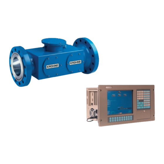
Ultrasonic Flowmeters
ALTOSONIC V
Addition to the installation and operating instructions
EEx Operating Manual
UFC/V...-EEx ultrasonic flow converter
UFS 500 F/5STR/...-EEx flow sensor
Variable area flowmeters
Vortex flowmeters
Flow controllers
Electromagnetic flowmeters
Ultrasonic flowmeters
Mass flowmeters
Level measuring instruments
Communications technology
Engineering systems & solutions
Switches, counters, displays and recorders
Heat metering
Pressure and temperature
Advertisement
Table of Contents

Related Manuals for KROHNE ALTOSONIC V


Summary of Contents for KROHNE ALTOSONIC V
- Page 1 KROHNE 11/2003 © 7.30926.31.00 Ultrasonic Flowmeters ALTOSONIC V Addition to the installation and operating instructions EEx Operating Manual UFC/V...-EEx ultrasonic flow converter UFS 500 F/5STR/...-EEx flow sensor Variable area flowmeters Vortex flowmeters Flow controllers Electromagnetic flowmeters Ultrasonic flowmeters Mass flowmeters...
- Page 2 Install and connect cabling proper to exclude damage or harmful situations. • If the instrument does not operate normally, refer to the service instructions or refer to qualified KROHNE service engineers. • There are no operator-serviceable parts inside the instrument.
- Page 3 This manual and all other documents are subject to change without prior notice. • KROHNE will not be liable for any damage of any kind by using its instrument, including, but not limited to direct, indirect, incidental, punitive and consequential damages.
- Page 4 KROHNE Altometer Kerkeplaat 12 3313 LC Dordrecht The Netherlands For information, maintenance or service please contact your nearest local KROHNE representative. WARNING ! No changes may be made to the devices. Unauthorized changes might affect the explosion safety of the devices.
-
Page 5: Table Of Contents
Table of Contents System components................2 General information ..................2 Flow Sensor ....................2 Flow Converter.................... 2 1.3.1 Versions............................2 1.3.2 Cable and conduit entries......................3 1.3.3 Warning messages........................3 1.3.4 Heating element and thermostats ....................3 Electrical connections ...............5 Equipotential bonding system ..............6 Connecting cables .................. -
Page 6: System Components
1. System components General information The ALTOSONIC V ultrasonic flowmeter system, consisting of a combination of the UFS 500 F/5STR-EEx Ultrasonic Flow Sensor and the UFC-V/…-EEx Ultrasonic Flow Converter, in separate design, is in accordance with the European Directive 94/9 EG (i.e. ATEX 100a) and approved for hazardous classified locations of Zone 1 and 2 by the PTB conform to the European Standards of the EN 500xx series. -
Page 7: Cable And Conduit Entries
+5°C to +55°C. It is set at +5°C, which means that the heating element will continue to heat up the air in the box until it reaches a temperature of +5°C, at which thermostat T1 will interrupt the power supply of the heating element. ALTOSONIC V... - Page 8 UFC 500…-EEx units are provided with the supply power and start operating. Installation, setting and checking of the right functioning of the heating element and the thermostats T1 and T2 is done by KROHNE. Optional heating for standard UFC-V/EEx To prevent condensation inside the flameproof box of the standard version type UFC-V/EEx can optionally be provided with a heating element of maximum 30 W.
-
Page 9: Electrical Connections
The SMB plugs that are to be connected to these receptacles are marked by a yellow plastic tubing with the matching black printed number. Equipotential bonding is established via the external bolt, which is screwed into a bulge on the outside of the box at the base. ALTOSONIC V... -
Page 10: Equipotential Bonding System
(e.g. DIN VDE 0165). ≥ 500 V Rated voltage: Examples: H07..-., H05..-. Cable C: Quad coaxial cable. Type MR04 (supplied by KROHNE). Technical data: ≥ 500 V Test voltage: ≥ 0.1 mm Diameter of strand (core and screen):... -
Page 11: Connection Diagram
10x SMB connections for intrinsically safe sensor circuits of Zone 1 and 2 5-beam flow tube Entity parameters: UFS 500 F/5STR/…-EEx = 13.1 V Primary Head = 600 mA = 3.9 nF Intrinsically safe sensor circuits = 38.3 µH ALTOSONIC V... -
Page 12: Service And Maintenance
Contact KROHNE for the ordering information of spare parts or replacements of UFC 500/…- EEx electronics units and/or power fuses. -
Page 13: Replacement Of Electronics Unit
Refer to standard installation and operating instructions for information about resetting and reprogramming the new electronics unit after replacement. Important customer specific data should be recorded before replacing the electronics unit(s)! Before commencing work, note the "Before opening" instructions, then continue as follows: ALTOSONIC V... -
Page 14: Replacement Of Power Fuse(S)
(T200mA for 100/115V AC and T125mA for 200/230 V AC). See also the yellow sticker that is glued on the mains transformer as shown in the figure on the previous page. 4. Reassemble the unit in reverse order (points 2 and 1). Note the "After opening" instructions during reassembling. ALTOSONIC V... -
Page 15: Ac/Dc Version
Plug the numbered SMB connectors to the corresponding numbered SMB receptacles on the electronics unit. 6. Close the cover of the flameproof box and screw all bolts tightly with the right size socket- head screw wrench. Note the "After opening" instructions during reassembling. ALTOSONIC V... -
Page 16: Appendix 1 Type Examination Certificate
Appendix 1 Type Examination Certificate PTB Certificate PTB 01 ATEX 2012 EEx UFS 500 F/…/…/…-EEx German original page ALTOSONIC V... - Page 17 ALTOSONIC V...
- Page 18 ALTOSONIC V...
- Page 19 PTB Certificate PTB 01 ATEX 2012 EEx UFS 500 F/…/…/…-EEx English translation page 1-3 ALTOSONIC V...
- Page 20 ALTOSONIC V...
- Page 21 ALTOSONIC V...
- Page 22 KEMA ATEX certificate 02ATEX2168 ALTOSONIC V UFC-V/EEx and UFC-V/LT-EEx ALTOSONIC V...
- Page 23 ALTOSONIC V...
- Page 24 ALTOSONIC V...
- Page 25 ALTOSONIC V...
-
Page 26: Appendix 2 Declaration Of Conformity
Appendix 2 Declaration of Conformity ALTOSONIC V... -
Page 27: Appendix 3 Data Plates
30 W heater Low-temperature version UFC-V/LT-EEx UFS 500 F/5STR-EEx Flow Sensor (cable gland design) NOTE: The heating element may have a maximum power dissipation of 200 W. The current heating element has a power dissipation of approx. 130 W. ALTOSONIC V... - Page 28 FAX: +34(0)91-8 83 48 54 Netherlands Controles Automaticos Ltda. e-mail: krohne@krohne.es Italy Estrada Das Águas Espraiadas, 230 C.P . 56 KROHNE Oil & Gas B.V. 06835 - 080 EMBU - SP KROHNE Italia Srl. Switzerland Kerkeplaat 18 TEL.: +55(0)11-4785-2700 Via V. Monti 75...
Need help?
Do you have a question about the ALTOSONIC V and is the answer not in the manual?
Questions and answers