Advertisement
Quick Links
DIN A4: 7.10028.31.00
©
KROHNE 06/2005
GR
Subject to change without notice.
7.30934.32.00
Short form installation
and operating instructions
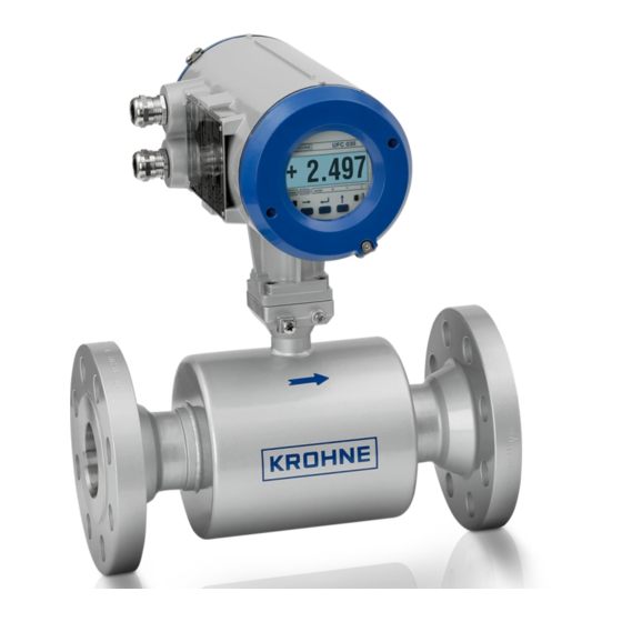
Universal 3-Beam
ultrasonic flowmeter
UFM 3030 ultrasonic flowmeter
UFC 030 ultrasonic flow converter
UFS 3000 ultrasonic flow sensor
Electromagnetic flowmeters
Variable area flowmeters
Mass flowmeters
Ultrasonic flowmeters
Vortex flowmeters
Flow controllers
Level measuring instruments
Pressure and temperature
Heat metering
Communications technology
Switches, counters, displays and recorders
Engineering systems & solutions
Advertisement


Need help?
Do you have a question about the UFM 3030 and is the answer not in the manual?
Questions and answers