Table of Contents
Advertisement
Quick Links
©
KROHNE 07/2002
7.02254.21.00
Addition to the
installation and
operating instructions
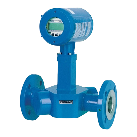
UFM 500 K - EEx ATEX
Ultrasonic
compact flowmeter
Variable area flowmeters
Vortex flowmeters
Flow controllers
Electromagnetic flowmeters
Ultrasonic flowmeters
Mass flowmeters
Level measuring instruments
Communication technology
Engineering systems & solutions
Preasure and temperature
Advertisement
Table of Contents

Subscribe to Our Youtube Channel
Summary of Contents for KROHNE UFM 500 K EEx
- Page 1 © KROHNE 07/2002 7.02254.21.00 Addition to the installation and operating instructions UFM 500 K - EEx ATEX Ultrasonic compact flowmeter Variable area flowmeters Vortex flowmeters Flow controllers Electromagnetic flowmeters Ultrasonic flowmeters Mass flowmeters Level measuring instruments Communication technology Engineering systems & solutions...
-
Page 2: Table Of Contents
WARNING ! No changes may be made to the devices. Unauthorized changes might affect the explosion safety of the devices. These additional instructions are an extension to the standard Installation and Operating Instructions and only applies for the EEx version of the UFM 500 K compact ultrasonic flowmeter. -
Page 3: System Components
1. SYSTEM COMPONENTS 1.1 General information The Altosonic UFM 500 K-EEx ultrasonic compact flowmeter is in accordance with the European Directive 94/9 EC (ATEX 100a) and approved for hazardous classified locations of Zone 1 and 2 by the PTB conform to the European Standards of the EN 500xx series. The UFM 500 K-EEx has the following approval number. -
Page 4: Signal Converter
1.3 UFC 500-EEx signal converter The UFC 500-EEx signal converter consists of a cylindrical housing made of die-casted aluminum. It has of two separate compartments, divided from each other by an integrated wall with casted flameproof terminal feed-through. The interconnecting part to the primary head at the bottom of the housing contains a flameproof wire or coaxial cable feed-through. -
Page 5: Electrical Connection
2. ELECTRICAL CONNECTION NOTE: All the connecting cables that enter the terminal compartment of the UFC 500-EEx signal converter (i.e. power supply, current and binary in-/outputs cables) are not intrinsically safe ! The arrangement of the terminals in the terminal compartment is shown in Figure 1 below. For mains voltages above 50 Vac the PE conductor must be connected to the PE-terminal in the terminal compartment. -
Page 6: Operation Of The Signal Converter
B1 B⊥ B2 I+ I I ≤ 150 mA I ≤ 150 mA Ri ≤ 680 Ω Electronic e.g. signal electro- indicator mechanical totalizer ≤ 32V /24 V Figure 2: Passive pulse/status output. Figure 3: Active current output. NOTE: The status output (terminals B1, B⊥ and B2) can only be configured as passive outputs, the current output (terminals I+ and I) can only be configured as active output. -
Page 7: Connection Diagram
4. CONNECTION DIAGRAM PE 100-240V AC FE 24-48V AC SIGNAL IN-/OUTPUTS L~ L~ FE 24V AC/DC UFC 500…-EEx Signal Converter B1 B⊥ B2 I+ BINARY CURRENT MAINS OUTPUTS OUTPUT SUPPLY TERMINAL COMPARTMENT Standard "EEx e" (optional "EEx d") ELECTRONICS COMPARTMENT Always "EEx d"... -
Page 8: Service
5. SERVICE 5.1 Replacement of electronics unit or mains fuse(s) IMPORTANT ! The following instructions must be followed carefully, if the flameproof UFM 500 K-EEx signal converter housing has to be opened respectively closed again ! Before opening: ♦ Make absolutely sure that there is no explosion hazard ! ♦... -
Page 9: Replacement Of Electronics Unit
5.1.1 Replacement of electronics unit See the standard Installation and Operating Instructions for detailed information about resetting and reprogramming the new electronics unit after replacement. Important customer specific data (like the value of the internal totalizer) should be noted before replacing the electronics unit ! note the instructions in Section 4.1 ("Before opening") Before commencing work,... - Page 10 Mains transformer Indication of 115/230 V version voltage selector (black dot = notch) Sticker with fuse rating Mains fuse F1 (in fuse -holder) Voltage selector Figure 6: Power supply version 115/230 V AC. b) 24 V AC/DC version note the instructions in Section 4.1 ("Before opening") Before commencing work, Then continue as follows: 1.
- Page 11 Location of mains fuses (see detail in Figure 8) Figure 7: UFC 500-EEx electronics unit with 24 V AC/DC power supply. Figure 8: Location of fuses F1, F2 on 24 V AC/DC unit.
-
Page 12: Changing Power Supply Voltage (Not For 24 V Ac/Dc Version)
Carefully keep the coaxial cables to the side of the housing, while inserting or removing the electronics unit into respectively from the converter housing. This is to prevent damaging of the coaxial cables ! 6. SPARE PARTS UFC 500-EEx Krohne part no. Type of mains fuse(s) Krohne part no. electronics unit 230 Vac T125H250V (to IEC 60127-2) 5.06627.00.00... -
Page 13: Ec-Type Examination Certificate
8. EC-TYPE EXAMINATION CERTIFICATE Translation in English. - Page 14 EC-type examination certificates, translation in English continued.
- Page 15 EC-type examination certificate, original in German.
- Page 16 EC-type examination certificate, original in German continued.
-
Page 17: Declaration Of Conformity
9. DECLARATION OF CONFORMITY... -
Page 18: Data Plate
10. DATA PLATE... - Page 19 TEL.: +41(0)61-638 30 30 FAX: +49(0)203-301 389 e-mail: krohne@krohne.it FAX: +41(0)61-638 30 40 e-mail: export@krohne.de China e-mail: info@krohne.ch KROHNE Measurement Instruments Co. Ltd. Korea Room 7E, Yi Dian Mansion Hankuk KROHNE United Kingdom 746 Zhao Jia Bang Road 2 F, 599-1 KROHNE Ltd.


Need help?
Do you have a question about the UFM 500 K EEx and is the answer not in the manual?
Questions and answers