Table of Contents
Advertisement
DIN A4: 7.10028.31.00
©
KROHNE 06/2005
GR
Subject to change without notice.
7.30942.32.00
Addition to the installation
and operating instructions
Universal 3-Beam
ultrasonic flowmeter
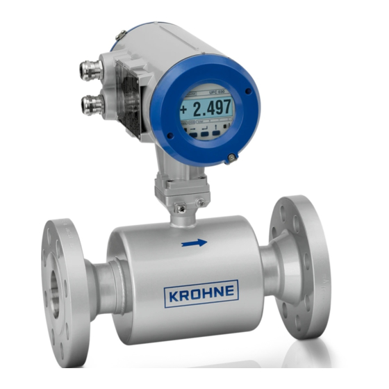
UFM 3030 K/...EEx compact ultrasonic flowmeter
UFC 030 F/...EEx ultrasonic flow converter
UFS 3000 F/...EEx ultrasonic flow sensor
Electromagnetic flowmeters
Variable area flowmeters
Mass flowmeters
Ultrasonic flowmeters
Vortex flowmeters
Flow controllers
Level measuring instruments
Pressure and temperature
Heat metering
Communications technology
Switches, counters, displays and recorders
Engineering systems & solutions
Advertisement
Table of Contents

Related Manuals for KROHNE UFM 3030 K EEx Series


Summary of Contents for KROHNE UFM 3030 K EEx Series
- Page 1 DIN A4: 7.10028.31.00 © KROHNE 06/2005 7.30942.32.00 Addition to the installation and operating instructions Universal 3-Beam ultrasonic flowmeter UFM 3030 K/…EEx compact ultrasonic flowmeter UFC 030 F/…EEx ultrasonic flow converter UFS 3000 F/…EEx ultrasonic flow sensor Electromagnetic flowmeters Variable area flowmeters...
- Page 2 Install and connect cabling proper to exclude damage or harmful situations. • If the product does not operate normally, refer to the service instructions or refer to qualified KROHNE service engineers. • There are no operator-serviceable parts inside the product.
- Page 3 • KROHNE will not be liable for any damage of any kind by using its instrument, including, but not limited to direct, indirect, incidental, punitive and consequential damages. •...
- Page 4 WARNING! No changes may be made to the devices. Unauthorized changes might affect the explosion safety of the devices. Be sure to follow these instructions! • IMPORTANT! The prescriptions and regulations as well as the electrical data described in the EC type examination certificate must be obeyed.
-
Page 5: Table Of Contents
Table of contents System Components General information Compact flowmeter Flow sensor Flow converter Electrical data Technical data Mains supply Signal in-/outputs Ultrasonic sensor circuits Environment temperatures Power dissipation Electrical connections Safety instructions Power supply connection Equipotential bonding Standard versions Namur versions MODIS versions Operation of the flow converter Operation of the flow converter... -
Page 6: System Components
System Components General information The UFM 3030 ultrasonic flowmeters in compact and separate design are in accordance with the European Directive 94/9 EC (ATEX 100a) and approved for hazardous classified locations of Zone 1 and 2 by the PTB conform to the European Standards of the EN 500xx series, approval number: PTB 03 ATEX 2021 X. -
Page 7: Flow Sensor
Flow sensor 1.3.1 Standard instruments The UFS 3000…-EEx flow sensor is the default measuring unit of the UFM 3030 (3-beam) ultrasonic flowmeters. It contains the ultrasonic sensor (three pairs of opposite transducers) in type of protection intrinsic safety category "ib" according to EN 50020. All sensor circuits are wired by separate coaxial cables and connected through SMB connectors, which are marked by the respective numbers 1.1, 1.2, 2.1, 2.2, 3.1 and 3.2. -
Page 8: Flow Converter
1.3.2 Optional instruments The following options are available to support customers that have one or more ultrasonic flowmeter systems (in compact and/or separate design) based on the UFM 500…-EEx series and need to replace the UFC 500…-EEx electronics unit. Because the intrinsically safe “ib” sensor circuits of UFS 500…-EEx flow sensor have almost the same maximum values (i.e. - Page 9 The UFC 030…-EEx electronics unit is inserted into the electronics compartment with the help of two sliding rubbers that position and fixate the unit at the front of the inside of the housing. Two M4 screws mount the unit and a third M4 screw fixates the brass earth strip at the back-end of the front- end printed circuit board, which contains the integrated voltage/current limiting circuit.
- Page 10 “EEx d” approved cable glands are no part of the standard delivery package, but must be provided by the customer himself or ordered explicitly at KROHNE. 1) Semi-circular insulating cover plate 2) U-clamp terminal size M4 (7 in total) 3) Dividing plate of insulating material (8 in total)
-
Page 11: Electrical Data
Electrical data 1.5.1 Power supply unit The UFC 030…-EEx electronics unit is equipped with a switching-mode power supply, which is available in two supply voltage ranges, namely: • 100…240 V AC power supply; • 24 V AC/DC power supply. The power supplies are available in the standard as well as the MODIS design. The main difference between these versions is that the MODIS versions are not provided with the analogue input A1 and its driver logic. - Page 12 (close to the local display unit). The connections are established during the installation of the IFC 030…-EEx electronics unit inside the flameproof electronics compartment of the flow converter housing by KROHNE Altometer personnel. 1.5.3 In-/output circuits The analogue input circuit A1 is protected against overcurrent by a fuse of type TR5 No.
-
Page 13: Technical Data
Technical data Mains supply Connector X1, pins 6 and 7 on power supply PCB 24 V AC/DC 24 V AC +15%/-10%, 8 W, Vm = 264 V 24 V DC +33%/-25%, 8 W, Vm = 264 V 100…240 V AC 100…240 V AC -15%/+10%, 11 W, Vm = 264 V Signal in-/outputs Standard versions... -
Page 14: Electrical Connections
Electrical connections Safety instructions These instruments are designed in accordance with IEC 61010-1 for Installation Category 2 and Pollution Degree 2. Hazardous voltages are present within this product during normal operation. They are designed for Protection Class I and should never be operated without protective earthing. The instruments shall also never be operated with the covers removed. -
Page 15: Standard Versions
Standard versions The field cables enter the terminal compartment of the UFC 030…-EEx flow converter unit (i.e. power supply, current and signal in-/outputs) and are non-intrinsically safe. To connect external devices to the in-/output terminals, the wiring requirements for the type of protection of the compartment (standard: increased safety "e", optional: flameproof "d") must be conform to the international or national standard involved (e.g. -
Page 16: Namur Versions
Namur versions See connection diagram below for standard version with NAMUR outputs (non-MODIS) See paragraph 4.4 how to set-up the NAMUR NE 43 failure indication Symbols and specifications Milliampère meter Ri ≤ 680 Ohm Electronic or electro-mechanical totalizer U ≤ 32 V DC / 24 V AC; I ≤ 150 mA Switch, N/O contact 32 V DC / 1.5 mA External power supply, DC voltage = 15 –... -
Page 17: Modis Versions
MODIS versions The field cables of the non-intrinsically safe power supply and the intrinsically safe "ia" signal in- /outputs enter the terminal compartment of the UFC 030i-EEx flow converter unit via two separate entrances. To connect external devices to the intrinsically safe signal output terminals, the wiring requirements for their type of protection as well as of the compartment (standard: increased safety "e", optional: flameproof "d") must be conform to the international or national standard involved (e.g. - Page 18 Passive counter with external power supply (*) Only if measuring devices are explosion protected! UFM 3030...
- Page 19 MODIS signal in- and output connections (*) Only if measuring devices are explosion protected! UFM 3030...
-
Page 20: Operation Of The Flow Converter
(e.g. DIN VDE 0165). Rated voltage: ≥ 500 V Examples: H07..-., H05..-. to HD 21.S2 or HD22.S2 Cable C MR06 coaxial cable (only for remote default version), to be supplied by KROHNE Altometer. Technical data: Test voltage: ≥ 500 V Diameter of strand (core and screen): ≥... -
Page 21: Connection Diagrams
Connection diagrams The following diagrams show the connection diagrams of respectively the compact ultrasonic flowmeter system and remote ultrasonic flowmeter system (default). The picture in the frame shows the connecting terminals of the UFC 030i-EEx (non-MODIS version) electronics unit. UFM 3030 K/…EEx compact flowmeter UFM 3030... - Page 22 UFS 3000 F/…EEx (sensor) + UFC 030 F/…EEX (converter) with connection cable between sensor and converter. UFM 3030...
- Page 23 The following figures show the connection diagram of the optional versions, i.e with UFS 500…-EEx flow sensor. Note in this case two of the intrinsically safe sensor outputs of the UFC 030…-EEx electronics unit (no. 3.1 and 3.2) are not connected. UFM 530 K/…EEx compact flowmeter (option) for High Pressure UFM 3030...
- Page 24 UFS 500 F/…EEx (sensor) + UFC 030 F/…EEx (converter), optional for High Temperature / High Pressure with connection cable between sensor and converter. UFM 3030...
-
Page 25: Namur Ne 43 Settings
Namur NE 43 settings The UFM 3030…EEx and UFC 030…EEx can be set-up such that the Current Output functions are according to Namur NE 43. This means the current will go either to 3.6 or to 21.5 mA (failure value can be user defined, normal operating limits are between 3.8 and 20.5 mA) in case the instrument indicates a failure. -
Page 26: Service And Maintenance
Service and maintenance Introduction Contact your nearest local KROHNE representative for ordering information of the UFC 030…-EEx electronics units and/or fuses. The UFM 3030 ultrasonic flowmeters are maintenance free with regard to the flow metering properties. Within the scope of the periodical inspections, which are required for electrical apparatus that is installed and used in a hazardous classified location, it is recommended to check the flameproof converter housing on signs of corrosion and damages. -
Page 27: Replacement Of Electronics Unit
Replacement of electronics unit Refer to the standard installation and operating instructions for detailed information about resetting and reprogramming the new electronics unit after replacement. Important customer specific data (like the value of the internal totaliser) should be noted before replacing the UFC 030…-EEx electronics unit ! Before commencing work, note the “Before opening”... - Page 28 Power supply PCB - 100…240 V AC standard Power supply PCB - 24 V AC/DC standard (non-MODIS). (non-MODIS). UFM 3030...
- Page 29 Appendix 1 Declaration of conformity UFM 3030...
- Page 30 Appendix 2 Data plates UFM 3030 K-EEx + UFM 530 K-EEx UFM 3030 K/i-EEx (MODIS) UFM 3030 K-EEx + UFM 530 K-EEx (NAMUR) UFC 030 F-EEx UFM 3030...
- Page 31 UFC 030 F/i-EEx (MODIS) UFC 030 F-EEx (NAMUR) UFS 3000 F–EEx + UFS 3000 F/XT-EEx UFS 3000 F-EEx (standard version) + UFS 3000 (extended temperature version) F/XT-EEx (extended temperature version) UFS 500 F-EEx + UFS 500 F/HT -EEx UFM 3030...
- Page 32 Notes UFM 3030...
- Page 33 Croatia New Zealand KROHNE Messtechnik KROHNE Austria Ges.m.b.H. Singapore Denmark Pakistan GmbH & Co. KG Modecenterstraße 14 Tokyo Keiso - KROHNE Pte. Ltd. Ecuador Peru Ludwig-Krohne-Str. A-1030 Wien 27 Kian Teck Drive Jurong Egypt Poland D-47058 Duisburg TEL.: +43(0)1/203 45 32...
Need help?
Do you have a question about the UFM 3030 K EEx Series and is the answer not in the manual?
Questions and answers