KROHNE UFM 3030 K EEx Series Service Handbook
Universal 3-beam ultrasonic flowmeter
Hide thumbs
Also See for UFM 3030 K EEx Series:
Table of Contents
Advertisement
DIN A4: 7.10028.31.00
©
KROHNE 06/2005
GR
Subject to change without notice.
7.30935.32.00
Service Handbook
Universal 3-Beam
ultrasonic flowmeter
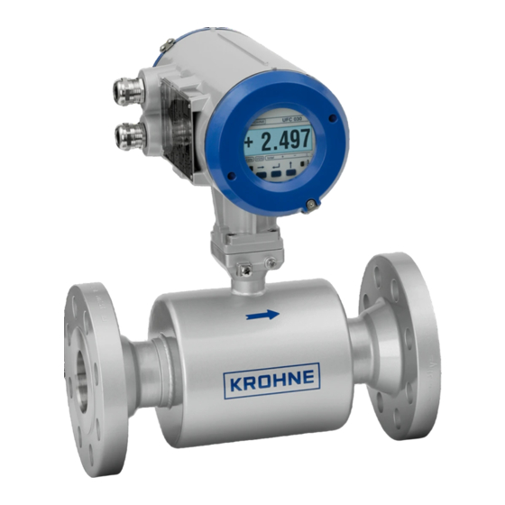
UFM 3030 K/...EEx compact ultrasonic flowmeter
UFC 030 F/...EEx ultrasonic flow converter
UFS 3000 F/...EEx ultrasonic flow sensor
Electromagnetic flowmeters
Variable area flowmeters
Mass flowmeters
Ultrasonic flowmeters
Vortex flowmeters
Flow controllers
Level measuring instruments
Pressure and temperature
Heat metering
Communications technology
Switches, counters, displays and recorders
Engineering systems & solutions
Advertisement
Table of Contents

Related Manuals for KROHNE UFM 3030 K EEx Series


Summary of Contents for KROHNE UFM 3030 K EEx Series
- Page 1 DIN A4: 7.10028.31.00 © KROHNE 06/2005 7.30935.32.00 Service Handbook Universal 3-Beam ultrasonic flowmeter UFM 3030 K/…EEx compact ultrasonic flowmeter UFC 030 F/…EEx ultrasonic flow converter UFS 3000 F/…EEx ultrasonic flow sensor Electromagnetic flowmeters Variable area flowmeters Mass flowmeters Ultrasonic flowmeters...
- Page 2 Install and connect cabling proper to exclude damage or harmful situations. • If the product does not operate normally, refer to the service instructions or refer to qualified KROHNE service engineers. • There are no operator-serviceable parts inside the product.
- Page 3 • KROHNE will not be liable for any damage of any kind by using its product, including, but not limited to direct, indirect, incidental, punitive and consequential damages. •...
- Page 4 Kerkeplaat 12 3313 LC Dordrecht The Netherlands For information, maintenance or service please contact your nearest local KROHNE representative. Notes on the service handbook This service handbook is divided into four parts for easy use. All ultrasonic flow meters are factory- set to your order specifications.
-
Page 5: Table Of Contents
Table of contents Introduction 1.1 Cautions 1.2 Unpacking and inspection 1.3 System description 1.4 Available versions 1.5 CE Approvals Mechanical installation 2.1 Handling the flowmeter 2.2 Installation location and position 2.3 Special installation requirements 2.4 Pipe flanges 2.5 Pipes with cathodic protection Connecting the signal converter 3.1 Safety instructions 3.2 Converter terminal box... -
Page 6: Introduction
• After connecting to the mains, check if there is any indication on the display and if the backlight of the display is lighted. If not, contact your local KROHNE representative for advice. System description The UFM 3030 ultrasonic flow meter is a precision instrument designed for linear, bi/directional flow measurement of liquids. -
Page 7: Available Versions
Pressure Equipment Directive The KROHNE organisation complies with the requirements of Module H of the Pressure Equipment Directive 97/23/EC (full quality assurance). Please refer to the CE declaration for more detailed information. -
Page 8: Mechanical Installation
Mechanical installation Handling the flowmeter Important: Do not lift the compact flowmeter by the signal converter housing or the terminal box. Check the weight of the flowmeter as indicated on the type plate before handling the unit. When handling the flowmeter avoid hard blows, jolts or impacts. -
Page 9: Special Installation Requirements
If required the position of the signal converter can be modified by turning the display circuit board through 90° or 180° to achieve a horizontal position of the display. In addition the signal converter housing may be turned through 90° opposite the flow sensor. For an exact description of this procedure, refer to chapter 8.6. -
Page 10: Pipe Flanges
Since gas will collect at the highest point of a pipe, installation of the flow meter at that location should be avoided at all times. Also installation in a down going pipe should be avoided since a completely filled pipe may not be guaranteed due to cascading affects. Additionally flow profile distortion is possible. -
Page 11: Pipes With Cathodic Protection
1. Flange of flow sensor 2. Gasket 3. Pipe flange 4. Bolt 5. Nut 6. Washer 7. Insulating sleeve Follow grounding instructions. Use ≥ 4 mm2 (≥ AWG 10 cable). Note: No earthing cables are supplied by KROHNE. UFM 3030... -
Page 12: Connecting The Signal Converter
Connecting the signal converter Safety instructions This product is designed for use in accordance with EN IEC 61010-1 for Installation Category 2 and Pollution Degree 2. Hazardous voltages are present within this product during normal operation. The product is designed for Protection Class I and should never be operated without protective earthing. -
Page 13: Connection Of Sensor Cables (Ufm 3030 F Only)
• It is not allowed to use the protective conductor terminal for any other connection than the protective earth conductor. • IP 67 is only warranted when using suitable cabling with the cable glands and covers mounted as specified. The power supply terminals There is a separate earthing has three connections that must be connected:... -
Page 14: Electrical Connection Of The Signal Inputs And Outputs
Electrical connection of the signal inputs and outputs The terminal to connect the electrical signal inputs and outputs consist of 6 connections. For standard instruments For instruments with a communication module For wiring of the signal inputs and outputs it is advised to use unshielded twisted pairs. Internal circuit of the signal inputs and outputs of the converter Terminal... - Page 15 Communication connection+ For fieldbus communication Communication connection - For fieldbus communication P/I/C Combined current output (I) digital See individual I/C terminal and P terminal output (C) and pulse output (P). See specifications. individual I/C terminal and P terminal functions The electrical input and output signals can be connected either in active or in passive mode. In active mode DC supply voltage is provided from the V+ terminal.
-
Page 16: Connection Diagram Examples
Connection diagram examples In the following, some examples of how to connect the electrical input and output signals. Current output Active Passive Ri <= 680 Ω For supply: U = 15 – 24Vdc, I >= 22mA Pulse output Active Passive R1>= 470 Ω, R2 = U*R1/(V+ - U) For supply: U<= 32Vdc, <= 24Vac... -
Page 17: Start-Up
Start-up • Check that the flow meter has been correctly installed. • With separate systems, check before initial start-up that the correct converter (UFC 030 F) is used with the correct flow sensor (UFS 3000). • Order No., see instrument nameplates •... -
Page 18: Operating The Signal Converter
Part B The signal converter Operating the signal converter Front panel and operating keys The front panel and its operating keys are accessible after removing the front (glass) cover of the electronics section using the special wrench supplied with the flowmeter. When removing the cover, do not damage the screw thread and the gasket, never allow dirt to accumulate, and make sure that they are well greased using Teflon grease at all times. -
Page 19: Menu Structure And Function Of Operating Keys
Menu structure and function of operating keys The menu structure consists of 5 user accessible blocks. • Function block 0 Error/Totalizer reset can be accessed from the measuring mode and provides detailed information on errors occurred during operation. It allows for fast and easy resetting of the errors and Totalizers. - Page 20 Measuring mode Menu mode Data level → Go to the parameter setting mode, Go to the next, lower Go to the next function 1.00.00 OPERATION. If access menu level. character or change CODE 1 is activated, CODE 1 must be line (only when 2 lines entered first.
- Page 21 key. 2.02.02 PULSE Test pulse/frequency output 1 Hz 10 Hz 100 Hz 1000 Hz 2000 Hz Use the up arrow to advance. Displayed value directly present at pulse output. Actual value present at output after pressing ↵ key 2.03.00 INPUTS Submenu 2.03.00 Inputs 2.03.01 AN INP 1...
- Page 22 measuring tube. Duration approximately 15s with display indicating "BUSY". STORE NO (preserve old zero value) STORE YES (store new zero value) 3.01.04 MASTER TC Master time constant of display and current output (see Function 1.01.04) Range: 0.02 through 99.99 s 3.01.05 LF CUTOFF Low-flow cut-off for display and outputs (see 1.01.05)
- Page 23 Unit: Celsius or Fahrenheit Range: -50° through 150°C 3.02.04 INP2 4 mA 4 mA Reference for analog input 2 4 mA Temperature reference Unit: Celsius or Fahrenheit Range: -50° through 150°C 3.0205 INP2 20 mA 20 mA Reference for analog input 2 20 mA Temperature reference Unit: Celsius or Fahrenheit Range: -50°...
- Page 24 3.03.08 ERROR MSG Display error messages NO, YES 3.03.09 DATE Display date NO, YES 3.03.10 AN INPUT Display analog inputs NO, YES 3.03.11 SIGN LEVEL Display signal level NO, YES 3.04.00 CURR OUTP Submenu 3.04.00 Current output 3.04.01 FUNCTION Function of current output OFF (switched off) ACT FLOW (actual flow) CORR FLOW (corrected flow), see Function 3.02.02 and 3.02.08...
- Page 25 3.05.02 DIRECTION Direction of pulse output FORWARD (forward flow measurement) BOTH (forward and reverse flow measurement indicating both in the same range) 3.05.03 DIG OUTPUT Function of digital output PATH ERR (measuring path error indication) TOTAL ERR (Totalizer error indication) ALL ERR (indication of all errors) AN INP ERR (analog input error indication OVERRANGE (overrange indication)
- Page 26 3.07.04 LOCATION Tag name setting Free settable tag for identification, maximum 10 characters. Characters assignable to each place: A..Z / blank character / 0..9 Factory setting: KROHNE 3.07.05 UNIT TEXT Text for user-defined unit Definition: volume/time Characters assignable to each place: A..Z / blank character / 0..9 Fraction bar "/"...
- Page 27 4.03.03 CUTOFF OFF Cutoff “off” value, see Function 3.01.07 4.04.00 ENERGY Full scale value for heat energy rate (E) incorrect. The fullscale value is compared with the maximum value that can be measured and should meet the condition: Emax < E fullscale < Emax/1000 The maximum value that can be measured is at maximum flow and 200°...
-
Page 28: Description Of Functions
What to do message ADC AN INP Analog input internal error, A1 or A2 Switch off and on the flow meter. If the error still exists, contact KROHNE representative COMMUNIC Communication device internal error Reset the error, wait for one minute. If... - Page 29 FRONT END Front end internal error Only checked at power-up. Switch off and on the flow meter. If the error still exists, contact KROHNE representative INP1 < MIN Analog input 1 too low (< 3.6 mA) Check analog input 1 connection INP1 >...
- Page 30 Main menu 3.00.00 Installation Submenu 3.01.00 Volume flow parameters Function 3.01.01 Full-scale value for 100% volume flow rate The following units can be applied: m3/s - cubic metre per second US.Gal/s - US gallons per second m3/min- cubic metre per minute US.Gal/min - US gallons per minute m3/hr- cubic metre per hour US.Gal/hr - US gallons per hour...
- Page 31 Function 3.01.10 Definition of forward flow direction The forward flow direction is indicated with an arrow on the flow sensor. If the actual flow is in the direction of the arrow then the flow is in the positive direction and the converter will have a positive flow reading.
- Page 32 Converter CORR T CORR T+P BATCH Menu Function Function Flow display (Function Additional corrected volume flow indication 3.03.01) Totalizer display (see Corrected volume Automatic volume flow Function 3.03.02 through flow totalizer Totalizer and batch 3.03.05) indication Totalizer indication Selectable Current output function (see Outputs proportional with corrected volume Used as digital input Function 3.04.01)
- Page 33 The calculation of the Volume Correction Factor is based on the standards of the American Petroleum Institute (API), and consists of two individual correction factors: chapter 11.1 standard 2540 for calculating the temperature correction (Ctl) and chapter 11.2.1 M for calculating the pressure correction (Cpl).
- Page 34 Function 3.03.01 Display of flow To display the flow, three options are available Rate; flow is shown with the unit as set in function 3.01.01 Percentage; flow is shown as a percentage of the full scale as set in 3.01.01 No display;...
- Page 35 Function 3.03.09 Display date Not available, reserved for future use. Function 3.03.10 Display analog input Enable/disable the display of the analog inputs. Only available for converter functions CORR T and CORR T + P (see Function 3.02.01). The display of the values represented by the current signal coming from the temperature- and pressure transducers.
- Page 36 Abbreviations used: I Current output Imax Current output maximum I0%Current output at 0 % scale ER Reverse energy flow rate EF Forward energy flow rate When VOS or Signal gain is set, only the forward I100% Current output at 100 % scale characteristic applies QR Reverse volume flow rate Function 3.04.03 Range of current output...
- Page 37 • BATCH OUTP batch output indication, contact closes at start of the batch and opens when the batch is reached. Only available for the BATCH version (see Function 3.02.01) • SIGN GAIN, gain of sensor amplifier, proportional with the signal level, see Function 3.03.11 •...
- Page 38 Function 3.05.09 Pulse/unit If the function of 3.05.07 is set to pulse/unit, the unit and number of pulses per unit can be set for the flow measurement using this function. Options are; puls/m3, puls/l, puls/US.Gal., puls/bbl. Also a user definable unit can be set. The max number of pulses per unit is 7870000, the default setting is 1.
- Page 39 Function 3.07.09 through 3.07.11 Plausibility filter A plausibility filter can be set for the sensor measuring paths. There are 3 settings; an error limit, an error counter decrease step value and an error counter limit. Every measured value outside the error limit is not processed and will increase an internal plausibility counter by 1, until a counter limit has been reached.
-
Page 40: Functional Checks
Part C Functional checks and service Functional checks Test functions of the signal converter Function 2.1 to 2.5 The signal converter has several different test functions. Display test, Function 2.01.01 Select function 2.01.01 as described in sect. 4.2 and 4.3. Press Right arrow to start. -
Page 41: Measuring Zero Flow Value
Test of the status inputs (if applicable) 2.03.03 Connect a voltage source to terminal I/GND. Select Function 2.03.03. Apply a voltage <5 V and check if the display indicates a '0' level as value. Apply a voltage >15 V and check if the display indicates a '1' level as value. Press '<-' to terminate. -
Page 42: Service And Repair
Teflon grease. Sensor specific data must be entered in the converter. Contact KROHNE service on how to do this. All application specific settings must be re-entered after replacement of the electronic unit. -
Page 43: Change Of Power Supply Fuse
Change of power supply fuse For continued fire protection or protection against other damage, replace with a fuse specified in this handbook. Before demounting the electronics from the housing disconnect instrument from the mains. Always switch off power source before commencing work! Only applicable for the 100-240 Vac power supply. -
Page 44: Cleaning
Cleaning If cleaning with removed covers disconnect the instrument from mains power. Avoid cleaning solvent entering or remaining inside the instrument. • To clean this instrument, use a soft cloth dampened in a solution of mild detergent and water. • Do not spray cleaner direct onto the instrument when covers are removed. -
Page 45: Returning The Flow Meter For Service Or Repair
KROHNE will only service your flow meter if it is accompanied by a statement in line with the following model confirming that the flow meter is safe to handle. -
Page 46: Dimensions
Go to the technical datasheet. The latest version of the technical datasheet (and other documentation) can be found on the KROHNE Download Center via www.krohne.com. You will also find a digital copy on the product information CD that is delivered with the product. -
Page 47: Ultrasonic Measurement Principle
Ultrasonic measurement principle 12.1 Transit time differential method UFM 3030 operates just like all KROHNE ultrasonic flow meters by the transit-time differential method. This measuring principle is based on a simple physical fact. Imagine two canoes crossing a river diagonally, one with the flow and one against the flow. Naturally the canoe that is travelling with the flow will reach the opposite side sooner that the canoe that is travelling upstream. - Page 48 Croatia New Zealand KROHNE Messtechnik KROHNE Austria Ges.m.b.H. Singapore Denmark Pakistan GmbH & Co. KG Modecenterstraße 14 Tokyo Keiso - KROHNE Pte. Ltd. Ecuador Peru Ludwig-Krohne-Str. A-1030 Wien 27 Kian Teck Drive Jurong Egypt Poland D-47058 Duisburg TEL.: +43(0)1/203 45 32...
Need help?
Do you have a question about the UFM 3030 K EEx Series and is the answer not in the manual?
Questions and answers
Hi, I need a quote for the following material described below: 2 UNITS: Flow measurement system ;digital ;ultrasonic type ;for liquid ;DN 18 in ;range 0-1300 m3/h ;output 1 x 4 A 20mA/HART+1pulse ;Threaded connection, 2 x 1/2" NPT-F ;aluminum housing ;Ex d - NBR IEC 60079-0 ;protection IP 67 - NBR IEC 60529 ;Gr.IIC Class T4 (135ºC) NBR9518 ;MICROPROCESSOR - LCD DISPLAY ;GR.IIC CLASS T6 (85ºC) NBR9518 ;POWER SUPPLY 24 VDC / 50-60HZ: KROHNE MEASUREMENT E CONT OPTISONIC 6300 F / EEX Please send an estimated shipping cost to the United States TO THE ADDRESS: 12235 sw 128th street unit 203 - Miami . Fl 33186 · Please enter weight and volume · Please inform the delivery time in the proposal. · The material must be supplied accompanied by the respective certificates and certificate of conformity.