Table of Contents
Advertisement
...................................................................................................................
1
2
3
4
5
6
........................................................................................................................
7
8
9
...................................................................................................................
10
1
2
3
4
5
6
7
8
9
10
11
12
13
14
15
16
.................................................................................................................
17
...................................................................................................................
18
.................................................................................................................
19
20
21
22
23
24
25
26
SPRUIJ4A - May 2018 - Revised May 2019
Submit Documentation Feedback
DCA1000EVM Data Capture Card
....................................................................................................
...............................................................................................................
............................................................................................................
.......................................................................................................
................................................................................
.................................................................................................
.............................................................................................
.............................................................................................
..............................................................................................................
......................................................................................................
..............................................................................................
............................................................................................................
.....................................................................................................
...........................................................................................................
.........................................................................................................
...........................................................................................................
....................................................................................
.....................................................................................................
.....................................................................................................
.......................................................................................................
............................................................................................................
............................................................................................................
...............................................................................................
........................................................................................................
.........................................................................................
...........................................................................................
Copyright © 2018-2019, Texas Instruments Incorporated
SPRUIJ4A - May 2018 - Revised May 2019
Contents
............................................................................
............................................................................
............................................................................
List of Figures
...................................................................
List of Tables
User's Guide
DCA1000EVM Data Capture Card
3
4
16
17
18
20
21
22
22
26
4
5
5
6
6
7
7
8
8
8
9
10
11
12
13
14
14
15
16
22
23
23
24
24
25
26
1
Advertisement
Table of Contents

Related Manuals for Texas Instruments DCA1000EVM


Summary of Contents for Texas Instruments DCA1000EVM
-
Page 1: Table Of Contents
List of Figures ................DCA1000EVM Functional Block Diagram ....................DCA1000EVM – Top View ..................... DCA1000EVM – Bottom View ..............DCA1000EVM and xWR1xxx EVM Board Alignment ..................... Connect Screws and Spacers ......................Connect Boards ...................... Connect Ribbon Cable ....................Connect Ribbon Cable (Side) ...................... - Page 2 Table 11 Default Value Stored in FPGA Registers ..................... Supported Commands ................Reset FPGA Command Request From Host ................ Command Response From the DCA1000EVM ............Data Separated Mode Data, Identifier, Length Information ................ Data Type and Port for Data Separated Mode ........................
-
Page 3: Introduction
– GPIO signals – DMM interface • The DCA1000EVM is powered up using 5-V power, either from an external DC adapter, or from TI's xWR1xxx EVM, by selecting the power selection switch (SW3). • DC-DC regulators and LDO regulators are used to derive the required power required for FPGA, DDR3L, and other onboard peripherals. -
Page 4: Hardware Specifications
Introduction www.ti.com Kit Contents The following items are included with the DCA1000EVM kit. Unbox the board and identify various components and connectors as detailed in the user guide. • DCA1000EVM Kit • Ethernet cable • Samtec coax micro ribbon cable •... -
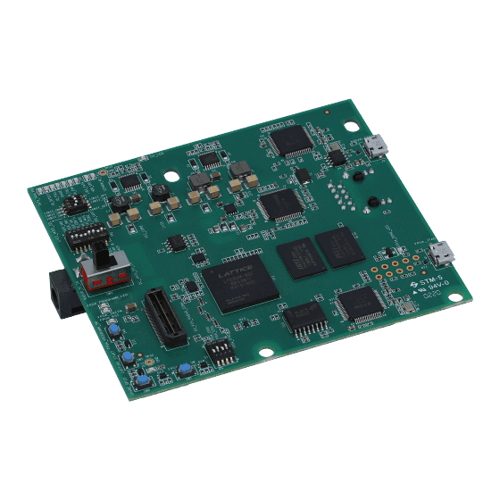
Page 5: Dca1000Evm - Top View
Hardware Specifications www.ti.com Board Dimensions The DCA1000EVM dimensions are 90 mm × 102 mm × 1.6 mm. It is a 10-layer board fabricated with epoxy fiberglass FR4 grade material (UL94V-0 Certified). Figure 2. DCA1000EVM – Top View Figure 3. DCA1000EVM – Bottom View SPRUIJ4A –... -
Page 6: Dca1000Evm And Xwr1Xxx Evm Board Alignment
To enable easy measurements on the sensing objects on the horizontal plane, the xWR1xxx EVM (AWR1243BOOST/AWR1443BOOST/AWR1642BOOST) and DCA1000EVM can be mounted vertically by fixing the L-brackets. The following steps illustrate the assembly of the L-brackets, DCA1000EVM, and xWR1xxx EVM. 1. Align the DCA1000EVM and xWR1xxx EVM boards, as shown in Figure Figure 4. -
Page 7: Connect Boards
Hardware Specifications www.ti.com 3. Connect the DCA1000EVM with the xWR1xxx EVM, as shown in Figure Figure 6. Connect Boards 4. Connect the Samtec ribbon cable, as shown in Figure 7 Figure Figure 7. Connect Ribbon Cable SPRUIJ4A – May 2018 – Revised May 2019... -
Page 8: Connect Ribbon Cable (Side)
Figure 8. Connect Ribbon Cable (Side) Power Connections The DCA1000EVM is powered by 5-V power, either from a DC jack as shown in Figure 9, or from a 60-pin high density connector of TI's xWR1xxx EVM mated to J3 of DCA1000EVM, as shown in Figure 14. -
Page 9: J1 Usb Connector
USB Data Signal Positive Ground Ground Figure 11. J1 USB Connector To configure the FPGA through JTAG, connect a micro USB cable to J4 on the DCA1000EVM. SPRUIJ4A – May 2018 – Revised May 2019 DCA1000EVM Data Capture Card Submit Documentation Feedback... -
Page 10: J4 Usb Connector
2.5.2 Ethernet Jack The DCA1000EVM supports a Gigabit Ethernet port to provide the connection to the network. The Ethernet port is interfaced to the LATTICE FPGA through the Ethernet PHY DP83867IRPAPT, and is used to stream the captured data over the network to the host PC. -
Page 11: J6 Ethernet Jack
2.5.3 60-Pin High Density (HD) Connector The DCA1000EVM supports a 60-pin HD connector to interface with the xWR1xxx EVM. This connector provides the high-speed LVDS data, control signals (UART, SPI, I2C, RESET), and DMM interface signals. The DCA1000EVM captures data from the xWR1xxx EVM over a 4-lane LVDS interface and playbacks the data from the host PC to the xWR1xxx EVM over a 16-bit DMM/trace interface through the 60-pin connector. -
Page 12: J3 High Density Interface Connector
LVDS data pair 0 negative MCU_RSTn Reset input to xWR1xxx EVM Ground Figure 14. J3 High Density Interface Connector DCA1000EVM Data Capture Card SPRUIJ4A – May 2018 – Revised May 2019 Submit Documentation Feedback Copyright © 2018–2019, Texas Instruments Incorporated... -
Page 13: Mode Configuration_1
Ethernet. In software configuration mode, hardware DIP settings are ignored. When the DCA1000EVM is configured in hardware switch configuration mode, use the following switch settings for different modes of data capture. Table 7. Switch1 Functionality Information... -
Page 14: Mode Configuration_2
Future use SW2.8 USER_SW3 Future use Figure 16. Mode Configuration_2 2.6.2 Push Buttons The DCA1000EVM supports four push buttons for FPGA reset, data capture start, and other basic functions listed in Table Table 9. Push Button Functionality Information Reference Usage Description... -
Page 15: User Leds
This LED indicates the progress of data transfer, either Green through the network or saving into the SD card. SD_DETECT_LED5 When the SD card is mounted into the DCA1000EVM, this Green LED indicates whether the SD card is detected or not. SD_FULL_LED0 This LED indicates the full condition of the SD card. -
Page 16: System Setup
Figure 19. Board Setup Prerequisites • The DCA1000EVM should be connected to the host PC through an Ethernet cable for the data transfer process. • The DCA1000EVM should be connected to a PC through a USB cable (J1-Radar FTDI) for configuring the xWR1xxx EVM if the mmWave Studio is used to configure the radar device. -
Page 17: Dca1000Evm Ethernet Configuration Data
When SW2 is positioned at 6 (pin6), the DCA1000EVM loads the Ethernet configuration data from EEPROM. • In general, the EEPROM is blank when the DCA1000EVM comes out of the factory. The EEPROM remains blank until the updated EEPROM command is given to the DCA1000EVM through the Ethernet port. -
Page 18: Dca1000Evm Command And Data Format
DCA1000EVM Command and Data Format The DCA1000EVM follows UDP protocol and supports 14 predefined commands. The configuration and status of the DCA1000EVM are communicated through the configuration port. The data port is used to transfer raw mode/data separated mode data. - Page 19 0xEEAA Stop bits of packet. DCA1000EVM Data Format The DCA1000EVM sends raw mode/data separated mode data to the host through the data port. • Raw mode data format: the DCA1000EVM sends raw mode data in the following format. • Data separated mode data format: the DCA1000EVM sends data separated mode data in the following format.
-
Page 20: Use Case: Lvds Over Ethernet Streaming
DCA1000EVM Command and Data Format www.ti.com Stored File Format Raw mode data format: in raw mode, the file is stored in the following format: • Without sequence number: • With sequence number: Data separated mode data format: in data separated mode, the file is stored in the following format: •... -
Page 21: Errors
Change the Ethernet packet delay options to packets or receive jumbled packets from the avoid out of sequence. When increasing DCA1000EVM.This may be due to either Ethernet packet delay, streaming throughput is Ethernet fast streaming, UDP protocol, host PC decreased due to slower data capturing. -
Page 22: Troubleshooting
Troubleshooting www.ti.com Troubleshooting • To confirm Ethernet connectivity between the DCA1000EVM and host PC, use the Wireshark tool to check the Ethernet packet transfer. • Ensure that UDP is enabled in the host PC for UDP data transmission and reception. -
Page 23: Device Manager
FPGA boots up. By default, the FPGA image for data capture would already be flashed in DCA1000EVM. The user must only perform this step if they need to update to a newer version of image, or re-flash the image due to some issues. -
Page 24: Ftdi Usb Cable Detection
4. Click the Operation tab, and select the Access mode options as JTAG 1532 mode; and for Operation select “Erase Only” for the Erase bit file in the FPGA, as shown in Figure DCA1000EVM Data Capture Card SPRUIJ4A – May 2018 – Revised May 2019 Submit Documentation Feedback Copyright © 2018–2019, Texas Instruments Incorporated... -
Page 25: Select Jtag Option And Bit File
(xx -> Version No, yy -> Release Date). d. Select SPI Flash device as (Family: SPI Serial Flash, Vendor: Micron, Device: SPI-N25Q128A, Package: 16-pin SO16) SPRUIJ4A – May 2018 – Revised May 2019 DCA1000EVM Data Capture Card Submit Documentation Feedback Copyright © 2018–2019, Texas Instruments Incorporated... -
Page 26: Limitations
The SD card storage and playback feature is not supported in this release. • The DCA1000EVM FPGA requires a minimum delay of 12 ms between the bit clock starts and the actual LVDS data start to lock the LVDS PLL IP. - Page 27 NOTE: Page numbers for previous revisions may differ from page numbers in the current version. Changes from Original (May 2018) to A Revision ......................Page .................. • Updated DCA1000EVM Functional Block Diagram................• Updated FPGA - SPI Flash Programming Mode section. SPRUIJ4A – May 2018 – Revised May 2019 Revision History Submit Documentation Feedback Copyright ©...
- Page 28 TI products. TI’s provision of these resources does not expand or otherwise alter TI’s applicable warranties or warranty disclaimers for TI products. Mailing Address: Texas Instruments, Post Office Box 655303, Dallas, Texas 75265 Copyright © 2019, Texas Instruments Incorporated...
Need help?
Do you have a question about the DCA1000EVM and is the answer not in the manual?
Questions and answers