
Related Manuals for Eaton Cutler-Hammer W-VAC


Summary of Contents for Eaton Cutler-Hammer W-VAC
- Page 1 Cutler-Hammer I.B. 3A74791H04 Instructions for Installation, Operation and Maintenance of Type W-VAC 36kV Vacuum Circuit Breakers Effective 7/97...
- Page 3 I.B. 3A74791H04 Page iii WARNING WARNING IMPROPERLY INSTALLING OR MAINTAINING THE CIRCUIT BREAKERS DESCRIBED IN THIS THESE PRODUCTS CAN RESULT IN DEATH, SERI- BOOK ARE DESIGNED AND TESTED TO OPERATE OUS PERSONAL INJURY, OR PROPERTY DAMAGE. WITHIN THEIR NAMEPLATE RATINGS. OPERATION OUTSIDE OF THESE RATINGS MAY CAUSE THE READ AND UNDERSTAND THESE INSTRUCTIONS EQUIPMENT TO FAIL, RESULTING IN DEATH, BOD-...
-
Page 4: Table Of Contents
I.B. 3A74791H04 Page iv TABLE OF CONTENTS Page SECTION 1: INTRODUCTION Preliminary Comments and Safety Precautions....................1 1-1.1 Warranty and Liability Information ......................1 1-1.2 Safety Precautions ..........................1 General Information.............................1 Type W-VAC Vacuum Circuit Breaker Ratings (Table 1.1).................2 Outlines and Dimensions ............................3 SECTION 2: SAFE PRACTICES Recommendations ..............................4... - Page 5 I.B. 3A74791H04 Page v Page 5-3.3 Closing Operation..........................20 5-3.4 Tripping Operation..........................20 Control Schemes...............................20 5-4.1 Timing..............................20 5-4.2 Secondary Disconnects........................23 5-4.3 Undervoltage Trip Device ........................23 Interlocks and Interfacing ..........................24 Levering Mechanism ............................24 Operations Counter ............................24 Ground Contact ..............................24 MOC and TOC Switch Operations ........................24 SECTION 6: INSPECTION, MAINTENANCE AND TROUBLESHOOTING Introduction................................26...
- Page 6 I.B. 3A74791H04 Page vi FIGURES Figure Title Page Type W-VAC 36kV Circuit Breaker Outlines and Dimensions..............3 Circuit Breaker Shown Mounted with Ramp Still in Shipping Position............5 Circuit Breaker Shown Being Moved Carefully Down Attached Ramp............6 Optional Fifth Wheel Shown in Use ......................6 Front View W-VAC 36kV Vacuum Circuit Breaker ..................8 W-VAC 36kV Vacuum Circuit Breaker with Front Cover Removed............9 Rear View W-VAC 36kV Vacuum Circuit Breaker ...................10...
-
Page 7: Preliminary Comments And Safety Precautions
I.B. 3A74791H04 Page 1 SECTION 1: INTRODUCTION EXAMPLE OF A TYPICAL WARNING LABEL HEAD- ING IS SHOWN ABOVE IN REVERSE TYPE TO FAMILIARIZE PERSONNEL WITH THE STYLE OF 1-1 PRELIMINARY COMMENTS AND SAFETY PRESENTATION. THIS WILL HELP TO INSURE PRECAUTIONS THAT PERSONNEL ARE ALERT TO WARNINGS, WHICH MAY APPEAR THROUGHOUT THE DOCU- This technical document is intended to cover most... -
Page 8: Type W-Vac Vacuum Circuit Breaker Ratings (Table 1.1)
I.B. 3A74791H04 Page 2 1-3 TYPE W-VAC VACUUM CIRCUIT BREAKER RATINGS (TABLE 1.1) EQUIPMENT TO FAIL, RESULTING IN DEATH, BODI- WARNING LY INJURY AND PROPERTY DAMAGE. ALL SAFETY CODES, SAFETY STANDARDS THE CIRCUIT BREAKERS DESCRIBED IN THIS AND/OR REGULATIONS AS THEY MAY BE APPLIED BOOK ARE DESIGNED AND TESTED TO OPERATE TO THIS TYPE OF EQUIPMENT MUST BE STRICTLY WITHIN THEIR NAMEPLATE RATINGS. -
Page 9: Outlines And Dimensions
I.B. 3A74791H04 Page 3 1-4 OUTLINES AND DIMENSIONS 908 REF OPEN/CLOSE M.O.C. OPERATOR FLOOR TRIPPERS SEE PLAN VIEW 16 MIN TRAVEL IN DIRECTION OF TO TRIP ARROW "X" DETAIL PLAN VIEW IN DIRECTION OF ARROW “X” 293 (TYP) CONTACT EROSION INDICATOR FLAG 1197 REF 1164... -
Page 10: Safe Practices
I.B. 3A74791H04 Page 4 SECTION 2: SAFE PRACTICES • Do not work on a drawout circuit breaker with a sec- ondary test coupler engaged. Failure to disconnect the test coupler could result in an electrical shock 2-1 RECOMMENDATIONS leading to death, personal injury or property damage. Type W-VAC Vacuum Circuit Breakers are equipped •... -
Page 11: Receiving, Handling And Storage
I.B. 3A74791H04 Page 5 SECTION 3: RECEIVING, HANDLING AND FOR OPENING, CLOSING THE CONTACTS OR CHARGING THE SPRINGS. THE CIRCUIT BREAKER STORAGE MAY SLIP OR FALL CAUSING SEVERE PERSONAL INJURY. ALWAYS PERFORM MAINTENANCE, 3-1 GENERAL REPAIR AND ADJUSTMENTS ON A SOLID WORK SURFACE CAPABLE OF SUPPORTING THE CIR- Type W-VAC Vacuum Circuit Breakers are subjected to CUIT BREAKER. -
Page 12: Storage
I.B. 3A74791H04 Page 6 AND UNDER CONTROL TO AVOID ANY ACCI- 3-4 STORAGE DENTS. THE CIRCUIT BREAKER IS A LARGE DEVICE WHICH COULD CAUSE SERIOUS BODILY If the circuit breaker is to be placed in storage, maxi- INJURY IF IT IS TIPPED OVER OR PERMITTED TO mum protection can be obtained by keeping it packed ROLL IN AN UNCONTROLLED MANNER. -
Page 13: Tools And Accessories
I.B. 3A74791H04 Page 7 3-6 TYPE W-VAC VACUUM CIRCUIT BREAKER check, leave the closing springs “discharged” and circuit breaker contacts “open”. WEIGHTS (TABLE 3.1) Outdoor storage is NOT recommended. If unavoidable, Table 3.1 W-VAC Circuit Breaker Weights the outdoor location must be well drained and a tempo- rary shelter from sun, rain, snow, corrosive fumes, dirt, Rating Pounds... -
Page 14: Front View W-Vac 36Kv Vacuum Circuit Breaker
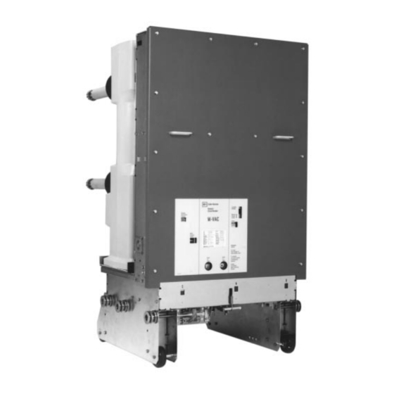
I.B. 3A74791H04 Page 8 Front Cover Lift/Pull Handle Contact Erosion Indicator Flags Circuit Breaker Wheel Secondary Contact Block Alignment Rollers Figure 3-4 Front View W-VAC 36kV Vacuum Circuit Breaker Effective 7/97... -
Page 15: W-Vac 36Kv Vacuum Circuit Breaker With Front Cover Removed
I.B. 3A74791H04 Page 9 L.H. Closing Spring Shock Absorber Motor Cutoff Switch Shunt Trip Assembly R.H. Closing Spring Spring Release (Close Coil) Assembly Opening Spring Closing Cam Manual Charge Socket Open/Close Indicator Ratchet Wheel Operations Counter Charging Motor Figure 3-5 W-VAC 36kV Vacuum Circuit Breaker with Front Cover Removed Effective 7/97... -
Page 16: Rear View W-Vac 36Kv Vacuum Circuit Breaker
I.B. 3A74791H04 Page 10 Pole Unit Primary Disconnect Insulation Shroud Opening to View Contact Erosion Mark Circuit Breaker Wheel Alignment Rollers TOC Operator Figure 3-6 Rear View W-VAC 36kV Vacuum Circuit Breaker Effective 7/97... -
Page 17: Typical W-Vac 36Kv Escutcheon
I.B. 3A74791H04 Page 11 Manual Charge Socket Spring Charged/Discharged Indicator Rating Nameplate Manual Open Button Manual Close Button Open/Close Indicator Operations Counter Figure 3-7 Typical W-VAC 36kV Escutcheon Effective 7/97... -
Page 18: Initial Inspection And Installation
I.B. 3A74791H04 Page 12 SECTION 4: INITIAL INSPECTION AND 4-4 INSULATION INSTALLATION Check the circuit breaker’s primary and secondary insu- lation as described in Section 6. 4-1 INTRODUCTION 4-5 CONTACT EROSION AND WIPE WARNING Manually charge the closing springs and close the cir- BEFORE PLACING THE CIRCUIT BREAKER IN SER- cuit breaker. -
Page 19: Electrical Operation Check
I.B. 3A74791H04 Page 13 is the DISCONNECT position. Without moving the cir- 4-8 ELECTRICAL OPERATION CHECK cuit breaker, manually engaging the secondary contacts now makes this the TEST position. After having completed all previous checks and tests, the circuit breaker is ready to be operated electrically. It To engage the secondary contacts, grasp the structure is preferred that this check be made with the circuit mounted secondary disconnect cage handle located... -
Page 20: 4-8.2 Operation Check Performance
I.B. 3A74791H04 Page 14 4-8.2 OPERATION CHECK PERFORMANCE 4-9.2 INTERFACING CHECK Move the circuit breaker to the TEST position and Keep in mind that an interfacing check will be made with engage the secondary contacts following the procedure a compatible structure. As such, the instructions provid- described in Paragraph 4-8.1. - Page 21 I.B. 3A74791H04 Page 15 Secondary Disconnect Plug Trip Floor Tripper Close Floor Tripper MOC Operator Figure 4-2 Type W-VAC Circuit Breaker (Bottom View) Effective 7/97...
-
Page 22: Description And Operation
I.B. 3A74791H04 Page 16 SECTION 5: DESCRIPTION AND This section describes the overall operation of the circuit breaker as well as the function and operation of all OPERATION major sub-assemblies and/or parts. 5-1 INTRODUCTION 5-2 INTERRUPTER ASSEMBLY The Type W-VAC 36kV Vacuum Circuit Breaker is a horizontal drawout roll on the floor design for use in new The W-VAC 36kV design utilizes three individually switchgear, as well as for modernization and life exten-... -
Page 23: 5-2.1 Vacuum Interrupter
I.B. 3A74791H04 Page 17 CAUTION THE PLATE BOLTED TO THE REAR RECTANGU- Shield Involvement Interruption LAR OPENING ON ALL 2000 AMPERE AND ABOVE Current CIRCUIT BREAKERS AND IDENTIFIED IN FIGURE 5- High Current Initiation Zero 2 MUST BE BOLTED IN POSITION BEFORE PLAC- Arc Mode ING A CIRCUIT BREAKER IN SERVICE TO INSURE Fault... -
Page 24: 5-2.3 Loading Spring Indication
I.B. 3A74791H04 Page 18 mark is located on the insulated operating rod of each ALL SUCH ADJUSTMENTS ARE FACTORY SET interrupter (Figures 6-2 and 6-3). AND SHOULD NOT BE ATTEMPTED IN THE FIELD. A second more convenient indicator is located on the front of the circuit breaker (Figure 3-4). -
Page 25: Closing Cam And Trip Linkage
I.B. 3A74791H04 Page 19 Figure 5-4a Breaker open Figure 5-4b Breaker open and closing spring discharged and closing spring charged Figure 5-4d Breaker closed Figure 5-4c Breaker closed and closing spring charged and closing spring discharged Cam Shaft Main Link Roller Pole Shaft Closing Cam Main Link... -
Page 26: 5-3.3 Closing Operation
I.B. 3A74791H04 Page 20 rotate the closing spring cranks and the closing cam 5-3.4 TRIPPING OPERATION with it. When the trip “D” shaft is turned either by the trip button The closing spring cranks have spring ends connected or trip coil, all links return to the original “open” condition to them, which are in turn coupled to the closing springs. -
Page 27: Charging Schematic
I.B. 3A74791H04 Page 21 Breaker Closed, Springs Charged Breaker Open, Springs Discharged Pole Shaft Cam Shaft Anti-Close Interlock Motor Ratchet Lever Spring Release (Close) Latch Drive Pawl Spring Crank Ratchet Wheel Closing Spring Holding Pawl Closing Spring Fixed End Spring Release (Close) Clapper Spring Release (Close) Coil Spring Release Latch (Close Roller) Figure 5-5 Charging Schematic... -
Page 28: Typical 36Kv W-Vac "Dc" And "Ac" Control Schematics
I.B. 3A74791H04 Page 22 BREAKER DC CONTROL SCHEMATIC SPRING CHARGED INDICATING LIGHT AUXILIARY SWITCH #2 OPTIONAL OPTIONS 18 17 CUSTOMER MUST FURNISH THIS “a” CONTACT FROM AUXILIARY SWITCH WHEN SECOND TRIP COIL OPTION IS CHOSEN AND MAKE THE APPROPRIATE CONNECTIONS. BREAKER AC CONTROL SCHEMATIC SPRING CHARGED... -
Page 29: 5-4.2 Secondary Disconnects
I.B. 3A74791H04 Page 23 5-4.2 SECONDARY DISCONNECTS coil. The circuit breaker can be closed as long as the voltage to the trip coil is maintained at 85% or above the The circuit breaker control wiring is arranged to connect rated level. The undervoltage trip device is available a standard 24 point male plug with a corresponding only as an instantaneous type with rated voltages of switchgear compartment mounted female plug. -
Page 30: Interlocks And Interfacing
I.B. 3A74791H04 Page 24 4. As the circuit breaker opens, the reset lever (8) con- 5-7 OPERATIONS COUNTER nected to the pole shaft lever (7) operates to reset the moving clapper. As long as the circuit breaker All circuit breakers are equipped with a mechanical remains open, the reset lever holds down the moving operations counter. -
Page 31: Undervoltage Trip Device Configuration
I.B. 3A74791H04 Page 25 Moving Clapper Trip D Shaft Lever Stationary Yoke Slotted Link UV Trip Device Coil Pole Shaft Lever Extension Springs Reset Lever Figure 5-8 Undervoltage Trip Device Configuration Effective 7/97... -
Page 32: Inspection, Maintenance And Troubleshooting
I.B. 3A74791H04 Page 26 SECTION 6: INSPECTION, MAINTENANCE 4. Follow the steps presented in Paragraph 6-3 entitled “Inspection and Maintenance Procedures” for sched- AND TROUBLESHOOTING uled programs. 6-1 INTRODUCTION 5. Create and maintain a dated permanent record of all inspections, maintenance performed, actions taken, observations made, and measurements taken. -
Page 33: Torque Guidelines
I.B. 3A74791H04 Page 27 should be applied in conjunction with the experience Table 6.1 Torque Guidelines and good judgment of the individual performing the work. Bolt Size Torque (N•M) 8 - 32 WARNING 10 - 32 1/4 - 20 OVER TORQUING CAN CAUSE PERMANENT DAM- AGE WHILE UNDER TORQUING WILL NOT PRO- 5/16 - 18 VIDE THE PROPER CLAMPING FORCE AND MAY... -
Page 34: Lubrication Points
I.B. 3A74791H04 Page 28 Apply one drop of light machine oil such as Mobil One at locations shown. Figure 6-1 Lubrication Points Effective 7/97... -
Page 35: Inspection And Maintenance Procedures
I.B. 3A74791H04 Page 29 6-3 INSPECTION AND MAINTENANCE PROCEDURES No./Section Inspection Item Criteria Inspection Method Corrective Action 1. Insulation Drive Insulator No dirt Visual Check Clean with lint-free cloth Molded Pole Unit Support No cracking Visual Check Replace cracked unit Insulation Main Circuit to Ground Withstand... -
Page 36: Vacuum Interrupter Integrity Test
I.B. 3A74791H04 Page 30 6-4 VACUUM INTERRUPTER INTEGRITY TEST Although an ac high potential test is recommended, a dc test may be performed if only a dc test unit is available. Vacuum interrupters used in Type W-VAC 36kV Vac- In this case the equipment must be capable of delivering uum Circuit Breakers are highly reliable interrupting ele- 5 milliamperes for one minute to avoid ambiguity due to ments. -
Page 37: Insulation
I.B. 3A74791H04 Page 31 Base of Interrupter Standard 300mm Metal Scale Millimeter Measurement Line Figure 6-2 Rear Measurement for Contact Erosion Being Made (Circuit Breaker Closed) Figure 6-3 Graphical Representation of Contact Erosion Measurement (Circuit Breaker Closed) 6-7 INSULATION breaker. For circuit breakers rated 36kV the test voltage is 60kV rms. -
Page 38: Primary Circuit Resistance Check
I.B. 3A74791H04 Page 32 CONTACT WIPE Figure 6-4 Side View of Loading Spring Indicator (Circuit Breaker Closed) 6-9 PRIMARY CIRCUIT RESISTANCE CHECK Figure 6-5 Graphical Representation of Contact Wipe Since the main contacts are inside the vacuum cham- Measurement of Loading Spring Indicator (Circuit ber, they remain clean and require no maintenance at Breaker Closed) any time. -
Page 39: Troubleshooting Chart
I.B. 3A74791H04 Page 33 Table 6.3 Typical Resistance Measurements is definite evidence of sluggishness, dirt or parts are dis- mantled for some reason. Rated Continuous Resistance If it becomes necessary to disassemble the mechanism, Current (amperes) (microohms) the bearings and related parts should be thoroughly cleaned. - Page 40 I.B. 3A74791H04 Page 34 6-12 TROUBLESHOOTING CHART (Continued Next Page) SYMPTOM INSPECTION AREA PROBABLE DEFECTS Fails To Close • Closing Spring charged but • No Closing Sound • Control Power circuit breaker does not close (Close Coil does (Fuse blown or switch off) not pick up) •...
- Page 41 I.B. 3A74791H04 Page 35 6-12 TROUBLESHOOTING CHART SYMPTOM INSPECTION AREA PROBABLE DEFECTS Undesirably Closes • Control Circuit • Close Circuit (CS/C Getting Shorted) • Mechanism • Close Release Latch (Fails to reset) • Close Floor Tripper (Fails to reset) Fails To Trip •...
-
Page 42: Renewal Parts
I.B. 3A74791H04 Page 36 SECTION 7: RENEWAL PARTS 7-1.1 ORDERING INSTRUCTIONS a. Always specify the breaker rating information and 7-1 GENERAL shop order number. b. Describe the item, give the style number, and specify In order to minimize production downtime, it is recom- the quantity required. - Page 43 I.B. 3A74791H04 Page 37 7.1 Recommended Renewal Parts for ANSI Rated Breakers (Continued Next Page) LINE DESCRIPTION STYLE NUMBER VCP-W 360/25, 630A - 25kA 3A74813H01 360/25, 1250A - 25kA 3A74814H01 360/25, 1600A - 25kA 3A74815H01 360/25, 2000A - 25kA 3A74816H01 360/32, 630A - 31.5kA 3A74819H01 360/32, 1250A - 31.5kA...
- Page 44 I.B. 3A74791H04 Page 38 7.1 Recommended Renewal Parts for ANSI Rated Breakers (Continued Next Page) VCP-W Spring Release Coils 48VDC 3759A76G11 125VDC/120VAC 3759A76G12 250VDC/240VAC 3759A76G13 Rectifier (120/240VAC) 3759A76G02 Anti Pump (Y) Relay 48VDC 8237A27H03 125VDC 8237A27H04 250VDC 8237A27H05 120VAC 8237A27H01 240VAC 8237A27H02 Shunt Trip Coils...
- Page 45 I.B. 3A74791H04 Page 39 7.1 Recommended Renewal Parts for ANSI Rated Breakers (Continued Next Page) VCP-W Motor Cutoff Switch 699B199G04 Latch Check Switch 699B147H04 Position Switch 699B147H01 Position Switch 3759A93H02 Auxiliary Switch 5697B20H01 Trip D-Shaft 694C638G01 Trip Latch (Hatchet) 699B040G03 LINE DESCRIPTION STYLE NUMBER...
- Page 46 I.B. 3A74791H04 Page 40 7.1 Recommended Renewal Parts for ANSI Rated Breakers (Continued Next Page) VCP-W Ground Contact Assy. 16kA 8796C85G01 25kA 8796C85G02 31.5kA 8796C85G03 21/35kA 8796C85G04 Shock Absorber 5677B26H01 Front Panel (w/o ESCN) 4D13655H02 Breaker Rail Wheel 5680B22G01 Shutter Drive Roller 5680B24H02 Breaker Floor Wheel 3A74342H01...
- Page 47 I.B. 3A74791H04 Page 41 7.1 Recommended Renewal Parts for ANSI Rated Breakers VCP-W Fastener Kit 8061A01G01 Closed Open Labels Kit 8295A45G02 Discharged Charged Wiring Harness Repair Kit 8796C82G01 Complete Replacement 8796C82G02 With #2 AUX SW 8798C82G03 Undervoltage Kit 48VDC 8794C81G01 125VDC 8794C81G02 250VDC...
- Page 48 I.B. 3A74791H04 This instruction booklet is published solely for informa- tion purposes and should not be considered all inclu- sive. If further information is required, you should con- sult Cutler-Hammer. Sale of product shown in this literature is subject to terms and conditions outlined in appropriate Cutler- Hammer selling policies or other contractual agreement between the parties.
Need help?
Do you have a question about the Cutler-Hammer W-VAC and is the answer not in the manual?
Questions and answers