
Related Manuals for Bender ISOMETER IR1575H


Summary of Contents for Bender ISOMETER IR1575H
- Page 1 ISOMETER® IR1575H Insulation monitoring device for IT AC and DC systems Software version: D0275 V1.3 IR1575H_D00416_00_M_XXEN / 03.2021 Manual EN...
- Page 2 Service and support for Bender products First-level support Technical support Carl-Benz-Strasse 8 • 35305 Grünberg • Germany Telephone: +49 6401 807-760 0700BenderHelp * Fax: +49 6401 807-629 E-mail: support@bender-service.de Available on 365 days from 7.00 a.m. to 8.00 p.m. (MEZ/UTC +1) * Landline German Telekom: Mon-Fri from 9.00 a.m.
-
Page 3: Table Of Contents
ISOMETER® IR1575H Table of Contents Safety information ................5 Intended use ........................5 Warranty and liability....................5 1.2.1 Personnel ..........................5 1.2.2 Hazards when handling the ISOMETER® ..............6 1.2.3 Inspection, transport and storage ...................6 1.2.4 Note ............................6 Explanation of symbols and warnings ..............6 Directions for installation ...................7 Function ....................8 Features ..........................8 Product description ......................8... - Page 4 IR1575H_D00416_00_M_XXEN / 03.2021...
-
Page 5: Safety Information
ISOMETER® IR1575H Safety information Intended use The ISOMETER® is intended for: • monitoring the insulation resistance of IT systems Any other use, or use which goes beyond the foregoing, is deemed to be use other than for the intended purpose. Use for the intended purpose also includes: •... -
Page 6: Hazards When Handling The Isometer
In the event of damage in transit, please inform the Bender company immediately. The devices must only be stored in areas protected from dust, damp and spray or dripping water, and in which the specified storage temperatures are maintai- ned. -
Page 7: Directions For Installation
ISOMETER® IR1575H Directions for installation CAUTION! Ensure disconnection from the IT system! Only one insulation monitoring device may be used in each interconnected IT system. When insulation or voltage tests are to be carried out, the device must be isolated from the sys- tem for the test period. -
Page 8: Function
(AMP measuring principle). The „adaptive measuring pulse“, is a measu- ring method developed and patented by Bender (European Patent: EP 0 654 673 B1). The measuring pulse consists of positive and negative cycles of the same amplitude. The period depends on the respective system leakage capacitances and the insulation resistance of the system to be monitored. -
Page 9: Self Test
2. Press the TEST button. earth (PE). 3. Switch the supply voltage off and on. Device error x Internal device error 4. Press the TEST button. 5. Switch the supply voltage off and on. 6. Please contact Bender. IR1575H_D00416_00_M_XXEN / 03.2021... - Page 10 Function Reset run control If, for operational reasons, the supply voltage cannot be switched on and off, a reset of the run control can be carried out by pressing the buttons RESET, MENU and TEST sequentially. Proceed as follows: 1. Press and hold down the RESET button. 2.
-
Page 11: Commissioning Flow Chart
ISOMETER® IR1575H Commissioning flow chart In the three-page commissioning flow chart, the encircled numbers correspond to the numbers in the legend to wiring diagram (see page 14). A0/A1 or A0/A2. technical data. to Commissioning (2) IR1575H_D00416_00_M_XXEN / 03.2021... - Page 12 Commissioning flow chart Commissioning of the ISOMETER® (2) Connect the supply voltage The A-ISOMETER carries out a self test. The display indicates Connect the voltage of the the insulation value after finishing system to be monitored the measurement. Shall the basic setting be changed? Select ISO SETUP Alarm1 = 40 kOhm...
- Page 13 ISOMETER® IR1575H Commissioning of the ISOMETER® (3) In order to check the proper connection, a functional test using a suitable resistor is to be carried out. Size of the resistance: 50% of the preset response value Alarm 2. Check the connecting leads ! Do both alarm LEDs light up? Is voltage Un applied to the Did the alarm relays switch ?
-
Page 14: Connection
Connection Connection The ISOMETER® provides plug-in terminals. The connections A0/A1 resp. A0/A2 to the supply voltage U have to be provided with protective devices according to IEC 60364-4-43. A 6 A fuse is recommended. Devices for protection against short-circuit in conformity with IEC 60364-4-43 for the coupling of terminals L1/L2 to the IT system being monitored can be omitted if the wiring is carried out in such a manner as to reduce the risk of a short-circuit to a minimum. -
Page 15: Operation And Setting
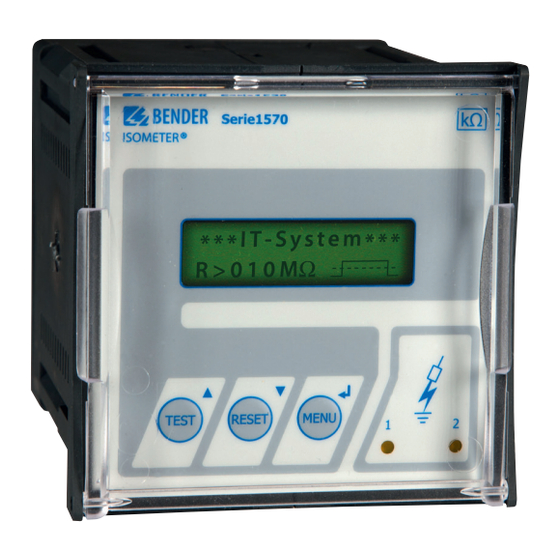
ISOMETER® IR1575H Operation and setting Diplay and operating elements Legend Two-line display for standard and menu mode * * * I T - S Y S T E M * * * * TEST button: to call up the self test R >... -
Page 16: Function Keys
Operation and setting 5.1.3 Function keys Two functions are assigned to each function key. In addition to the basic function marked with a circle, the keys allow navigation within the menu. Meaning Press the TEST key to start the self test of the ISOMETER® Press the RESET key to reset insulation fault alarms stored in the TEST RESET... -
Page 17: Menu Structure And Menu Mode
ISOMETER® IR1575H Menu structure and menu mode To switch to the menu mode Press the MENU key to switch from the standard mode to the menu mode and to the main menu. From here you can branch to the different submenus. Navigation within the menu Use the UP and DOWN keys to select the appropriate menu item. - Page 18 2. Password: XXX Password: XXX 3. Status: off 1. Exit 1. Exit 1. Exit 2. Alarm1 040 kW 2. Text: Deutsch BENDER GRUENBERG 3. Alarm2 010 kW IR1575H 4. K1 : N.O ---FIRMWARE--- 5. K2 : N.O D275 V1.3 6. Memory: off...
-
Page 19: Menu Iso Setup: Setting Of The Isometer® Functions
ISOMETER® IR1575H Menu ISO SETUP: Setting of the ISOMETER® functions All alarm functions such as Alarm1 and Alarm2 (prewarning and alarm), the operating principle of the alarm relays K1 and K2 (N.O = N/O operation, N.C = N/C operation) and the fault memory behaviour are set in this menu. -
Page 20: Memory Setting (On/Off)
Operation and setting ISO SETUP diagram *** IT-SYSTEM *** R >5.0 MW 1. EXIT 2. ISO SETUP 3. PASSWORD 4. LANGUAGE 5. SERVICE 6. INFO 1. Exit 2. Alarm1: 100 KW Alarm1 : 100 KW 3. Alarm2: 200 KW 4. K1 : N.O 2 KW .. -
Page 21: Password Menu
ISOMETER® IR1575H PASSWORD menu The „Password“ query can be activated in this menu. This protects the ISOMETER® against unauthorized settings and modifications. Use the arrow keys to select the desired password (menu item 2. password: xxx) and confirm with ENTER to finish the action. Select the menu item „3. -
Page 22: Language Menu
Operation and setting LANGUAGE Menu Use this menu item to set the language for the fault messages.You have the choice between German and English. All the device menus are displayed in English, irrespective of the selected language. Language diagram *** IT-SYSTEM *** R >5.0 MW 1. -
Page 23: Service Menu
ISOMETER® IR1575H SERVICE menu This menu item is provided for the Bender service personnel and protected by a password against erroneous settings. It is intended to provide fast fault clearance by qualified experts in the event of a device error. -
Page 24: Technical Data Ir1575H
Technical data IR1575H Technical data IR1575H Data in tabular form Insulation coordination acc. to IEC 60664-1 Rated insulation voltage ............................. AC 800 V Rated impulse voltage/pollution degree ........................8 kV/3 Voltage ranges Nominal system voltage U ........................1AC/3(N)AC 0…793 V Nominal frequency f ............................ - Page 25 ISOMETER® IR1575H Outputs/Inputs TEST/RESET button ............................internal/external Max. cable length TEST/RESET button external ........................ 10 m Switching elements Switching elements ..........................2 changeover contacts Operating principle ..........................N/O or N/C operation Factory setting (Alarm1/Alarm2) ........................N/O operation Electrical endurance, number of cycles ...........................12 000 Contact class ............................
-
Page 26: Standards And Certifications
Technical data IR1575H Standards and certifications The ISOMETER® was designed under consideration of the following standards: • EN 60664-1 • EN 61326-2-4 • EN 61557-1 • EN 61557-8 Characteristic curves ISOMETER® response times in relation to system leakage capacitances: = 1…100 µF, U = 0…793 V/50 Hz 1000 ≤... -
Page 27: Dimension Diagram Enclosure Ir1575H
ISOMETER® IR1575H Dimension diagram enclosure IR1575H 96,5 mm ca. 120 mm 17,6 designed for panel mounting. The required knock-outs are illustrated in the figure below: 92 mm + 0,8 / - 0 IR1575H_D00416_00_M_XXEN / 03.2021... - Page 28 Nachdruck und Vervielfältigung Reprinting and duplicating nur mit Genehmigung des Herausgebers. only with permission of the publisher. Bender GmbH & Co. KG Bender GmbH & Co. KG Postfach 1161 • 35301 Grünberg • Deutschland PO Box 1161 • 35301 Grünberg • Germany Londorfer Str.
Need help?
Do you have a question about the ISOMETER IR1575H and is the answer not in the manual?
Questions and answers