Table of Contents
Advertisement
Quick Links
Advertisement
Table of Contents

Related Manuals for Tech Controllers L-7


Summary of Contents for Tech Controllers L-7
- Page 1 user’s manual user’s manual www.tech-controllers.com...
- Page 2 User’s manual...
-
Page 3: Table Of Contents
Table of contents Safety Description of the device II.a) Principle of operation III. Installation III.a) First start-up Main screen view and description Controller function V.a) Block diagram of the main menu V.b) Screen view V.c) Manual operation V.d) Zones V.e) Pump V.f) Language... -
Page 4: Safety
User’s manual I. Safety Before using the device for the fi rst time the user should read the following regulations carefully. Not obeying the rules included in this manual may lead to personal injuries or controller damage. The user’s manual should be stored in a safe place for further reference. -
Page 5: Description Of The Device
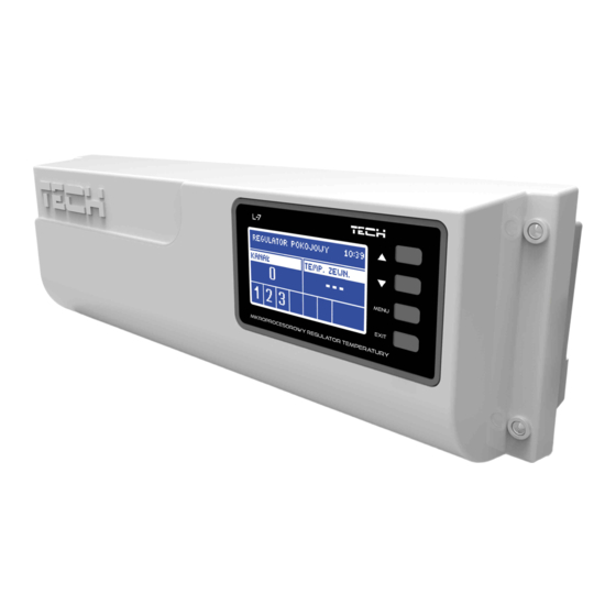
Controller dimensions II.a) Principle of operation L-7 controller decides if a given zone needs to be heated on the basis of current temperature value sent by the room sensor (C-7p) as well as the individual operation algorithm of the zone. -
Page 6: Installation
1. Cover (it should be removed to connect the devices to be controlled) 2. Display 3. Buttons L-7 controller may be installed as a free-standing device or as a panel mountable on a wall. The controller may be installed on a DIN strip... -
Page 7: Iii.a) First Start-Up
In order for the controller to operate correctly, the user must follow these steps when starting the device for the fi rst time: 1. Connect L-7 with all the subordinate devices to be controlled 2. Switch on the power supply and check if the devices work. - Page 8 User’s manual...
- Page 9 Pictorial diagram presenting wiring and communication with other devices in the system...
- Page 10 STEP 3: Activate the Internet module L-7 external controller is compatible with ST-507 and WiFi RS. WiFi RS uses WiFi wireless network whereas ST-507 needs to be connected to a router with RJ45 network cable.
- Page 11 Set current time and date in the fi tter’s menu. STEP 5. Confi gure the temperature sensors, room regulators TTo enable L-7 external controller to control a given zone, it is necessary to provide it with current temperature value. The easiest way is to use C-7p temperature sensor.
-
Page 12: Main Screen View And Description
User’s manual Main screen view and description The user navigates in the menu structure using the buttons located next to the display 1. Display 2. ▲- „up” „plus” – it is used to view the menu options and increase the value while editing parameters. - Page 13 11. An icon indicating pump operation 2. An icon indicating that the additional contact is switched on 3. Current time 4. Time left until the manually set temperature in a given zone changes 5. Information about the type of current weekly schedule 6.
-
Page 14: Controller Function
User’s manual Controller function Due to multiple function fulfi lled by the controller, the menu is divided into Main menu and Fitter’s menu. V.a) Block diagram of the main menu V.b) Screen view • In this submenu the user may adjust the main screen view: •... -
Page 15: V.c) Manual Operation
Submenu of each zone: V.d.1) OFF/ON After the room sensor has been connected and registered in a given zone, it is used by L-7 controller. The sensor may be deactivated by selecting OFF option. V.d.2) Pre-set temperature The pre-set zone temperature depends on the weekly schedule settings. -
Page 16: V.e) Pump
22,5⁰C. V.e) Pump L-7 controls the pump operation by activating it (after the delay time) if the temperature in any of the zones is too low. If the pre-set temperature of each zone is reached, the controller disables the pump. -
Page 17: V.h) Fitter's Menu
V.h.1) Valve L-7 external controller may also control an additional valve via a valve module (e.g. ST- 431N). The regulators communicate via RS communication but registration is necessary. There is a rage of parameters to confi gure the valve operation and adjust it to individual needs. - Page 18 User’s manual Weather-based control • For the function of weather control to be active, the external sensor mustn’t be exposed to sunlight or infl uenced by the weather conditions. After it is installed in an appropriate place and connected to the valve module, weather control function needs to be activated in the controller menu.
-
Page 19: V.i) Software Version
Internet. Such online control is possible only after purchasing and connecting an additional module ST-5072. The Internet module may be connected to L-7 via RS cable. After it has been connected, select Registration. The controller generates a code which the user should enter on the Internet website. -
Page 20: Protections And Alarms
User’s manual Protections and alarms In order to ensure safe and failure-free operation, the regulator has been equipped with a range of safeguards. In case of an alarm, a sound signal is activated and the display shows a message informing about the detected problem. Automatic sensor control In the event of temperature sensor or external sensor damage, an alarm is activated and the display shows an appropriate message, e.g.: „Alarm: no communication”. -
Page 21: Software Update
VII. Software update NOTE Software update shall be conducted only by a qualifi ed fi tter. After the software has been updated, it is not possible to restore previous settings. In order to install new software, the controller must be unplugged from the power supply. Next, insert the memory stick with the new software into the USB port. - Page 22 User’s manual EU Declaration of conformity no. 218/2016 Hereby, we declare under our sole responsibility that L-7 manufactured by TECH, headquartered in Wieprz Biała Droga 31, 34-122 Wieprz, is compliant with: • Directive 1999/5/EC of the European Parliament and of the Council of 9 March 1999...
- Page 24 TECH Spólka z ograniczoną odpowiedzialnością Sp.k. Biała Droga 31 34-122 Wiperz SERWIS 34-652 Bulowice ul. Skotnica 120 Tel.: +48 33 8759380, +48 33 3300018 +48 33 8751920, +48 33 8704700 Fax. +48 33 8454547 serwis@techsterowniki.pl Monday - Friday 7:00 - 16:00 Saturday 9:00 - 12:00 www.tech-controllers.com...
Need help?
Do you have a question about the L-7 and is the answer not in the manual?
Questions and answers