Table of Contents
Advertisement
Quick Links
Advertisement
Table of Contents

Related Manuals for Tech Controllers EU-2801 WiFi


Summary of Contents for Tech Controllers EU-2801 WiFi
- Page 1 EU- 2801 WiFi...
-
Page 2: Table Of Contents
TABLE OF CONTENTS SAFETY..................................4 DEVICE DESCRIPTION ..............................5 III. How to install ................................6 Main screen description ............................7 Controller menu................................. 8 Block diagram of main menu ............................ 8 WiFi module ................................9 Date and time ................................9 3.1. Clock settings .............................. - Page 3 10.4. Sensor calibration ............................14 Weekly control ..............................14 Language ................................14 Software version ..............................14 Service menu ..............................15 How to configure the module ..........................15 HOME TAB ................................16 USER MENU ................................. 16 SETTINGS TAB ..............................16 VII. Technical data ................................
-
Page 4: Safety
SAFETY Before using the device for the first time the user should read the following regulations carefully. Not obeying the rules included in this manual may lead to personal injuries or controller damage. The user’s manual should be stored in a safe place for further reference. -
Page 5: Device Description
Flush-mountable To the EU-2801 WiFi controller is attached room sensor C-mini. Such sensor is installed in particular heating zone. Is provide the main controller current room temperature reading. Room sensor should be registered in a particular zone. In order to do it, use <Registration>. Select <Registration> icon and press the communication button on a particular C-mini sensor. -
Page 6: How To Install
The controller should be installed by a qualified person. The device is intended to be installed on the wall. WARNING EU-2801 WiFi controller is intended to be installed in a flush-mounting box. It is powered with 230V/50Hz – the cable... -
Page 7: Main Screen Description
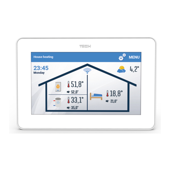
IV. MAIN SCREEN DESCRIPTION 1. Current CH boiler operation mode 2. Current time and day of the week – tap on this icon to set time and day of the week. 3. CH boiler icon: - flame in the CH boiler – CH boiler is active - no flame –... -
Page 8: Controller Menu
V. CONTROLLER MENU BLOCK DIAGRAM OF MAI N MENU WiFi network selection WiFi module Registration DHCP Module version Clock settins Date and time Date settings Automatic Heating Reduction Only DHW Mode Party Absent Holiday Screensaver Screen brightness Screen settings Screen blanking Blanking time Active on selected days Alarm clock settings... -
Page 9: Wifi Module
WIFI MODULE Internet module is a device enabling the user remote control of the heating system. The user controls the status of all heating system devices on a computer screen, a tablet or a mobile phone. After switching the module on and selecting DHCP option, the controller automatically downloads parameters from the local network. -
Page 10: Only Dhw
4.4. ONLY DHW The controller only supports the hot water circuit (heating circuit off) according to the settings <Temp. DHW> (set in the <Hot water> submenu) and Weekly settings. 4.5. PARTY The controller operates according to <Pre-set room temperature> parameter (in <Heating circuit> submenu) and <DHW temperature>... -
Page 11: Protections
PROTECTIONS This function enables the user to activate and deactivate the auto-lock. When auto-lock is active, it is necessary to enter PIN code in order to access the controller menu. NOTE Default PIN code is „0000”. HEATING CIRCUIT Constant Pre-set boiler temperature temperature* Type of control... - Page 12 The <Heating reduction> function - This parameter is connected with the Weekly schedule which enables the user to define the time periods for each day of the week when the CH boiler will operate based on the pre-set temperature settings. After activating the thermostat and setting the Heating reduction function at Decrease, the CH boiler will operate in two modes.
-
Page 13: Pre-Set Room Temperature
8.2. PRE-SET ROOM TEMPERATURE This parameter is used to define the pre-set room temperature (daytime comfort temperature). This parameter is used e.g. in the temporary program – it applies for the time specified in this program. 8.3. REDUCED PRE-SET ROOM TEMPRATURE This parameter is used to define the reduced pre-set room temperature (nighttime economical temperature). -
Page 14: Type Of Sensor
10.3. TYPE OF SENSOR The controller has a built-in sensor but is is also possible to use an additional wireless sensor. Such a sensor must be registered using one of the options: <Wireless sensor> or <Registration>. Next, press the communication button on the sensor within 30 seconds. -
Page 15: Service Menu
Once logged in, go to Settings tab and select Register module. Next, enter the code generated by the controller (to generate the code, select Registration in EU-2801 WiFi menu). The module may be assigned a name (in the are labelled Module description). -
Page 16: Home Tab
1. HOME TAB ome tab displays the main screen with tiles illustrating the current status of particular heating system devices. Tap on the tile to adjust the operation parameters Screenshot presenting an example tab with main menu parameters 2. USER MENU In the User menu it is possible to set the operating modes, boiler week and hot water and other parameters according to your needs. -
Page 17: Technical Data
Screenshot showing the tab Settings VII. TECHNICAL DATA Specification Value from 5°C to 40°C Range of room temperature setting 230V +/- 10% / 50Hz Supply voltage 1,3W Power consumption +/- 0,5°C Accuracy of room temperature measurement from 5°C to 50°C Operating temperature 868MHz Freuency... -
Page 18: Alarms
VIII. ALARMS EU-2801 WiFi room temperature regulator signalises all alarms which occur in the main controller. In case of alarm, the regulator activates a sound signal and the screen displays a message with error ID. NOTE In most cases, in order to remove an alarm it is necessary to delete it in the CH boiler controller. - Page 19 EU Declaration of conformity Hereby, we declare under our sole responsibility that EU-2801 WiFi manufactured by TECH STEROWNIKI, head- quartered in Wieprz Biała Droga 31, 34-122 Wieprz, is compliant with Directive 2014/53/EU of the European parliament and of the Council of 16 April 2014 on the harmonisation of the laws of the Member States relating to the making available...
Need help?
Do you have a question about the EU-2801 WiFi and is the answer not in the manual?
Questions and answers