Table of Contents
Advertisement
Quick Links
Advertisement
Table of Contents

Related Manuals for Tech Controllers ST-976


Summary of Contents for Tech Controllers ST-976
- Page 1 fwybór 1 ...
- Page 2 2 ...
-
Page 3: Table Of Contents
ABLE OF CONTENTS Safety ................................ 5 Device description ............................ 6 Installation .............................. 7 How to use the controller .......................... 9 Principle of operation......................... 10 4.1.1 Lambda sensor ........................... 10 Working phases of the controller ...................... 10 4.2.1 Fire‐up ............................ 10 4.2.2 Standard operation ........................ 10 4.2.3 Automatic operation ........................ 10 4.2.4 PID operation algorithm ...................... 11 4.2.5 Damping ............................. 11 Controller functions ‐ main menu ..................... 12 4.3.1 Fire‐up / Damping ........................ 13 4.3.2 ... - Page 4 4.4.7 Valve settings .......................... 27 4.4.8 Additional output 1, 2 ........................ 34 4.4.9 Room regulator .......................... 37 4.4.10 Fuel level calibration ........................ 38 4.4.11 Cleaning ............................ 39 4.4.12 Eco mode ............................ 39 4.4.13 Alarm history .......................... 41 4.4.14 Moduł GSM .......................... 41 4.4.15 Ethernet module ........................ 42 4.4.16 Factory settings .......................... 43 Protections .............................. 44 Thermal protection of the ch boiler .................... 44 Automatic sensor control ........................ 44 Thermal protection of the ch boiler (STB) .................. 44 Fuse .............................. 44 ...
-
Page 5: Safety
AFETY Before using the device for the first time the user should read the following regulations carefully. Not obeying the rules included in this manual may lead to personal injuries or controller damage. The user’s manual should be stored in a safe place for further reference. In order to avoid accidents and errors it should be ensured that every person using the device has familiarized themselves with the principle of operation as well as security functions of the controller. If the device is to be sold or put in a different place, make sure that the user’s manual is there with the device so that any potential user has access to essential information about the device. The manufacturer does not accept responsibility for any injuries or damage resulting from negligence; therefore, users are obliged to take the necessary safety measures listed in this manual to protect their lives and property. WARNING High voltage! Make sure the regulator is disconnected from the mains before performing any activities involving the power supply (plugging cables, installing the device etc.) The device should be installed by a qualified electrician. Before starting the controller, the user shoud measure earthing resistance of the electric motors as well as the insulation resistance of the cables. The regulator should not be operated by children. WARNING ... -
Page 6: Device Description
EVICE DESCRIPTION ST-976 controller is intended for controlling pellet‐fired CH boilers with a feeder, and a supply air fan. Due to advanced software, the controller offers a range of functions: Control of an igniter Control of a feeder Control of a burner‐cleaning grate Control of a supply air fan Control of an exhaust fan (after connecting an additional ST‐63 module) Control of central heating pump ‐ CH Control of domestic hot water pump ‐ DHW Smooth control of a mixing valve Control of additional pumps (max. 2) with the possibility of choosing the type of device (CH pump, DHW pump, circulating pump, floor pump, alarm) Built‐in module controlling the valve Weather‐based control of the valve Weekly control Cooperation with a room regulator using traditional (two‐state) or RS communication Manual burning option with automatic transition Possibility of monitoring the level of fuel in the tank Software update via USB ... -
Page 7: Installation
NSTALLATION The controller should be installed by a qualified person. WARNING Risk of fatal electric shock from touching live connections. Before working on the controller switch off the power supply and prevent it from being accidentally switched on. 7 ... - Page 8 Example installation schemes: 8. Room regulator 16. Additional sensor 2 1. CH pump 9. Flue gas sensor 17. Feeder sensor 2. DHW pump 10. CH sensor 18. Fire sensor 3. Additional pump 1 11. DHW sensor 19. Feeder 4. Valve 12. Valve sensor 20. Blow 5. Additional pump 2 13. Return sensor 6. External feeder 21. Ignite 14.
-
Page 9: How To Use The Controller
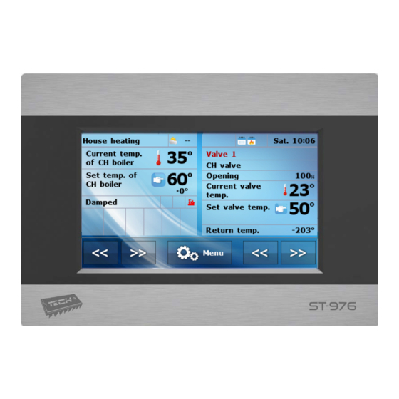
OW TO USE THE CONTROLLER The device is operated by means of a touch screen, in the bottom part of which there are navigation icons. The main screen is divided into two areas which may be adjusted to individual user’s needs using the arrows. The user may choose one of the following screen views: CH boiler temperature, CH boiler temperature chart, Water tank temperature, Water tank temperature chart, Fire‐up/Damping function, Fuel level, Parameters of built‐in valve. The upper left‐hand side of the screen displays current controller operation mode ‐ touch the screen here to change the operation mode. The right‐hand side of the screen displays current day of the week and time ‐ touch here to edit time settings. ... -
Page 10: Principle Of Operation
RINCIPLE OF OPERATION The regulator controls the fan and the feeder with the aim of reaching the pre‐set temperature value of water tank and CH boiler. Additionally, it controls CH pump and DHW pump, enabling them after the pre‐defined CH boiler temperature has been reached. Depending on the settings, the controller may operate according to standard algorithm, automatic algorithm or zPID algorithm. It may also use Lambda sensor. The menu layout may also differ depending on settings. 4.1.1 Lambda sensor Additionally, the controller operation may depend on LAMBDA sensor readings, which provide the information about the proportion of oxygen in the flue gas. On the basis of this value, the efficiency of the burning process is assessed. If the amount of oxygen is different than the pre‐set value, the regulator adjusts the fan speed as well as the amount of fuel fed to the boiler, in order to make the process more efficient. ORKING PHASES OF THE CONTROLLER Parameters of particular working phases of the CH boiler are configured by the user. Fire‐up and damping are multi‐stage processes described below. The remaining phases depend on the Operation algorithm selected by the user. 4.2.1 Fire‐up This phase is initialized by the user in the main menu, or by the controller software in certain situations (e.g. after periodical cleaning of the furnace during controller operation). There are four stages of the fire‐up process: 1. Blow‐by In this stage the fan works at full speed in order to clean the furnace. ... -
Page 11: Pid Operation Algorithm
4.2.4 PID operation algorithm If PID control function is active, the fan and feeder operation depend on current CH boiler temperature and the flue gas temperature. This type of controller calculates the blow force on the basis of CH boiler temperature and the flue gas temperature measured at the CH boiler outlet. The fan operates continuously and the blow force depends on the CH boiler temperature, the flue gas temperature as well as the difference between these parameters and their pre‐set values. One of the greatest advantages of PID regulators is their ability to maintain a stable pre‐ set temperature without unnecessary overregulation and oscillations. Using this type of regulator with a flue gas sensor helps to reduce fuel costs by up to several percent. Moreover, it ensures stable temperature of output water thus prolonging the life of the heat exchanger (of the CH boiler). Flue gas temperature control at the outlet results in low emission of dust and environmentally harmful gases. Flue gas heat is not disposed of through the chimney, but it is utilised for heating purposes. Test results: TECH controller with PID control Test results: TECH controller without PID control 4.2.5 Damping It may be activated by the user in the main menu or by the software in certain circumstances (e.g. before automatic cleaning procedure, after a sudden temperature increase of 5⁰C or after flame loss in operation mode). Damping is a two‐stage process. The duration of these stages may be adjusted in the fitter’s menu. ... -
Page 12: Controller Functions - Main Menu
‐ ONTROLLER FUNCTIONS MAIN MENU In the main menu the user may configure basic controller options: Page Fire‐up / Damping 12 Fuel tank full 13 Temperature settings 13 Standard / automatic / zPID 14 Manual mode 16 Weekly control 16 Operation modes 19 Fuel selection 20 Thermal disinfection 21 Screen settings 21 Fitter’s menu 22 ... -
Page 13: Fire-Up / Damping
4.3.1 Fire‐up / Damping Once this function has been selected, the fire‐up process starts. The user is asked to confirm the fire‐up process activation. The next stages of fire‐up process are described in section: Błąd! Nie można odnaleźć źródła odwołania. Fire‐up, page: 10 It is a dependent feature ‐ it depends on the operation mode. Fire‐ up function is different operation modes is described in the following section: 4.4.12 Eco mode, page: 39 Once the fire‐up process has been activated in the controller menu, this option changes into Damping, which enables the user to start CH boiler damping process. 4.3.2 Fuel tank full This function should be used after the fuel tank has been fully filled, in order to reset the fuel level to 100%. NOTE Before using this function for the first time it is necessary to calibrate the fuel feeder operation. 4.4.10 Fuel level calibration, page: 38 4.3.3 Temperature settings Pre‐set CH temperature Pre‐set DHW temperature CH boiler hysteresis DHW hysteresis Pump switch on temperature Pre‐set room temperature* *When room regulator is connected, with RS communication After selecting a given icon, the display shows a panel enabling the user to change the setting using a slider or arrows. ... -
Page 14: Work Algorithm
CH boiler hysteresis This option is used to set the hysteresis of the pre‐set temperature. It is the difference between the temperature of entering the sustain mode and the temperature of restoring operation mode. Example: Pre‐set CH temperature 60°C Hysteresis 3°C Entering sustain mode 60°C Return to operation mode 57°C When the pre‐set temperature is 60 ºC, the hysteresis is 3ºC, the device will be disabled at the temperature of 60 ºC whereas returning to the operation mode takes place at 57 ºC. ... - Page 15 Automatic operation Weighing fuel 2 minutes Fuel weight Calorific value Fan max. Fan min. Weighing fuel 2 minutes This function enables the user to check the weight of the fuel fed by the feeder within 2 minutes. Before activating this function, it is necessary to disconnect the feeder from the burner and provide a suitable container. Next, wait until the feeding process finishes and weigh the fuel. ...
-
Page 16: Manual Mode
4.3.5 Manual mode Igniter Blow Blow force Feeder Internal feeder CH pump DHW pump Additional output * Valve 1 ** Valve 2 ** Built‐in valve This parameter is displayed after activating the additional device in the fitter’s menu. **These parameters are displayed after activating the additional valve in the fitter’s menu (it is necessary to use an additional valve‐controlling module e.g. ST‐431N). For the user's convenience, the regulator offers Manual mode function. In this function, each executive device may be activated and deactivated independently of others. It allows the user to check if the following devices work correctly:igniter, blow (fan), feeder, grate, CH pump, DHW pump, additional pumps, built‐in valve and optionally the additional valves (this mode may activate valve opening and closing) and valve pumps. Blow force function enables the user to adjust the fan speed. NOTE When the user enables the igniter, the blow function is enabled as well. 4.3.6 Weekly control ... - Page 17 CH boiler operation schedule Once this option has been selected, the displays shows icons indicating days of the week. Select a given day to adjust the operation schedule to individual needs. This type of weekly control enables the user to configure the periods of CH boiler operation on particular days of the week, with the accuracy of 30 minutes. During the periods of inactivity, the CH boiler remains damped regardless of other factors (e.g. signal from the room regulator). – SCHEDULE WEEKLY CONTROL SETTING BOILER OPERATION How to configure CH boiler operation schedule: Activate this option. Select the day of the week to be edited. The display shows the following content: First, use the icons to select the time period in which you want to enable or disable the CH boiler. Once the hour has been selected, use the icon to enable or disable the CH boiler at a given time. In order to save the setting for another time period, tap on the icon . When it is highlighted in red , use the icons to copy the setting into the next or the previous time period. Once the operation schedule for each day has been configured, select . ...
- Page 18 MODE 1 – the user sets the temperature deviations for each day of the week separately Configuring mode 1: Select: Set mode 1. Select the day of the week to be edited The following screen appears on the display Use to select the hour to be edited Use to increase or decrease the corresponding temperature value as needed The range of pre‐set temperature change is ‐10°C to 10°C. If you want to copy the temperature change value for the next hours, tap on ‐ it will be highlighted in red: Then, use to copy the settings into the previous or the following hour. Once all temperature changes for a given day are ready, select . The display shows a screen enabling the user to copy the settings for the next day. If you want the CH boiler to operate according to these settings also on other days of the week, select them and confirm by tapping on . ...
-
Page 19: Operation Modes
MODE 2 – the user sets the temperature deviations for all working days (Monday‐Friday) and for the weekend (Saturday‐Sunday) separately. Configuring mode 2: Select: Set mode 2. Select the part of the week to be edited. Follow the same procedure as in the case of Mode 1. Example: Temperature ‐ weekly control Hour setting (+/‐) Monday ‐ Friday 00 ‐ 7 +5°C 00 ... -
Page 20: Fuel Selection
Water tank priority In this mode, the water tank (DHW) pump operates until the pre‐set DHW temperature is reached (the valves close to the maximum and the valve pumps are switched off). After the pre‐set temperature has been reached, the pump is disabled and the controller activates the CH pump and the mixing valves. When the water tank temperature drops below the pre‐set value minus hysteresis, DHW pump is enabled again and the valves are disabled. NOTE If the pre‐set water tank temperature is higher than the pre‐set CH boiler temperature, the pump will not be activated in order not to cool down the water. Parallel pumps In this mode the CH pump operates above the pump activation threshold. DHW pump is activated at the same time in order to heat the water tank. Once DHW pre‐set temperature has been reached, DHW pump is disabled. It is enabled again when the temperature drops by DHW hysteresis value. NOTE If current CH boiler temperature is lower than current water tank temperature, DHW pump will not be activated to prevent the water in the tank from cooling down. Summer mode In this mode only DHW pump is active (enabled when the pump switch‐on threshold is reached) and the CH valves are closed in order not to heat the house unnecessarily. If the CH boiler temperature is too high (when return protection function is enabled), the valve will be open in an emergency procedure. 4.3.8 Fuel selection Pellet ... -
Page 21: Thermal Disinfection
4.3.9 Thermal disinfection Thermal disinfection involves DHW and it may be activated only in Water tank priority mode, Parallel pumps mode or Summer mode. It involves raising the temperature of water in the DHW circuit to the minimum of 60 °C. Current regulations require adjusting the DHW installation to enable thermal disinfection carried out in the temperature of at least 60°C (recommended temperature: 70°C). Piping, fittings and technological design of the DHW system need to meet this requirement. DHW disinfection aims to eradicate Legionella pneumophila – bacteria which lower the cell‐mediated immunity. The bacteria often multiplies in hot water reservoirs (optimum temperature: 35°C), which often happens in water tanks. Once this function has been activated, the water boiler is heated until the pre‐set temperature reached. The temperature is maintained for the whole disinfection time (e.g. 10 minutes). Next, the standard operation mode is restored. Disinfection temperature needs to be reached within 60 minutes from its activation (default ... -
Page 22: Fitter's Menu
Software update This function is used to update/change the software version installed in the controller. NOTE · Software update should be conducted when the CH boiler is damped. · The memory stick which is going to be used to save the setup file should be empty (preferably formatted) · Make sure that the file saved on the memory stick has exactly the same name as the downloaded file so that it is not overwritten. Mode 1: Insert the memory stick with the software into the controller USB port. Select Software update (in screen settings). Confirm controller restart o The controller restarts o Software update starts automatically. o Once restarted, the controller display shows the starting screen with module and screen software version o Screen and module software versions must match o Once the installation process is completed, the display shows the main screen. When software update has been completed, remove the memory stick from USB port. Mode 2: Insert the memory stick with the software into the controller USB port. Reset the device by unplugging it and plugging it back in. ... -
Page 23: Language Selection
Clock settings This parameter is used to set current time. Use the icons to set the hour and minutes separately. Date settings This parameter is used to set current date. Use the icons to set the year, month and day separately. 4.3.14 Language selection This option is used to select the language version of the controller menu. 4.3.15 Software version This function enables the user obtain basic information about the software version. 4.3.16 Factory settings The controller is pre‐configured for operation. However, the settings should be customized to the user's needs. Return to factory settings is possible at any time. When the factory settings option is activated, all customized settings of the CH boiler (saved in user's menu) are lost and replaced with the manufacturer's settings. Then, the parameters may be customized anew 23 ... -
Page 24: Controller Functions - Fitter's Menu
– ’ ONTROLLER FUNCTIONS FITTER S MENU Settings menu is intended to be accessed by a qualified person. It includes additional controller functions such as CH boiler parameters, additional valves, additional pumps as well as advanced settings of basic functions (e.g. parameters of built‐in valves). Page Operation algorithm selection 25 Fire‐up parameters 25 Damping parameters 26 Internal feeder coefficient 26 Exhaust fan 26 Buffer parameters 27 Valve settings 27 Additional device 1 34 Additional device 2 ... -
Page 25: Fire-Up Parameters
4.4.1 Operation algorithm selection Access to this submenu is secured with a password. Standard operation Automatic operation PID This function is used to select operation algorithm. Depending on selected mode, the CH boiler operation phases will change. 4.2 Controller operation phases, page: 10 4.4.2 Fire‐up parameters Blow‐by time Initial feeding time Fan speed Max heater operation time Fire‐up parameters concern detailed fire‐up settings. The settings should be adjusted according to the type of fuel used. Blow‐by time This function is used to configure blow‐by time in Fire‐up mode. Initial feeding time This parameter defines the time of the second fire‐up phase. During this phase the fuel is fed to the furnace. Fan speed This function is used to configure fan speed in the third fire‐up phase. In the remaining phases the speed is adjusted by the controller. Max heater operation time ... -
Page 26: Damping Parameters
4.4.3 Damping parameters Fuel burn out time Damping protection Fan damping gear Damping parameters concern controller settings in damping mode. Fuel burn out time This parameter defines the duration time of the last damping phase. In this phase the fan operates at maximum speed. The aim of this phase is to clean the furnace. Damping protection This parameter defines the duration time of the first damping phase. In this phase the feeder is disabled and the fan operates at a user‐defined speed. The aim of this phase is to burn the remaining fuel. Fan damping gear This function is used to configure the blow force of the fans for the first damping phase. 4.4.4 Internal feeder coefficient This value defines how much longer (%) the internal fan will operate in comparison to the external fan. 4.4.5 Exhaust fan Fan working minimum FITTER'S MENU Fan working maximum NOTE The controller may optionally be equipped with an additional module SWW‐1 using RS communication. The aim of the additional device is to improve the chimney draught. The device is controlled by the additional ... -
Page 27: Buffer Parameters
4.4.6 Buffer parameters Buffer Pre‐set temperature top Pre‐set temperature bottom DHW function These parameters are used to adjust the controller operation in the case of heating system with a buffer. Buffer Once buffer function has been activated in the controller menu (by selecting ON) , CH pump serves as pump of the buffer in which two sensors are installed: upper (C1) and lower (C2). The pump remains active until the pre‐set parameters are reached. When the temperature drops below the pre‐set buffer top temperature, the pump is activated again. When the buffer is active, activating the fire‐up function results in buffer temperature adjustment. Selecting ON option will result in changing the CH sensor for the valve ‐ additional sensor 1 will serve this function. Pre‐set temperature top This function enables the user to define the pre‐set temperature of buffer top ( C1 sensor should be placed in the upper part of the tank). It is the desired temperature of the buffer. Pre‐set temperature bottom This function enables the user to define the pre‐set temperature of buffer bottom ( C2 sensor should be placed in the lower part of the tank). DHW function In the case of heating systems with a buffer, this function is used to select the type of DHW tank connection ‐from CH boiler – select if DHW tank is connected directly to the CH boiler ( its own circulation separate from the buffer). When this option is selected, DHW pump uses the readings from the CH sensor. ‐from buffer – select if DHW tank is built in the buffer or directly connected to it. When this option is selected, DHW pump uses the readings from the buffer sensor. 4.4.7 Valve settings Built‐in valve ... - Page 28 Built‐in valve, Additional valves Pre‐set valve temperature Calibration Single stroke Minimum opening Opening time Measurement pause Valve type Weather‐based control Room regulator Proportionality coefficient Opening direction** CH sensor selection CH boiler protection** Return protection Valve pump Factory settings Valve OFF * Additional valves menu is available after the module has been registered ** This option is available only for the built‐in valve. ...
- Page 29 Registration In the case of using additional valves, it is necessary to register the valve by entering the module number in order to configure the parameters. The registration code may be found on the back of the casing or in software version submenu (MENU ‐> software version). The remaining settings of the additional valve may be found in Service menu. Valve controller should be set as subordinate and the user should select the sensors depending on use. Valve ON/OFF This function is used to disable valve control temporarily. Pre‐set valve temperature This parameter defines the desired temperature which the valve should maintain. During proper operation the temperature of water downstream of the valve approaches the pre‐set value. Calibration This function enables the user to calibrate the built‐in valve at any time. During this process the valve is restored to its safe position – in the case of CH valve it is fully opened whereas in the case of floor valve it is closed. Single stroke This is a maximum single stroke (opening or closing) that the valve may make during one temperature sampling. If the temperature is near the pre‐set value, the stroke is calculated on the basis of proportionality coefficient parameter value. The smaller the single stroke, the more precisely the set temperature can be achieved. However, it takes longer for the set temperature to be reached. Minimum opening The parameter determines the smallest valve opening. Thanks to this parameter, the valve may be opened ...
- Page 30 Weather‐based control OFF BUILT‐IN VALVE / ON ADDITIONAL VALVE 1, 2 Heating curve For the function of weather control to be active, the external sensor mustn't be exposed to sunlight or influenced by weather conditions. After it has been installed and connected, weather‐based control function needs to be activated in the controller menu. Heating curve Heating curve – a curve according to which the pre‐set controller temperature is determined, on the basis of external temperature. In order for the valve to operate properly, the user defines the pre‐set temperature value (downstream of the valve) for respective values of external temperatures ‐20°C, ‐10°C, 0°C and 10°C. How to program the heating curve: Select Heating curve option. ...
- Page 31 Control without room regulator This option should be selected if the user does not want the room regulator to influence the valve operation. Standard regulator Select this option if the valve is controlled by a room regulator with RS communication, decreasing the pre‐set valve temperature by a pre‐defined value. RS regulator ‐ proportional Activating this room regulator enables the user to monitor current temperature of CH boiler, water tank and the valves. The regulator should be connected to RS socket of ST‐976 controller. When this type of room regulator is selected, the valve is controlled according to Change of pre‐set valve temp and Room temperature difference parameters (these parameters appear in the menu when this option is selected). Standard valve regulator This option should be selected if the valve will be controlled by a two‐state room regulator (without RS communication). ...
- Page 32 Example: SETTINGS: Room temperature difference 0,5°C Change in the set temp 1°C Pre‐set valve temp. 40°C Pre‐set room regulator temp. 23°C Case 1: º º If the room temperature rises to 23.5 C ( 0.5 C above the pre‐set room temp.), the valve closes to º º such an extent as to have 39 C as the pre‐set value (temp. reduction of 1 C). Case 2: If the room temperature drops to 22ºC (1ºC below the pre-set room temp.), the valve . opens to such an extent as to have 42ºC as a pre-set value (temp. increase of 2ºC) Proportionality coefficient ...
- Page 33 Maximum temperature The user defines the minimum acceptable CH temperature at which the valve will close. Return protection OFF BUILT‐IN VALVE / ON ADDITIONAL VALVE 1, 2 Minimum return temperature This function allows setting up CH boiler protection against too cool water returning from the main circulation, which could cause low‐temperature boiler corrosion. The return protection involves closing the valve when the temperature is too low, until the short circulation of the boiler reaches the appropriate temperature. Minimum return temperature The user defines the minimum acceptable return temperature at which the valve will close. Valve pump Always ON BUILT‐IN Always OFF VALVE / ADDITIONAL ON above threshold VALVE 1, 2 Pump switch on temperature This option enables the user to select the pump operation mode: o Always ON ‐ the pump operates all the time, regardless of temperatures. o Always OFF ‐ the pump is permanently deactivated and the regulator controls only valve operation ...
-
Page 34: Additional Output 1, 2
4.4.8 Additional output 1, 2 This submenu includes parameters used to configure the operation of the additional device connected to the additional output of the controller. After the type of device has been selected, the display shows an additional menu with a range of parameters of the additional pump to be configured. Output OFF CH pump DHW pump Circulating pump CH boiler cleaning* Alarm Remote operation Pompa C.O. Room regulator Temperature threshold TYPE OF DEVICE Hysteresis Sensor selection When this function is active, the additional pump serves as the CH pump. The pump is activated when the sensor temperature exceeds the temperature threshold. The following parameters need to be configured for this function to work correctly: Room regulator ... - Page 35 Select sensor It allows the user to decide which sensor should provide data for activation of the additional CH pump (CH sensor, DHW sensor, valve 1 sensor, return sensor, weather sensor or additional sensor). DHW pump Temperature threshold Hysteresis Pre‐set temperature TYPE OF DEVICE Maximum temperature Sensor 1 selection Sensor 2 selection When this function is active, the additional pump serves as the DHW pump. The pump is activated when the sensor 1 temperature exceeds the temperature threshold. It remains active until the temperature measured by sensor 2 reaches the pre‐set value. Additionally, it is possible to set the alarm temperature for sensor 2. When this value is reached, an emergency procedure is activated. The following parameters need to be configured for DHW pump to work correctly: Activation threshold This option is used to set the DHW pump activation temperature (the temperature measured by sensor 1 which reads the temperature of the heat source – the CH boiler). Below this temperature the pump remains inactive whereas above this temperature it is enabled and operates until the pre‐set temperature is reached. Hysteresis This option is used to define the hysteresis of the pre‐set temperature. When the pre‐set temperature is reached, the device is switched off. It will be switched on again when the sensor temperature drops below the ...
- Page 36 Sensor 1 selection This option is used to select which temperature sensor should be used to provide data for controlling the operation of the device connected to the additional contact – the heat source (activation threshold). Sensor 2 selection This option is used to select which temperature sensor should be used to provide data for controlling the operation of the device connected to the additional contact – (pre‐set temperature). Circulating pump ...
-
Page 37: Room Regulator
Once this option has been selected, the additional device will serve as floor pump. Po zaznaczeniu tej opcji urządzenie dodatkowe będzie pełnić funkcję pompy podłogowej ‐ służącej do sterowania pompą obsługującą instalacje podłogową. The following parameters are used to configure its operation: Room regulator This option is used to select the regulator which will inform if the pre‐set temperature has been reached. Once the pre‐set temperature has been reached, the pump will be disabled. Temperature threshold This parameter defines the temperature of floor pump activation. It is the temperature measured at the CH boiler. Maximum temperature This parameter is used to define the pump deactivation temperature. Sensor 1 selection This option is used to select which temperature sensor should be used to provide data for controlling the operation of the device connected to the additional contact – the heat source (activation threshold). Sensor 2 selection 2 This option is used to select which temperature sensor should be used to provide data for controlling the operation of the device connected to the additional contact – (pre‐set temperature). ... -
Page 38: Fuel Level Calibration
TECH RS regulator Select this option if you connect a room regulator with RS communication. Such a regulator enables the user to view current CH boiler parameters and change certain settings e.g. pre‐set CH boiler temperature, pre‐set DHW temperature. Standard regulator Select this option if you connect a two‐state regulator. Such a regulator sends a signal to the main controller informing if the pre‐set room temperature has been reached or not. CH pump room regulator When this option is selected, the signal from room regulator informing that the pre‐set room temperature has been reached disables the CH pump. Room reg. temp. lower NOTE This parameter concerns RS regulator ‐ decrease function and Standard regulator and TECH regulator with RS communication. The user sets the value of pre‐set valve temperature reduction which will be introduced when the pre‐set room temperature is reached. The temperature reduction will not be lower than the minimum pre‐set CH temperature. Example: Pre‐set CH boiler temperature 55°C Room reg. temp. lower 15°C Minimum pre‐set CH boiler temperature 45°C Pre‐set CH boiler temperature after the pre‐set temperature 45°C value has been reached Once the pre‐set room temperature has been reached in the building (signalised by the room regulator), the pre‐set temperature at the CH boiler will be reduced to 45°C (10°C difference) although ... -
Page 39: Cleaning
In this way the fuel tank is calibrated and the controller will automatically inform the user about the current fuel level. Such calibration is usually performed only once. When the fuel tank is filled again, it is enough to select the option Fuel tank full in the user’s menu. After a fuel level panel is selected in the main screen, the display shows the estimated amount of fuel left (%) and the expected time needed for the fuel to be used up (days and hours). 4.4.11 Cleaning Cleaning period Grate ‐ damping* Grate ‐ operation mode* Grate ‐ pause in operation* * This parameter is displayed only after the grate has been activated in the service menu. Cleaning period This parameter is used to define the frequency of grate cleaning activation. The cleaning procedure involves damping the CH boiler and fire‐up. If the time is set at 0, the cleaning process will be disabled. Grate ‐ damping This function is used to activate the grate after damping. The operation time may be configured in service menu. When the time is over, the grate relay will be disconnected. Grate ‐ operation mode This function is used to configure grate operation in operation mode. The grate is activated periodically according to Grate ‐ pause in operation settings. ... - Page 40 House heating Without room regulator and buffer (Fire‐up function): This option should not be selected because in such a case it will remain inactive. Room regulator ON, without buffer (Fire‐up function + Room regulator): When the fire‐up function is selected, the room regulator controls the CH boiler operation. When the pre‐set room temperature is reached, the CH boiler is disabled. It will be enabled again when the room temperature drops by the pre‐set hysteresis value. When this function is inactive, the CH boiler operates according to pre‐ configured operation parameters. Buffer ON (Fire‐up function + Buffer + DHW function from CH boiler or buffer): When the fire‐up function is selected, the buffer controls the CH boiler operation. When the pre‐set buffer temperature is reached, the CH boiler is disabled. When this function is inactive, the CH boiler operates according to pre‐configured operation parameters (damping and fire‐up based on CH sensor). DHW function serves no role in this case, but it should be selected depending on the type of heating installation. Water tank priority Without room regulator and buffer (Fire‐up function): This option should not be selected because in such a case it will remain inactive. Room regulator ON, without buffer (Fire‐up function + Room regulator): The CH boiler is damped when the pre‐set DHW temperature is reached and the room regulator informs that ...
-
Page 41: Alarm History
Summer mode Without room regulator and buffer (Fire‐up function): The CH boiler is damped when the pre‐set DHW temperature is reached. Emergency CH boiler damping will be carried out when the pre‐set CH temperature is exceeded by 5°C. Room regulator ON, without buffer (Fire‐up function+Room regulator): Room regulator does not influence CH boiler operation. The CH boiler is damped when the pre‐set DHW temperature is reached. Emergency CH boiler damping will be carried out when the pre‐set CH temperature is exceeded by 5°C. Buffer ON (Fire‐up function + Buffer + DHW function from buffer): When the pre‐set temperature of buffer bottom is reached (C2 sensor), CH boiler damping will start regardless ... -
Page 42: Ethernet Module
4.4.15 Ethernet module NOTE This type of control is available only after purchasing and connecting an additional controlling module ST‐505 which is not included in the standard controller set. Registration DHCP IP Address IP Mask Gate address DNS address MAC address Module version Module OFF Before registering the module, it is necessary to create user’s account on emodul.pl ( if you do not have one). Once the module has been connected properly, select Module ON. Next select Registration. The controller will generate a code. Log on emodul.pl, go to Settings tab and enter the code which appeared on the controller screen. 42 ... -
Page 43: Factory Settings
It is possible to assign any name or description to the module as well as provide phone number and e‐mail address to which the notifications will be sent. Once generated, the code should be entered within an hour. Otherwise, it will become invalid and it will be necessary to generate a new one. Internet module parameters such as IP address, IP mask, gate address enc. may be set manually or by selecting DHCP option. Internet module is a device enabling the user remote control of the CH boiler via the Internet. Emodul.pl enables the user to control the status of all CH boiler system devices and temperature sensors on the home computer screen, tablet or smart phone. Tapping on corresponding icons, the user may adjust the operation parameters, pre‐set temperatures for pumps and valves enc. 4.4.16 Factory settings This option is used to restore the factory settings of the Settings menu. 43 ... -
Page 44: Protections
ROTECTIONS In order to ensure safe and failure‐free operation, the regulator has been equipped with a range of safeguards. In case of alarm, a sound signal is activated and the display shows an appropriate message. HERMAL PROTECTION OF THE CH BOILER The controller is equipped with a bimetallic mini‐sensor (placed next to CH boiler temperature sensor), which automatically disconnects the fan from the power supply when the alarm temperature of 90°C is exceeded. It prevents the water in the installation from boiling in case of CH boiler overheating or controller damage. After this protection has been activated and the temperature has dropped to a safe level, the sensor automatically unlocks itself. If this sensor is damaged or overheated, the fan is also disconnected. In the case of CH boiler protection in a closed system, a STB type temperature limiter is used instead of a bimetallic mini‐sensor. UTOMATIC SENSOR CONTROL If one of the temperature sensors (CH, DHW) is damaged, an alarm sound is activated and the display message informs about the failure; e.g.: CH sensor damaged. The fan is disabled. The pump is enabled regardless of the current temperature. If the CH sensor is damaged, the alarm is active until a new sensor is installed and the CH boiler is disabled. In the case of DHW sensor damage, the alarm should be switched off by pressing – the controller will deactivate the alarm and restore operation (the modes involving DHW tank will not be available). A new sensor should be installed so that all modes of CH boiler operation could be available. (STB) HERMAL PROTECTION OF THE CH BOILER In a closed CH system, the controller is equipped with STB safety thermostat which protects the CH boiler against an excessive temperature increase. When the temperature exceeds the pre‐set ‘switch off’ value (default setting: 95 C), the contacts in the fan power supply circuit are opened. The fan may be activated again ... -
Page 45: Alarms
LARMS Possible cause Solution · check the connections on the terminal block · the device has been improperly · make sure the connection cable is not configured with the sensor damaged and there is no short circuit. · the sensor is not connected · check the insulation · mechanical damage · check if the sensor works properly (by the cable is too long or it has been connecting another sensor in its place · connected improperly. and checking its readings) · no contact or short circuit · restore factory settings · replace the sensor · if the alarm continues, contact the service staff. *damage to the sensor which is not used (active) does not activate an alarm ... -
Page 46: Technical Data
ECHNICAL DATA L.p Specification Unit 1 Supply voltage V 230 +/‐10% /50Hz 2 Power consumption W 9 3 Ambient temperature C 5÷50 4 Circulating pump output load A 0,5 5 Fan output load A 0,6 6 Range of temperature measurement C 0÷85 7 Accuracy of measurement C 1 8 Range of temperature setting C 45÷80 9 Thermal resistance of the sensor C ... - Page 47 47 ...
- Page 48 48 ...
- Page 49 Hereby, we declare under our sole responsibility that ST-976 manufactured by TECH, headquartered in Wieprz Biała Droga 31, 34-122 Wieprz, is compliant with: Directive 2014/35/EU of the European Parliament and of the Council of February 26, 2014 on the harmonisation of the laws...
- Page 50 50 ...
Need help?
Do you have a question about the ST-976 and is the answer not in the manual?
Questions and answers
Kocioł Kamen Perfect Bio 11 kW, używany przez 3 sezony. Sterownik (monitor) znajdujący się na kotle nie reaguje, nie możemy uruchamiać funkcji, np. wygasić kotła itp. Jaka może być tego przyczyna, co mogliby Państwo doradzić? Czy trzeba wymienić na nowy, czy istnieje możliwość naprawy? Mieszkamy na Litwie.