Table of Contents
Advertisement
Available languages
Available languages
Quick Links
Advertisement
Chapters
Table of Contents

Related Manuals for Tech Controllers EU-53.3


Summary of Contents for Tech Controllers EU-53.3
- Page 3 ST-53.3...
-
Page 4: Table Of Contents
SPIS TREŚCI Bezpieczeństwo ................................6 Opis urządzenia ................................7 III. Zasada działania ................................8 Montaż sterownika ..............................10 Menu sterownika ..............................12 Party ..................................12 Grzałka ................................... 12 Legionella ................................12 Ustawienia zegara ..............................12 Ustawienia daty ..............................12 Temperatura zadana zbiornika ..........................13 Antyzamarzanie .............................. - Page 5 Histereza progu ECO-ECO+ ............................ 19 Ochrona instalacji ..............................19 Temperatura awaryjna ............................19 Opóźnienie sprężarki ............................. 19 Min.czas postoju sprężarki ............................. 19 Presostat wysokiego ciśnienia ..........................20 Presostat niskiego ciśnienia ........................... 20 Legionella ................................20 17.1. Temperatura funkcji legionella ........................20 17.2.
-
Page 6: Bezpieczeństwo
BEZPIECZEŃSTWO Przed przystąpieniem do użytkowania urządzenia należy przeczytać uważnie poniższe przepisy. Nieprzestrzeganie tych instrukcji może być przyczyną obrażeń i uszkodzeń urządzenia. Niniejszą instrukcję należy starannie przechowywać. Aby uniknąć niepotrzebnych błędów i wypadków, należy upewnić się, że wszystkie osoby korzystające z urządzenia dokładnie zapoznały się z jego działaniem i funkcjami bezpieczeństwa. -
Page 7: Opis Urządzenia
II. OPIS URZĄDZENIA Sterownik EU-53.3 przeznaczony jest do obsługi powietrzno – wodnej pompy ciepła. Zadaniem tego urządzenia jest sterowanie pracą sprężarki, wentylatora, grzałki, pompy cyrkulacyjnej oraz pompy dodatkowego źródła ciepła. Funkcje realizowane przez sterownik: • sterowanie wentylatorem • sterowanie pracą pompy •... -
Page 8: Zasada Działania
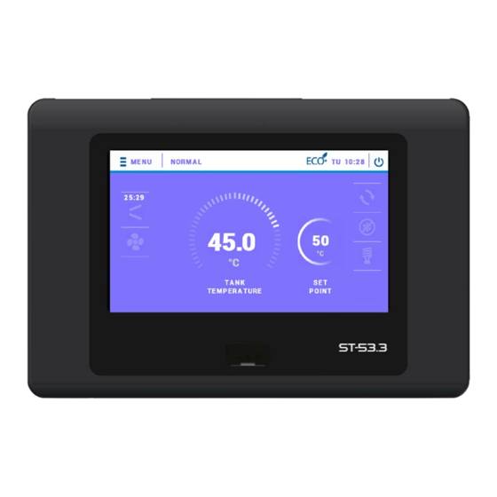
Energia zgromadzona w zasobach naturalnych ma zbyt niską temperaturę, aby mogła być bezpośrednio wykorzystana do ogrzewania. Sterownik EU-53.3 jest przystosowany do obsługi kolektora słonecznego. Parametry pracy dotyczące kolektora słonecznego dostępne są w menu serwisowym sterownika. Sterownik EU-53.3 może pracować według różnych schematów pracy pompy: •... - Page 9 17. Ikona informująca o aktywności wentylatora oraz temperaturze zewnętrznej 18. Ikona informująca o aktywności sprężarki oraz jej temperatura kontrolna Duży wyświetlacz dotykowy i czytelnie zaprojektowana grafika sterownika EU-53.3 pozwala na bardzo wygodną i niemal intuicyjną obsługę szeregu urządzeń, w jakie wyposażona jest pompa ciepła.
-
Page 10: Montaż Sterownika
IV. MONTAŻ STEROWNIKA Sterownik powinien być montowany przez osobę z odpowiednimi kwalifikacjami. OSTRZEŻENIE Niebezpieczeństwo dla życia w wyniku porażenia prądem elektrycznym na przyłączach pod napięciem. Przed pracami przy regulatorze należy odłączyć dopływ prądu i zabezpieczyć przed przypadkowym włączeniem. OSTRZEŻENIE Błędne podłączenie przewodów może spowodować uszkodzenie regulatora! W tylnej części sterownika znajdują... - Page 11 Przykładowy schemat instalacji i podpięcia: Przykładowy schemat instalacji i podpięcia w przypadku stosowania kolektora słonecznego:...
-
Page 12: Menu Sterownika
Sprężarka Czujnik kontrolny Wentylator Czujnik zbiornika Presostat niskiego ciśnienia Zawór rozmrażania Presostat wysokiego ciśnienia Grzałka Czujnik solara Pompa dodatkowa Czujnik parownika Pompa cyrkulacyjna Czujnik zewnętrzny Anoda Czujnik kotła V. MENU STEROWNIKA naciśnięciu ikony menu użytkownik przechodzi przeglądu kart poszczególnymi funkcjami. Aby przejść... -
Page 13: Temperatura Zadana Zbiornika
TEMPERATURA ZADANA ZBIORNIKA Funkcja ta służy do ustawienia temperatury zadanej zbiornika; temperaturę tą można również zmienić bezpośrednio z ekranu głównego sterownika po kliknięciu w zasobnik. ANTYZAMARZANIE Przy pomocy tej funkcji użytkownik precyzuje działania antyzamarzania, które służy ochronie instalacji przed zamarzaniem. Po spadku temperatury poniżej określonego progu temperatury (fabrycznie ustawiony próg to 5°C) grzałka załącza się... -
Page 14: Harmonogram Kolektora
STEROWANIE POKOJÓWKĄ Po załączeniu opcji <Włącz> funkcja pozwala na sterowanie regulatorem pokojowym. W tym celu należy wpiąć regulator pokojowy w odpowiednie miejsce w sterowniku EU-53.3 (patrz schemat montażu). MODUŁ ETHERNET Moduł internetowy to urządzenie pozwalające na zdalną kontrolę pracy instalacji. Użytkownik może kontrolować na ekranie komputera, tabletu, czy telefonu komórkowego stan wszystkich urządzeń... -
Page 15: Czas Pracy
CZAS PRACY Po wejściu w tę opcję pokazuje się ekran czasu pracy poszczególnych urządzeń: pompa ciepła, sprężarka, anoda, grzałka, pompa cyrkulacyjna. MENU SERWISOWE Aby uruchomić menu serwisowe sterownika należy wprowadzić czterocyfrowy kod dostępu. Fabrycznie kod ten ustawiony jest na: 1111. W razie potrzeby kod ten można zmienić na inny w menu serwisowym. CZUWANIE Funkcja ta pozwala załączyć... -
Page 16: Menu Serwisowe
MENU SERWISOWE Aby uruchomić menu serwisowe sterownika należy wprowadzić czterocyfrowy kod dostępu. W razie potrzeby kod ten można zmienić na inny w menu serwisowym. Obsługa menu serwisowego odbywa się analogicznie jak menu główne – po wejściu do menu serwisowego użytkownik przechodzi do przeglądu kart z poszczególnymi funkcjami. -
Page 17: Min.temperatura Pracy
• Temperatura końca rozmrażania - Parametr ten określa wartość temperatury parownika, po osiągnięciu której zostaje zakończony proces rozmrażania a sterownik powraca do normalnego trybu pracy. • Czas trwania blokady rozmrażania - Parametr określa czas pracy sprężarki, jaki musi upłynąć, aby możliwe było uruchomienie procesu rozmrażania. -
Page 18: Parametry Dodatkowego Źródła Ciepła
PARAMETRY DODATKOWEGO ŹRÓDŁA CIEPŁA PARAMETRY KOLEKTORA SŁONECZNEGO • Delta załączenia pompy- Funkcja ta określa różnicę pomiędzy temperaturą kolektora i zbiornika, przy której pompa zaczyna pracować (jest to wartość progowa załączenia pompy). • Delta wyłączenia pompy - Funkcja ta określa różnicę pomiędzy temperaturą kolektora i zbiornika, przy której pompa wyłączy się... -
Page 19: B) Parametry Kotła
W przypadku próbkowania czasowego pompa załącza się z częstotliwością określoną przez użytkownika w parametrze Przerwa próbkowania na czas określony w parametrze Czas próbkowania. Niezależnie od rodzaju próbkowania nie będzie ono aktywne jeśli temperatura kolektora spadnie poniżej wartości progu załączenia próbkowania. PARAMETRY KOTŁA •... - Page 20 PRESOSTAT WYSOKIEGO CIŚNIENIA Parametr pozwala na wybór stosowanego rodzaju presostatu wykrywającego wysokie ciśnienie – zwierny lub rozwierny. PRESOSTAT NISKIEGO CIŚNIENIA Parametr pozwala na wybór stosowanego rodzaju presostatu wykrywającego niskie ciśnienie – zwierny lub rozwierny. LEGIONELLA 17.1. TEMPERATURA FUNKCJI LEGIONELLA Jest to temperatura zadana podczas trwania dezynfekcji termicznej (funkcja Legionella). 17.2.
- Page 21 TEST USB Funkcja przeznaczona dla serwisantów. Pozwala na przetestowanie wejścia USB w sterowniku. MENU PRODUCENTA Opcja ta jest dostępna wyłącznie dla producenta sterownika.
- Page 22 VII. ZABEZPIECZENIA W celu zapewnienia maksymalnie bezpiecznej i bezawaryjnej pracy regulator posiada kilka zabezpieczeń. W przypadku wystąpienia alarmu załącza się sygnał dźwiękowy i na wyświetlaczu pojawia się odpowiedni komunikat. Aby sterownik powrócił do pracy należy wcisnąć OK na ekranie dotykowym. W alarmie możliwa jest praca ręczna, ale należy całkowicie się...
- Page 23 VIII. KONSERWACJA W sterowniku EU-53.3 należy przed sezonem grzewczym i w czasie jego trwania sprawdzić stan techniczny przewodów. Należy również sprawdzić mocowanie sterownika, oczyścić z kurzu i innych zanieczyszczeń. IX. AKTUALIZACJA OPROGRAMOWANIA Aby wgrać nowe oprogramowanie należy wyłączyć sterownik z sieci. Do gniazda USB należy włożyć PenDrive z nowym oprogramowaniem.
- Page 24 Firma TECH STEROWNIKI Sp. z o. o. Sp. k., z siedzibą w Wieprzu 34-122, przy ulicy Biała Droga 31, deklaruje na wyłączną odpowiedzialność, że produkowany przez nas sterownik EU-53.3, spełnia wymagania dyrektywy Parlamentu Europejskiego i Rady 2014/35/UE z dnia 26 lutego 2014 roku w sprawie harmonizacji ustawodawstw państw członkowskich odnoszących się...
- Page 27 EU-53.3...
- Page 28 TABLE OF CONTENTS SAFETY ..................................30 DESCRIPTION OF THE DEVICE ........................... 31 III. PRINCIPLE OF OPERATION ............................32 INSTALLATION ................................34 CONTROLLER MENU ..............................36 PARTY MODE................................36 HEATER .................................. 36 LEGIONELLA MODE ..............................36 TIME SETTINGS............................... 36 DATE SETTINGS ..............................36 TANK PRE-SET TEMPERATURE ..........................
- Page 29 ECO- ECO+ THRESHOLD HYSTERESIS ........................43 SYSTEM PROTECTION............................. 43 EMERGENCY TEMPERATURE..........................43 COMPRESSOR DELAY ............................. 43 MIN.COMPRESSOR PAUSE TIME ..........................43 HIGH PRESSURE SWITCH ............................43 LOW PRESSURE SWITCH ............................43 LEGIONELLA ................................43 17.1. LEGIONELLA TEMPERATURE .......................... 43 17.2. LEGIONELLA DURATION ..........................
-
Page 30: Safety
SAFETY Before using the device for the first time the user should read the following regulations carefully. Not obeying the rules included in this manual may lead to personal injuries and device damage. The user's manual should be stored carefully. In order to avoid accidents and errors it should be ensured that every person using the device has familiarized themselves with the principle of operation as well as security functions of the device. -
Page 31: Description Of The Device
II. DESCRIPTION OF THE DEVICE EU-53.3 controller is intended for controlling an air-to-water heat pump. The main task of the device is to control the operation of the compressor, fan, heater, circulating pump and the additional heat source pump. Functions performed by the controller: •... -
Page 32: Principle Of Operation
The EU-53.3 controller is adapted for the operation of a solar collector. The operation parameters regarding the solar collector are available in the controller's service menu. - Page 33 Icon indicating fan activity and outdoor temperature Icon informing about compressor activity and its control temperature A large touch screen and clearly designed graphics of EU-53.3 controller enable the user fast and intuitive control of a range of devices comprising the heat pump equipment.
-
Page 34: Installation
IV. INSTALLATION The controller should be installed by a qualified person. WARNING Risk of fatal electric shock from touching live connections. Before working on the regulator, switch off the power supply and prevent it from being switched on again. WARNING Incorrect connection of cables may lead to regulator damage! The rear part of the controller contains couplings to which the sensors as well as devices operated by the controller should be connected. - Page 35 An exemplary diagram of installation and connections: An exemplary diagram of installation and connections when a solar collector is used:...
-
Page 36: Controller Menu
Compressor Control sensor Tank sensor Low pressure switch Defrost valve High pressure switch Heater Solar sensor Additional pump Evaporator sensor Circulating pump External sensor Anode CH boiler sensor V. CONTROLLER MENU Tap on the menu icon to view the parameters tabs. The controller offers five tabs, each of them includes up to three functions. In order to edit a particular parameter, tap on its icon. -
Page 37: Tank Pre-Set Temperature
TANK PRE-SET TEMPERATURE This function is used to set the pre-set tank temperature; this temperature may also be changed directly from the controller's Main Screen after clicking on the reservoir. ANTI-FREEZE This option is used to adjust the settings of anti-freeze function which protects the system against freezing. If the temperature drops below the pre-defined value (default setting: 5˚C), the regulator activates the heater or the heat pump. -
Page 38: Collector Schedule
COLLECTOR SCHEDULE This option is used to define daily solar collector operation program for particular days of the week, with the accuracy of an hour. Select the hours when the heat pump will be active (the heat pump remains inactive). Once the daily settings have been configured, tap on the icon on the right-hand side of the screen to confirm. -
Page 39: Amount Of Energy Produced
AMOUNT OF ENERGY PRODUCED This parameter enables the user to check how much energy was produced in different time periods: daily, weekly, monthly, annually. It also shows how much energy was used. AMOUNT OF ENERGY PRODUCED - MONTH This parameter enables the user to check how much energy was produced by the heat pump in different months. OPERATION TIME This parameter enables the user to check the operation time of particular devices: heat pump, compressor, anode, heater and circulating pump. -
Page 40: Service Menu
SERVICE MENU In order to access the service menu, it is necessary to enter a 4-digit access code. Default code is 1111. If needed, the code may be changed in the service menu. The servicing menu is operated like the main menu - after entering the servicing menu, the user proceeds to the review of cards with particular functions. -
Page 41: Minimum Working Temperature
If the external temperature drops below the threshold value, the controller checks how long the compressor has been active. When the defrost lock time elapses, the controller moves on to the next phase of defrost process. • Forced defrost time - This parameter is used to define the length of time after which the defrosting process will be started regardless of delta value. -
Page 42: Parameters Of Additional Source
• Collector overheat temperature - This is alarm temperature of the solar collector at which the pump is forced to activate in order to cool down the solar panels. The discharge of warm water will take place regardless of the tank pre-set temperature. -
Page 43: Pre-Set Tank Temperature Hysteresis
• Operation of Heat Source by Weekly Control This function defines whether the additional heat source pump will switch on simultaneously with the set weekly program (Switch On) or whether it will operate independently according to the set activation temperature (Switch Off). PRE-SET TANK TEMPERATURE HYSTERESIS This option is used to set the hysteresis of the tank temperature. - Page 44 17.3. MAXIMUM TIME OF LEGIONELLA It is the maximum time of the disinfection process (Legionella) from the moment of its activation (regardless of the current temperature at that time). If the tank fails to reach the pre-set disinfection temperature or maintain the temperature for the time period defined as Legionella duration, the controller returns to standard operation after the maximum time.
- Page 45 VII. PROTECTIONS In order to ensure the maximum safe and reliable operation, the regulator has several protections. In the case of alarm, a sound signal is activated and a relevant message is shown on the display.In order for the controller to return to operation, the user should press OK on the touchscreen.
- Page 46 VIII. MAINTENANCE Before and during the heating season the EU-53.3 controller should be checked for the condition of its cables. You should also check if the controller is properly mounted and clean it if dusty or dirty. IX. SOFTWARE UPDATE In order to install new software, disconnect the controller from the power supply.
- Page 47 EU Declaration of conformity Hereby, we declare under our sole responsibility that EU-53.3 manufactured by TECH, headquartered in Wieprz Biała Droga 31, 34-122 Wieprz, is compliant with: • Directive 2014/35/EU of the European Parliament and of the Council of February 26, 2014 on the...
Need help?
Do you have a question about the EU-53.3 and is the answer not in the manual?
Questions and answers