
Subscribe to Our Youtube Channel
Related Manuals for Rice Lake Load Ranger Series


Summary of Contents for Rice Lake Load Ranger Series
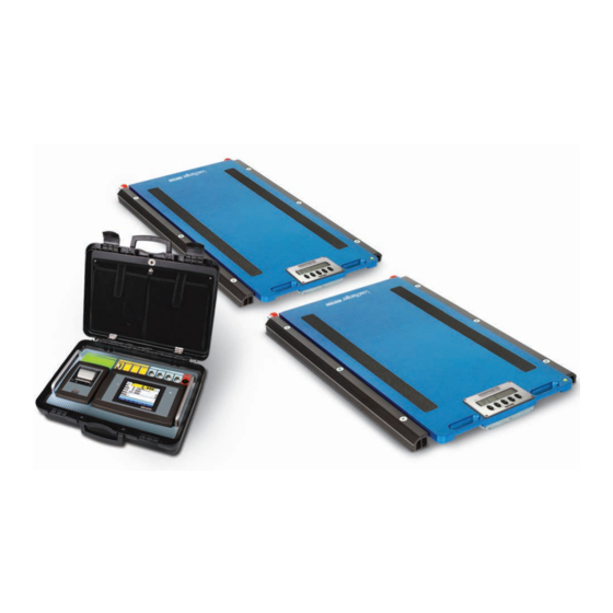
- Page 1 Load Ranger Wheel Weigh Pad System Technical Manual September 11, 2019 PN 189612 Rev B...
- Page 2 All information contained within this publication is, to the best of our knowledge, complete and accurate at the time of publication. Rice Lake Weighing Systems reserves the right to make changes to the technology, features, specifications and design of the equipment without notice.
-
Page 3: Table Of Contents
Change Setpoint Functions ..............28 Technical training seminars are available through Rice Lake Weighing Systems. - Page 4 Compliance ..................52 Rice Lake continually offers web-based video training on a growing selection of product-related topics at no cost.
-
Page 5: Introduction
Do not operate or work on this equipment unless this manual has been read and all instructions are understood. Failure to follow the instructions or heed the warnings could result in injury or death. Contact any Rice Lake Weighing Systems dealer for replacement manuals. -
Page 6: Available Models
Load Ranger Wheel Weigh Pad System Available Models RF-XWD RF-WD RF-MD Loading Surface Loading Surface Loading Surface 1' 10'' x 1' 4'' 2' 6'' x 1' 6'' 3' 1'' x 1' 8'' (564 x 400 mm) (750 x 450 mm) (950 x 500 mm) Features Loading Surface... -
Page 7: Accessories
Part No. Description 181881 Aluminum Ramp for Load Ranger MD Models 181882 Aluminum Ramp for Load Ranger WD Models 181883 Aluminum Ramp for Load Ranger XWD Models Table 1-1. Available Accessories © Rice Lake Weighing Systems ● All Rights Reserved... -
Page 8: Setup
Follow the procedures in the section to setup a Load Ranger system. Choosing the Weighing Area Load Ranger wheel weigh pads can be installed on most types of surfaces. For the best results, Rice Lake Weighing Systems recommends: • An area that is large enough to allow vehicles to easily maneuver under safe conditions •... -
Page 9: Positioning The Platforms
The display must be facing outwards in order to correctly transmit the wireless weighing data. Before positioning the platforms, ensure that the vehicle’s engine is off, with the first gear engaged and the CAUTION WARNING parking brake activated. © Rice Lake Weighing Systems ● All Rights Reserved... -
Page 10: Correct Platform Use
Load Ranger Wheel Weigh Pad System Only position platforms when the vehicle is stopped. Never stand in front or behind the vehicle when CAUTION WARNING positioning the platforms. Correct Platform Use Refer to the transit area and the positioning bands for the proper transit path and weighing location. Avoid transit over the display to preserve correct operation and to prevent accidental scratches. -
Page 11: Applications
The size and capacity of the third platform can differ from those of the other platforms Four Platforms Applications include weighing two-axle vehicles, trailers, containers or other items with four support points. © Rice Lake Weighing Systems ● All Rights Reserved... - Page 12 Load Ranger Wheel Weigh Pad System Five Platforms Applications include weighing two-axle trailers with a support pin. When weighing both directions, a sixth platform can be used. The size and capacity of the fifth platform can differ from those of the other platforms Optional sixth platform Six Platforms Applications include weighing three-axle vehicles or structures with six support points.
-
Page 13: 2.4.2 Hybrid Wireless Setup
Eight to Fourteen Platforms Applications include weighing multi-axle vehicles or structures with several support points in a single step. © Rice Lake Weighing Systems ● All Rights Reserved... -
Page 14: 2.4.3 Wired Setup
Load Ranger Wheel Weigh Pad System 2.4.3 Wired Setup A wired system allows for weighing with two to four connected wheel weigh pads. Figure 2-2. Recommend Cable Placement The data communication port is located on the underside of the wheel weigh pad. For the RF-MD the port is located at the handle end of the platform and is the port further from the edge. -
Page 15: Weighing Of Objects Or Structures
Do not set the load on the weigh pad display. Always position the displays of the platforms towards the outside IMPORTANT of the structure being weighed in order to correctly transmit the weight reading data. © Rice Lake Weighing Systems ● All Rights Reserved... -
Page 16: Operation
Load Ranger Wheel Weigh Pad System Operation The Load Ranger wheel weigh pads can be operated independently or with an Ai-1 indicator. The following section provides an overview and procedures for both types of applications. Weigh Pad Display DATA DIAG MODE Figure 3-1. -
Page 17: Display Features
11. Press to confirm. briefly displays and all the changed parameters are saved. 12. Repeat steps for all wheel weigh pads in the system. Figure 3-3. Wheel Weigh Pad Positioning © Rice Lake Weighing Systems ● All Rights Reserved... -
Page 18: Ai-1 Indicator Display
Load Ranger Wheel Weigh Pad System Ai-1 Indicator Display GROSS GROSS 08:32 08:32 Max 19800lb d=10lb Min 200lb (1 ~ 6) Max 6600lb d=1lb Min 20lb (1 ~ 2) VEHICLE AXLES (lb) AXLES (lb): N. 0 TARE TOTAL TARE VEHICLE GRAVITY CENTRE x=------ m y=------ m... -
Page 19: Pairing Ai-1 Indicator With Weigh Pads
1 scale/s 4. Press Number of scales Number of scales Cancel Figure 3-6. Select Number of Weigh Pads 5. Select the number of wheel weigh pads to be used. 6. Press PAIR © Rice Lake Weighing Systems ● All Rights Reserved... - Page 20 Load Ranger Wheel Weigh Pad System 7. Press WWS configuration 8. Press WWS pairing 9. Press to start pairing process. A prompt displays (Figure 3-7). Do not press anything at this time. 10. Turn off all wheel weigh pads. 11. Turn on the first weigh pad only (pad assigned ID 01). WWS pairing Start pairing? Please turn on WWS one by one.
- Page 21 • The Password window displays — Press , depending if a password is needed or not • The Technical Setup window displays — Press to convert the indicator units to match the weigh pad units © Rice Lake Weighing Systems ● All Rights Reserved...
-
Page 22: Standard Ai-1 Indicator Functions
Load Ranger Wheel Weigh Pad System Standard Ai-1 Indicator Functions 3.3.1 Zeroing Weigh Pads with Indicator The Ai-1 indicator can zero all of the connected weigh pads at once or individually. The annunciator displays if the scale weight is zeroed. To zero the whole system (all of the connected weigh pads), make sure is displayed and press To zero an individual weigh pad, the corresponding scale number (example:... -
Page 23: Weighing Procedure
7. Press to execute the printout of the total weight, minus the tare value if needed. TOTAL 8. Remove the vehicle from the platforms. © Rice Lake Weighing Systems ● All Rights Reserved... -
Page 24: Axle-Weighing System
Load Ranger Wheel Weigh Pad System 3.4.2 Axle-Weighing System An axle-weighing system consists of only two platforms. With this method, each axle of the vehicle is weighed separately and then added together. The Ai-1 indicator displays the weight of the current axle and the corresponding individual wheels, while also listing the previous axle weights and the total gross or net weight. -
Page 25: Battery Recharging
3. Press the cell of the text to be changed. Example: Press 0002 TOWN 4. Use the displayed keyboard to enter the desired text. 5. Press to confirm text. 6. Press to return to the secondary weigh screen. © Rice Lake Weighing Systems ● All Rights Reserved... -
Page 26: Vehicle Database
Load Ranger Wheel Weigh Pad System Vehicle Database The Description 1 text displays to the right of the vehicle database number. When vehicle entry is used, Description 1 and Description 2 is added to the printed ticket (Section 3.8 on page 25). -
Page 27: Delete Vehicle
Note 2. Press . A confirmation prompt displays. DESELECT 3. Press to confirm or press to cancel. If confirmed, display returns to primary weigh screen and the vehicle cell is empty. © Rice Lake Weighing Systems ● All Rights Reserved... -
Page 28: Temporary Vehicle
Load Ranger Wheel Weigh Pad System 3.7.6 Temporary Vehicle 1. Press the vehicle cell on the primary weigh screen to view the current list of vehicle database entries. 2. Press . The previous temporary entry will be cleared. 0000 Temporary Vehicle 0001/0499 Vehicle 0001/0499 Description 1... -
Page 29: Print Formats
Figure 3-18. Change Print Format Table 5. Press within the FORMAT column to change the print format associated with the corresponding print function. 6. Press twice to save changes and return to the secondary weigh screen. © Rice Lake Weighing Systems ● All Rights Reserved... -
Page 30: Default Print Formats
Load Ranger Wheel Weigh Pad System 3.8.1 Default Print Formats Printout Heading Rice Lake Section 4.2.4 on page 32 Weighing Systems 800-472-6703 Vehicle Description 1 and 2 RLWS TRUCK 1 Section 3.7 on page 22 WI RL4321 Date and Time... - Page 31 550 = 1000 WHEEL 2300lb WHEEL 2250lb AXLE 4550lb Figure 3-30. Print Format 12 Figure 3-25. Print Format 7 VEHICLE RLWS TRUCK 2 WI RL8642 25/06/18 09:43 Figure 3-26. Print Format 8 © Rice Lake Weighing Systems ● All Rights Reserved...
-
Page 32: Setpoints
Load Ranger Wheel Weigh Pad System Setpoints Follow the procedure in this section to set the setpoint thresholds. See Section 3.9.1 to change the setpoint functions. 1. Press to switch the indicator display to the secondary weigh screen. >> 2. Press to view the output setpoint settings. -
Page 33: Configuration
Settings: , , , , , , , – Weighing filter – must be set to for correct operation; Contact Rice Lake Weighing systems to use additional filters – Adjust display screen Backlighting; Settings: , (always on), (on when weight is unstable) ... -
Page 34: Keyboard Lock
Load Ranger Wheel Weigh Pad System Parameter Description – Advanced Calibration parameters: – decimal point; Settings: , , , – division size; Settings: , , ,, ,, – unit of measure; Settings: , , , ... -
Page 35: Metrological Version
4. Set the date and time. Date is set DD / MM / YY. Time is set in military standard time. Date and time can also be set in weighing mode by pressing within the time cell in the upper left corner of the screen. Note © Rice Lake Weighing Systems ● All Rights Reserved... -
Page 36: Date And Time Password
Load Ranger Wheel Weigh Pad System 4.2.3 Date and Time Password 1. Press First Programming 2. Press 3. Press Date and time password 4.2.4 Printout Headings 1. Navigate to the Technical Setup menu. See Section 4.2 on page 2. Press 3. -
Page 37: Center Of Gravity
Coordinates unit of measure Scale 1 5. Use displayed keyboard to enter units abbreviation and press 6. Press , then press to save changes. Indicator restarts and returns to the weigh screen. © Rice Lake Weighing Systems ● All Rights Reserved... -
Page 38: Calibration
Load Ranger Wheel Weigh Pad System Calibration This section provides the procedures necessary to calibrate the Load Ranger wheel weigh pads through the built-in displays and with the Ai-1 indicator. When using the Ai-1 indicator with the weigh pads, skip to Section 5.2 on page 35 to calibrate all of the weigh pads through the Ai-1 indicator. -
Page 39: Zero Calibration Procedure
. Calibration acquisition of point 1 message displays. 7. Press . Calibration point 1 weight prompt displays. 8. Enter the weight value of the calibration point and press . Calibration load weight prompt displays. © Rice Lake Weighing Systems ● All Rights Reserved... -
Page 40: Zero Calibration
Load Ranger Wheel Weigh Pad System 9. Load the scale with a test weight equal to the entered value and press . Once procedure is complete, a successful calibration message displays. 10. Press 11. Press to return to the calibration menu. 12. -
Page 41: Maintenance
• Remove any debris from the weighing area, as well as the area under the wheel weigh pads, that may prevent the loading surface from bending correctly • Clean the platform with non-aggressive substances • Periodically check the condition of the connection cables • Fully charge the battery before prolonged non-use © Rice Lake Weighing Systems ● All Rights Reserved... -
Page 42: Accessory Assembly
Load Ranger Wheel Weigh Pad System Accessory Assembly 6.3.1 Display Cover 6.3.2 Transport Wheels www.RiceLake.com Visit our website... -
Page 43: Aluminum Ramps
The wheels may need to be loosened to insert the threaded pins. Use a rubber mallet if needed, but make sure the threads are facing outwards. The pin is slightly wider on the threaded side. Note © Rice Lake Weighing Systems ● All Rights Reserved... -
Page 44: Board Diagram
Load Ranger Wheel Weigh Pad System Board Diagram POWER IN: 4,8...12Vdc Auto switch on RS232 COM 2 RS232 COM 1 SIG+ SIG- SEN+ CELL3 CELL4 Legal SEN- Internal use EXC+ CELL2 RS232/RS485 EXC- COM 1 SENSE CELL1 SENSOR BOOT +5V GND 01 02 I/O BOARD - CLOCK - ALIBI MEMORY SEN+... -
Page 45: Wiring Schemes
SIG+ White RS232 COM 2 RS232 COM 1 SIG- RS232/RS485 COM 1 CELL3 CELL4 SEN+ BOOT D 01 02 SEN- EXC+ Black CELL2 EXC- SENSE CELL1 SENSOR +5V GND 01 02 © Rice Lake Weighing Systems ● All Rights Reserved... -
Page 46: Power Supply Wiring
Load Ranger Wheel Weigh Pad System 6.5.2 Power Supply Wiring Charging Connector Position Pin Configuration Brown (+) White (-) Board Connection Location On Board POWER IN: 4,8...12Vdc Brown SIG+ SIG- SEN+ CELL3 CELL4 SEN- EXC+ CELL2 RS232/RS485 EXC- COM 1 CELL1 SENSE SENSOR... -
Page 47: Rs485 Wiring
Board Connection Location On Board RS232 COM 2 RS232 COM 1 SIG+ SIG- SEN+ CELL3 CELL4 SEN- EXC+ CELL2 EXC- CELL1 SENSE SENSOR BOOT +5V GND 01 02 RS232/RS485 COM 1 © Rice Lake Weighing Systems ● All Rights Reserved... -
Page 48: Bluetooth Connection
The Bluetooth module is built into the platform. The antenna is in an optimal position for continuous communication. The antenna is protected against impact and crushing. Do not modify the angle or the position of the antenna. IMPORTANT Only use the provided antenna or a Rice Lake Weighing Systems replacement. Bluetooth Antenna Position Board Connection... -
Page 49: Calibration Jumper
4 wires, check that the sense jumpers are inserted Bluetooth module error The Bluetooth module is not responding (Section 6.8 on page © Rice Lake Weighing Systems ● All Rights Reserved... -
Page 50: Frequently Asked Questions
Load Ranger Wheel Weigh Pad System Frequently Asked Questions Communication Problems in a Wireless System • Ensure there are no other devices communicating on the same frequencies • Make sure there are no obstructions between the indicator and the platforms •... -
Page 51: Specifications
This device may not cause harmful interference. This device must accept any interference received, including interference that may cause undesired operation. Radio certificate number: Bluetooth: US: PVH0946; Canada: 5325A-0946 WiFi: US: ZXVHLK-RM04 Warranty: Two-year limited warranty © Rice Lake Weighing Systems ● All Rights Reserved... -
Page 52: Dimensions
Load Ranger Wheel Weigh Pad System Dimensions RF-MD RF-WD RF-XWD 1' 8'' 1' 10'' 2' 8'' 3' 3'' 2.28'' 2.28'' 2.28'' 1' 4'' 1' 6'' 1' 8'' 1' 10'' 2' 6'' 3' 1'' A, B and C represent the overall platform dimensions D and E represent the loading surface dimensions Table 7-1. -
Page 53: Replacement Load Cells
Max=1000kg. Nickeled steel, IP68 protection degree, 1000 Ohm output resistance. Shear beam approved load cell, C3, 183799 2500 kg Max=2500kg. Nickeled steel, IP68 protection degree, 1000 Ohm output resistance. Table 7-2. Load Cells © Rice Lake Weighing Systems ● All Rights Reserved... -
Page 54: Replacement Parts
Load Ranger Wheel Weigh Pad System Replacement Parts Description 192596 Junction box 192607 Protective display glass 192608 Extension keys (kit x 5) for RF-XWD 192624 Extension keys (kit x 5) for RF-MD/RF-WD 192609 CPU board 188482 NIMH battery pack 192616 Adhesive film 183798 SBX2000 2,000 kg load cell... - Page 55 Bluetooth board connector cable 192587 Front panel 192591 Power adaptor 120-230VAC 192581 Galvanized case 192589 Display board 192590 Front panel 192585 CPU board 192586 Frame, jumper protection Table 7-4. Load Ranger Ai-1 Replacement Parts © Rice Lake Weighing Systems ● All Rights Reserved...
-
Page 56: Compliance
Load Ranger Wheel Weigh Pad System Compliance DECLARATIONOF CONFORMITY Load Ranger 2014/30/EU EMC EN 61000-6-2:2015, EN 61000-6-4:2007+A1:2011, EN61326-1:2013, EN55011:2009 +A1:2010 2014/35/EU LVD EN 61010-1:2010 2011/65/EU RoHS EN 50581:2012 Devices marked with the legal metrology marking: / Geräte, die mit der gesetzlichen Messtechnik gekennzeichnet sind: / Appareils marqués du marquage métrologique légale: 2014/31/EU NAWI... - Page 58 Specifications subject to change without notice. Rice Lake Weighing Systems is an ISO 9001 registered company. 230 W. Coleman St. • Rice Lake, WI 54868 • USA U.S. 800-472-6703 • Canada/Mexico 800-321-6703 • International 715-234-9171 • Europe +31 (0)26 472 1319...
Need help?
Do you have a question about the Load Ranger Series and is the answer not in the manual?
Questions and answers