Quectel 5G Module Series User Manual
Hide thumbs
Also See for 5G Module Series:
- Hardware design (87 pages) ,
- User manual (47 pages) ,
- User manual (30 pages)

Related Manuals for Quectel 5G Module Series


Summary of Contents for Quectel 5G Module Series
- Page 1 RMU500-EK User Guide 5G Module Series Rev. RMU500-EK_User_Guide_V1.0 Date: 2020-02-18 Status: Preliminary www.quectel.com...
- Page 2 QUECTEL OFFERS THE INFORMATION AS A SERVICE TO ITS CUSTOMERS. THE INFORMATION PROVIDED IS BASED UPON CUSTOMERS’ REQUIREMENTS. QUECTEL MAKES EVERY EFFORT TO ENSURE THE QUALITY OF THE INFORMATION IT MAKES AVAILABLE. QUECTEL DOES NOT MAKE ANY WARRANTY AS TO THE INFORMATION CONTAINED HEREIN, AND DOES NOT ACCEPT ANY LIABILITY FOR ANY INJURY, LOSS OR DAMAGE OF ANY KIND INCURRED BY USE OF OR RELIANCE UPON THE INFORMATION.
-
Page 3: About The Document
5G Module Series RMU500-EK User Guide About the Document Revision History Version Date Author Description Tom TANG/ V1.0 2020-02-18 Initial Shaky LIN RMU500-EK_User_Guide 2 / 26... -
Page 4: Table Of Contents
5G Module Series RMU500-EK User Guide Contents About the Document ........................... 2 Contents ............................... 3 Table Index ..............................4 Figure Index ..............................5 Introduction ............................6 1.1. Safety Information ........................7 General Overview ..........................8 2.1. Key Features ........................... 8 2.2. - Page 5 5G Module Series RMU500-EK User Guide Table Index Table 1: Key Features ..........................8 Table 2: Component Functions of the EVB ....................9 Table 3: Accessories List ........................... 10 Table 4: Pin Definition of J401 ........................15 Table 5: Description of Status Indication LEDs ..................16 Table 6: Related Documents ........................
- Page 6 5G Module Series RMU500-EK User Guide Figure Index Figure 1: Component Placement of EVB (Top Side) ................... 9 Figure 2: EVB Top View ..........................10 Figure 3: EVB Power Supply Interfaces ..................... 12 Figure 4: Connection Between RM500Q Module and EVB ............... 13 Figure 5: USB Connector ...........................
-
Page 7: Introduction
5G Module Series RMU500-EK User Guide Introduction This document describes how to use the evaluation board of Quectel RM500Q module. It is an assistant tool for engineers to develop and test the module. RMU500-EK_User_Guide 6 / 26... -
Page 8: Safety Information
RM500Q module. Manufacturers of the cellular terminal should send the following safety information to users and operating personnel, and incorporate these guidelines into all manuals supplied with the product. If not so, Quectel assumes no liability for customers’ failure to comply with these precautions. -
Page 9: General Overview
5G Module Series RMU500-EK User Guide General Overview Quectel supplies RMU500-EK for designers to develop applications based on Quectel RM500Q module. This EVB can test basic functionalities of the module. 2.1. Key Features The following table describes the detailed features of RMU500-EK. -
Page 10: Component Placement Of Evb
5G Module Series RMU500-EK User Guide 2.2. Component Placement of EVB J301 Shielding Cover J101 Shielding Cover D104 D107 Type-B J401 Figure 1: Component Placement of EVB (Top Side) Table 2: Component Functions of the EVB Functions Component No. Description... -
Page 11: Top View Of Evb
5G Module Series RMU500-EK User Guide 2.3. Top View of EVB Top view of the EVB is shown as below. Figure 2: EVB Top View 2.4. EVB Kit Accessories All accessories of the EVB are listed as below. Table 3: Accessories List... - Page 12 5G Module Series RMU500-EK User Guide Heatsink Heatsink AL6063 black anodized Including module’s related documents, tools, USB Flash Drive drivers, etc. Used to clamp RM500Q, antennas and Screws heatsink to EVB RMU500-EK_User_Guide 11 / 26...
-
Page 13: Evb Components Application
5G Module Series RMU500-EK User Guide EVB Components Application This chapter mainly describes the following EVB components application: Power supply USB interface M.2 interface (U)SIM interface RF cables & antennas It also provides information about status indication LEDs to help customers use the EVB. -
Page 14: Interface
5G Module Series RMU500-EK User Guide 3.2. M.2 Interface The M.2 connector is designed to accommodate the module. The following figure shows the connection between RM500Q module and EVB. Figure 4: Connection Between RM500Q Module and EVB 3.3. USB Interface The EVB provides a Type-C USB connector J301 for connection with a host. -
Page 15: U)Sim Card Connector
5G Module Series RMU500-EK User Guide Figure 6: Connection Between PC and EVB One end of Type-A is connected to the computer and the other end is connected to the auxiliary power supply. 3.4. (U)SIM Card Connector The EVB has an 8-pin push-push type (U)SIM card (2.95V or 1.8V) connector J401. The following figure shows the simplified connector schematic for J401. - Page 16 5G Module Series RMU500-EK User Guide The figure and table below illustrate the pin assignment and pin definition of (U)SIM card connector J401. Figure 8: Pin Assignment of (U)SIM Card Connector J401 Table 4: Pin Definition of J401 Pin No.
-
Page 17: Status Indicator
5G Module Series RMU500-EK User Guide 3.5. Status Indicator The EVB provides two status indication LEDs. The following figure shows the positions of these LED indicators. Figure 9: Status Indicators Table 5: Description of Status Indication LEDs Reference No. Description Indicates whether the power supply for the module is ready. - Page 18 5G Module Series RMU500-EK User Guide Antenna Π m Module atching circuit 0Ω Figure 10: Reference Design for Antenna The matching circuit is composed of C1, C2 and R1 for antenna impedance modification. By default, value of R1 is 0Ω, while C1 and C2 are not mounted.
-
Page 19: Assembling Steps
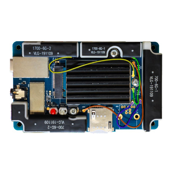
5G Module Series RMU500-EK User Guide Table 6: Recommended Antenna Specifications Antenna Specification Size: TBD 700-6G-1 Frequency Range: 0.7~6GHz Input Impedance: 50Ω Size: TBD 700-6G-2 Frequency Range: 0.7~6GHz Input Impedance: 50Ω Size: TBD 1700-6G-1 Frequency Range: 1.7~6GHz Input Impedance: 50Ω... - Page 20 5G Module Series RMU500-EK User Guide Stick the thermal pad, insert the module and lock the screw. Figure 14: Assembling Step 2 Connect the EVB and module with RF cables in accordance with the figure below. Figure 15: Assembling Step 3...
- Page 21 5G Module Series RMU500-EK User Guide Place the heatsink on the module and lock the screws. Figure 16: Assembling Step 4 Install the antennas in turn and lock the screws. Figure 17: Assembling Step 5 RMU500-EK_User_Guide 20 / 26...
- Page 22 5G Module Series RMU500-EK User Guide Finish the assembling. Figure 18: Assembling Step 6 RMU500-EK_User_Guide 21 / 26...
-
Page 23: Operation Procedures Illustration
PC to install the USB driver. For details about USB driver installation, please refer to document [1]. Figure 19: USB Ports Install and then use the QCOM tool provided by Quectel to realize communication between the module and the PC. The following figure shows the COM Port Setting field on QCOM: select correct “COM Port”... -
Page 24: Firmware Upgrade
5G Module Series RMU500-EK User Guide Figure 20: COM Port Setting Field on QCOM (USB AT Port Connection) 4.3. Firmware Upgrade The firmware of the module is upgraded via USB port by default, please follow the procedures below to upgrade firmware. -
Page 25: Power Off The Module
5G Module Series RMU500-EK User Guide 4.4. Power off the Module There are two ways to power off the module. Hardware shutdown: Disconnect USB cable and the module will be powered off. Software shutdown: Turn off the module using AT+QPOWD command. -
Page 26: Appendix A References
5G Module Series RMU500-EK User Guide Appendix A References Table 6: Related Documents Document Name Remark Quectel_LTE&5G_Windows_USB_Driver_ Installation guide of USB driver for LTE&5G Installation_Guide modules on Windows system Quectel_RM500Q_AT_Commands_Manual AT commands manual for RM500Q module Quectel_RM500Q_Hardware_Design Hardware design for RM500Q module... - Page 27 5G Module Series RMU500-EK User Guide Light Emitting Diode Microphone Not Connected Personal Computer Printed Circuit Board Pulse Code Modulation Power Output Radio Frequency Secure Digital Subscriber Identity Module UART Universal Asynchronous Receiver & Transmitter Universal Serial Bus (U)SIM (Universal) Subscriber Identity Module...
Need help?
Do you have a question about the 5G Module Series and is the answer not in the manual?
Questions and answers