
Related Manuals for Quectel 5GDM03-EV


Summary of Contents for Quectel 5GDM03-EV
- Page 1 5GDM03-EV EVB User Guide 5G Module Series Version: 1.0.0 Date: 2023-06-21 Status: Preliminary...
-
Page 2: Legal Notices
5G Module Series At Quectel, our aim is to provide timely and comprehensive services to our customers. If you require any assistance, please contact our headquarters: Quectel Wireless Solutions Co., Ltd. Building 5, Shanghai Business Park Phase III (Area B), No.1016 Tianlin Road, Minhang District, Shanghai... -
Page 3: Privacy Policy
Except as otherwise set forth herein, nothing in this document shall be construed as conferring any rights to use any trademark, trade name or name, abbreviation, or counterfeit product thereof owned by Quectel or any third party in advertising, publicity, or other aspects. -
Page 4: Safety Information
Manufacturers of the terminal should notify users and operating personnel of the following safety information by incorporating these guidelines into all manuals of the product. Otherwise, Quectel assumes no liability for customers’ failure to comply with these precautions. -
Page 5: About The Document
5G Module Series About the Document Revision History Version Date Author Description 2023-06-21 Kimi CHEN Creation of the document 1.0.0 2023-06-21 Kimi CHEN Preliminary 5GDM03-EV_EVB_User_Guide 4 / 37... -
Page 6: Table Of Contents
5G Module Series Contents Safety Information ............................ 3 About the Document ..........................4 Contents ..............................5 Table Index ............................... 6 Figure Index .............................. 7 Introduction ............................8 1.1. Applicable Modules ........................8 1.2. Special Mark ..........................8 Product Overview ..........................9 2.1. - Page 7 5G Module Series Table Index Table 1: Special Mark ..........................8 Table 2: Components & Functions ......................12 Table 3: Accessories List ........................14 Table 4: Description of Power Supply ..................... 15 Table 5: Description of USB Interface ..................... 17 Table 6: Description of (U)SIM Card Interfaces ..................
- Page 8 5G Module Series Figure Index Figure 1: Top View ............................ 9 Figure 2: Bottom View ..........................10 Figure 3: Top View for Component Placement ..................11 Figure 4: Bottom View for Component Placement ................... 12 Figure 5: Block Diagram of EVB Power Supply ..................15 Figure 6: EVB Power Supply Interface ....................
-
Page 9: Introduction
5G Module Series Introduction This user guide describes the application details of 5GDM03-EV EVB (evaluation board), which is an assistant tool for developers to develop applications and test basic functionalities of applicable modules. 1.1. Applicable Modules For details about the applicable modules of this EVB, see document [1]. -
Page 10: Product Overview
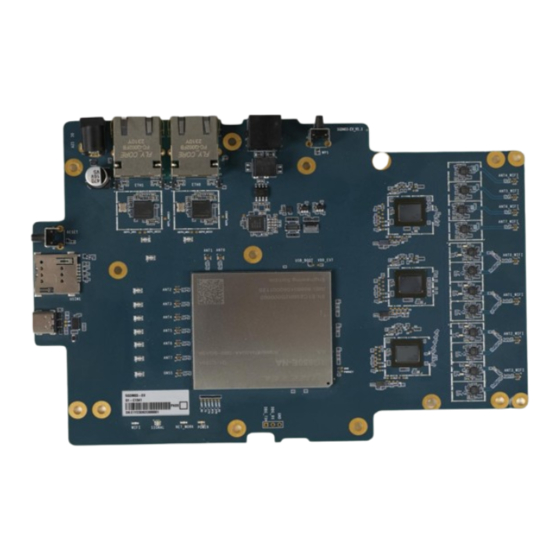
5G Module Series Product Overview 2.1. Top and Bottom Views The size of 5GDM03-EV EVB is 187 mm × 130 mm, and the top and bottom views are shown as below: Figure 1: Top View 5GDM03-EV_EVB_User_Guide 9 / 37... - Page 11 5G Module Series Figure 2: Bottom View 5GDM03-EV_EVB_User_Guide 10 / 37...
-
Page 12: Component Placement
5G Module Series 2.2. Component Placement 187 mm S4302 J3801 J3601 J4001 J0101 ANT4_WIFI RJ11 DC_12V J2201 RJ45 RJ45 ANT5_WIFI J2202 QEP8121 QEP8121 QFW7124 U0602 ANT6_WIFI SI32185 J2203 U3701 U3501 ANT7_WIFI QEP1_MDC QEP2_MDC U4001 J2204 QEP1_MDIO QEP2_MDIO J4702 J4701 ANT0_WIFI ANT1 ANT0 J2101... - Page 13 5G Module Series 187mm eSIM (option) U4201 Figure 4: Bottom View for Component Placement Table 2: Components & Functions Component RefDes. Description Comment ⚫ DC power supply: 12–14 V ⚫ Power Supply J0101 Power jack on the EVB Typical supply power: +12V/ 3 A ⚫...
- Page 14 5G Module Series Power supply ON/OFF D4311 indicator D4302 Network indicator Status Indicators* 4 LEDs available for signal indication D4308 Wi-Fi status indicator D0729 TBD* ⚫ Supports PHY QEP8121 (10/100/1000/2500 Mbps) U3701, ⚫ PHY Interface Supports PHY U3501 QEP8121/QEP8111 (10/100/1000 Mbps) ⚫...
-
Page 15: Kit Accessories & Assembly
3.1. Accessories Assembly This chapter will be offered in the next version. 3.2. Accessories List All accessories of the 5GDM03-EV EVB kit are listed as below. Please contact the supplier if there is something missing. Table 3: Accessories List Items... -
Page 16: Application Interfaces
5G Module Series Application Interfaces This chapter describes the hardware interfaces of the 5GDM03-EV EVB, as listed below: ⚫ Power supply ⚫ USB interface ⚫ (U)SIM card interface ⚫ Status indicators* ⚫ Module Interface ⚫ LAN interfaces ⚫ Wi-Fi interfaces ⚫... - Page 17 5G Module Series 12 V DC Figure 6: EVB Power Supply Interface If the power jack is used for power supply, the power plug design of the adapter is shown as below: Inner contact Outer contact Figure 7: Power Plug Design 5GDM03-EV_EVB_User_Guide 16 / 37...
-
Page 18: Usb Interface
5G Module Series 4.2. USB Interface The EVB provides a USB 3.1/2.0 Type-C interface and supports high-speed (480 Mbps) and full-speed (12 Mbps) for connection with a host device, as shown in Figure 8 and Figure 9. This USB interface is used for AT command communication, data transmission, GNSS NMEA sentence output, software debugging, firmware upgrade and voice over USB. - Page 19 5G Module Series 12V DC Figure 9: USB Interface Connection 5GDM03-EV_EVB_User_Guide 18 / 37...
-
Page 20: U)Sim Card Interface
5G Module Series 4.3. (U)SIM Card Interface The EVB has a 7-pin push-push type (U)SIM card (1.8/3.0 V) interfaces which support 1.8/3.0 V (U)SIM card. Table 6: Description of (U)SIM Card Interfaces RefDes. Description J4201 (U)SIM card connector The following figure shows a simplified connector schematic for this connector. Push-Push Module USIM_VDD... - Page 21 5G Module Series The figure and table below illustrate the pin assignment and definition of (U)SIM card connector J4201. Figure 11: Pin Assignment of (U)SIM Card Connector J4201 Table 7: Pin Definition of J4201 Pin No. Pin Name Description USIM_VDD (U)SIM card power supply USIM_RST (U)SIM card reset...
-
Page 22: Status Indicators
5G Module Series 4.4. Status Indicators* There are four status indication LEDs on the EVB. The following figure shows the positions of these LED indicators. Table 8: Description of Status Indication LEDs RefDes. Description Indicates power supply readiness. ⚫ D4311 ON: VBAT on ⚫... - Page 23 5G Module Series D4308 D0729 D4302 D4311 Figure 12: Status Indicators 5GDM03-EV_EVB_User_Guide 22 / 37...
-
Page 24: Module Interface
5G Module Series 4.5. Module Interface Module interface is designed to accommodate applicable modules. The developer will be able to test the functionalities of the modules easily. Table 9: Description of Module Interface RefDes. Description U4401 Module interface The following figure shows the module on the EVB board. Figure 13: Module Interface on the EVB Board 5GDM03-EV_EVB_User_Guide 23 / 37... -
Page 25: Lan Interfaces
5G Module Series 4.6. LAN Interfaces The 5GDM03-EV EVB provides two LAN interfaces to connect with PC. The following table shows the location of the LAN connector. Table 10: Description of LAN Interfaces RefDes. Description J3601 Connects to PC with LAN cable... -
Page 26: Wi-Fi Interfaces
Supports QFW7124 Wi-Fi 6 GHz* U1102 Supports QFW7124 Wi-Fi 5 GHz U1602 Supports QFW7124 Wi-Fi 2.4 GHz 4.8. SLIC interface* The 5GDM03-EV EVB provides a SLIC interface. Table 12: Description of SLIC Interface RefDes. Description ⚫ RJ11 connector J4001 ⚫... -
Page 27: Antenna Interfaces
5G Module Series 4.9. Antenna Interfaces The EVB includes 8 Wi-Fi antenna connectors, 8 Sub-6 antenna connectors, and 1 GNSS antenna connector. Table 13: Wi-Fi, Sub-6 and GNSS Antenna Interfaces Antenna Type RefDes. Description J2101, J2102, J2103, J2104, J2201, Wi-Fi Antenna Interfaces 8 Wi-Fi antenna connectors J2202, J2203, J2204 J4701, J4702, J4703, J4704, J4705,... - Page 28 5G Module Series Figure 17: Wi-Fi Antenna Interfaces 5GDM03-EV_EVB_User_Guide 27 / 37...
-
Page 29: Buttons
5G Module Series 4.10. Buttons* The EVB includes two buttons, as shown in the following table and figures: Table 14: Description of Buttons RefDes. Description S4302* ⚫ Reset button (push button) S4301 ⚫ Used to reset the module Figure 18: WPS and Reset 5GDM03-EV_EVB_User_Guide 28 / 37... -
Page 30: Test Points
5G Module Series 4.11. Test Points The EVB provides test points which help you obtain the corresponding waveforms of some signals. The following figures show the details of partial test points. Figure 19: Test Points of USB Boot and Power Key 5GDM03-EV_EVB_User_Guide 29 / 37... - Page 31 5G Module Series Figure 20: Test Points of USB and UART Figure 21: Test Points of Debug UART 5GDM03-EV_EVB_User_Guide 30 / 37...
- Page 32 5G Module Series Table 15: Definition of Test Points Power and Power Key Pin Name Reference Test Point Description TP4510 Ground USB_BOOT TP4504 Emergency download VDD_EXT TP4508 VDD_EXT 1.8 V of the module PWRKEY TP4507 Turn ON/OFF test points USB and UART Pin Name Reference Test Point Description...
-
Page 33: Operation Procedures
5G Module Series Operation Procedures This chapter introduces how to use the 5GDM03-EV EVB for testing and evaluation of applicable modules. Before the procedures below, please ensure modules and the EVB are correctly assembled. 5.1. Turn On the Module 1. Insert a (U)SIM card into the USIM card connector (J4201) on the EVB. -
Page 34: Communication Via Usb Interface Of Uart And Usb
5G Module Series Install and then use QCOM provided by Quectel to realize the communication between the module and the PC. The following figure shows the COM Port Setting of QCOM: select the correct “COM Port” (USB AT Port, which is shown in figure above) and set correct “Baudrate” (e.g. 115200 bps). For more details about QCOM usage and configuration, see document [3]. -
Page 35: Firmware Upgrade
5G Module Series Configure AT Command Window, set correct baud rate (such as 115200 bps) and COM number which can be checked by the Device Manager on PC, then the Debug UART will output log. Figure 26: QCOM Configuration Under Debug UART Port 5.4. -
Page 36: Reset The Module
5G Module Series Open QFIL and upgrade the firmware. Figure 28: Firmware Download 5.5. Reset the Module Reset is only used in case of emergency or abnormality. For example, the software fails to respond for more than 5 seconds due to some serious problems. Press the RESET button S4301 and then release it to reset the module. -
Page 37: Appendix References
5G Module Series Appendix References Table 16: Related Documents Document Name [1] Quectel_List_of_EVB_Applicable_Modules [2] Quectel_Windows_USB_Driver(Q)_NDIS_Installation_Guide [3] Quectel_QCOM_User_Guide [4] Quectel_QFlash_User_Guide Table 17: Terms and Abbreviations Abbreviation Description Board to Board Cluster Communication Port Direct Current Digital Input Digital Output eSIM embedded Subscriber Identity Module Evaluation board Evaluation Board Ground... - Page 38 5G Module Series Light Emitting Diode Local Area Network Not Connected Over Voltage Protection Personal Computer Printed Circuit Board Physical Layer Power Output Power Over Ethernet Radio Frequency Register Jack Subscriber Identity Module SLIC Subscriber Line Interface Circuit UART Universal Asynchronous Receiver & Transmitter Universal Serial Bus USIM Universal Subscriber Identity Module...
Need help?
Do you have a question about the 5GDM03-EV and is the answer not in the manual?
Questions and answers