
Related Manuals for Quectel 5GDM0x-EV


Summary of Contents for Quectel 5GDM0x-EV
- Page 1 5GDM0x-EV EVB User Guide 5G Module Series Version: 1.0.0 Date: 2023-02-02 Status: Preliminary...
-
Page 2: Legal Notices
5G Module Series At Quectel, our aim is to provide timely and comprehensive services to our customers. If you require any assistance, please contact our headquarters: Quectel Wireless Solutions Co., Ltd. Building 5, Shanghai Business Park Phase III (Area B), No.1016 Tianlin Road, Minhang District, Shanghai... -
Page 3: Third-Party Rights
Except as otherwise set forth herein, nothing in this document shall be construed as conferring any rights to use any trademark, trade name or name, abbreviation, or counterfeit product thereof owned by Quectel or any third party in advertising, publicity, or other aspects. -
Page 4: Safety Information
Manufacturers of the cellular terminal should notify users and operating personnel of the following safety information by incorporating these guidelines into all manuals of the product. Otherwise, Quectel assumes no liability for customers’ failure to comply with these precautions. -
Page 5: About The Document
5G Module Series About the Document Revision History Version Date Author Description 2023-02-02 Dover CAI Creation of the document Preliminary 1.0.0 2023-02-02 Dover CAI 5GDM0x-EV_EVB_User_Guide 4 / 46... -
Page 6: Table Of Contents
5G Module Series Contents Safety Information ............................ 3 About the Document ..........................4 Contents ..............................5 Table Index ............................... 6 Figure Index .............................. 7 Introduction ............................8 1.1. Applicable Modules ........................8 1.2. Special Mark ..........................8 Product Overview ..........................9 2.1. - Page 7 5G Module Series Table Index Table 1: Special Mark ..........................8 Table 2: Components & Functions ......................13 Table 3: Accessories List ........................15 Table 4: Description of Power Supply ..................... 17 Table 5: Description of USB Interface ..................... 19 Table 6: USB 2.0 and UART Configuration Switch ..................
- Page 8 5G Module Series Figure Index Figure 1: Top View ............................ 9 Figure 2: Bottom View ..........................10 Figure 3: Top View for Component Placement ..................11 Figure 4: Bottom View for Component Placement ................... 12 Figure 5: Block Diagram of EVB Power Supply ..................18 Figure 6: EVB Power Supply Interface ....................
-
Page 9: Introduction
5G Module Series Introduction This user guide describes the application details of 5GDM0x-EV EVB (evaluation board, currently includes 5GDM01-EV and 5GDM02-EV), which is an assistant tool for developers to develop applications and test basic functionalities of applicable modules below. 1.1. Applicable Modules For details about the modules that this EVB applies to, see document [1]. -
Page 10: Product Overview
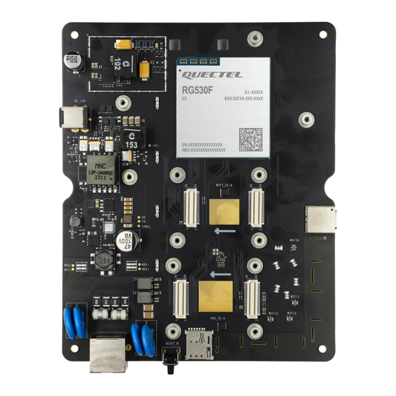
5G Module Series Product Overview 2.1. Top and Bottom Views The size of 5GDM0x-EV EVB is 130 mm × 160 mm, and the top and bottom views are shown as below: Figure 1: Top View 5GDM0x-EV_EVB_User_Guide 9 / 46... - Page 11 5G Module Series Figure 2: Bottom View 5GDM0x-EV_EVB_User_Guide 10 / 46...
-
Page 12: Component Placement
5G Module Series 2.2. Component Placement 130 mm 3V8_mmWAVE PWRKEY S1301 3V8_mmWAVE_IN PWRKEY mmWave Interface USB_BOOT ANT8 ANT9 QTM0 QTM1 USB_BOOT VBAT REG_1V8 J1202 J0601 VBAT QTM3 REG_3V3 USB_SWITCH QTM2 VREG_1V9 J1808 J1810 ANT_GNSS J1901 D1310 PWR_LED J1807 ANT3 PS_HOLD Sub6_LED D1307 ANT2... - Page 13 5G Module Series 130 mm J0401 DC_12V MODULE SEC+ SEC- Wi-Fi_TE-A J1201 J0701 J0702 POE_PART Type-C SYNCL MX2+ MX4+ MX1+ MX3+ J1902 ANT_WIFI0 PHY_TE-A J1001 J1002 J1903 ANT_WIFI1 RJ45 J1904 J1905 (U)SIM ANT_WIFI2 ANT_WIFI3 RESET_N J1101 S1302 J1701 Figure 4: Bottom View for Component Placement 5GDM0x-EV_EVB_User_Guide 12 / 46...
- Page 14 5G Module Series Table 2: Components & Functions Components RefDes. Description Implementation ⚫ DC power supply: 12–14 V ⚫ Power Supply J0401 Power jack on the EVB Typical supply voltage: +12 V/ Reset button(Push button) RESET S1302 Reset the module Used to reset the module ⚫...
- Page 15 5G Module Series mmWave J0601 mmWave connector mmWave interface Interface Module U0201 Module interface Module J1902, Wi-Fi ⚫ J1903, Reserved Antenna Wi-Fi antenna connector ⚫ J1904, 4 Wi-Fi antenna connectors Interfaces J1905 J1801, J1803, J1804, Sub-6 J1805, Antenna Sub-6 antenna connector 8 Sub-6 antenna connectors J1806, Interfaces...
-
Page 16: Kit Accessories & Assembly
3.1. Accessories Assembly This chapter will be offered in the next version. 3.2. Accessories List All accessories of the 5GDM0x-EV EVB kit are listed as below. Please contact the supplier if there is something missing. Table 3: Accessories List Items... - Page 17 5G Module Series ⚫ USB driver ⚫ Driver disk QUD driver and UDE driver ⚫ Related tools for modules Memory 8 GB U-disk Including module’s related documents, tools & drivers etc. USB Driver Options PHY TE-A QCA8081-TE-A/AQR113-TE-A Wi-Fi TE-A WCN6856-TE-A (Optional) The power FPC transmits power and control signal from the EVB to RA530T mmWave interface...
-
Page 18: Application Interfaces
5G Module Series Application Interfaces This chapter describes the hardware interfaces of the 5GDM0x-EV EVB, as listed below: ⚫ Power supply ⚫ USB interface ⚫ (U)SIM card interface ⚫ interface* ⚫ Status indicators ⚫ Module interface ⚫ PHY TE-A interfaces* ⚫... - Page 19 5G Module Series The following figures show the simplified power supply block diagram of the EVB. DC_12V 12 V 3.8 V DC/DC Module Figure 5: Block Diagram of EVB Power Supply Figure 6: EVB Power Supply Interface If the power jack is used for power supply, the power plug design of the adapter is shown as below: Inner contact Outer contact Figure 7: Power Plug Design...
-
Page 20: Usb Interface
5G Module Series 4.2. USB Interface The EVB provides a USB 3.1/2.0 Type-C interface and supports SuperSpeed (10 Gbps) high-speed (480 Mbps) and full-speed (12 Mbps) for connection with a host device, as shown in Figure 8 and Figure 9. This USB interface is used for AT command communication, data transmission, GNSS NMEA sentences output, software debugging and firmware upgrade. - Page 21 5G Module Series Type-C cable Figure 9: USB Interface Connection ⚫ When J1202 of USB_SWITCH is connected to REG_3V3, USB is connected to main UART, debug UART and USB 3.1 only. ⚫ When J1202 of USB_SWITCH is not connected to REG_3V3, USB is connected to USB 2.0 and USB 3.1.
-
Page 22: U)Sim Card Interface
5G Module Series 4.3. (U)SIM Card Interface The EVB has a 7-pin push-push type (U)SIM card (1.8/2.95 V) interfaces which support 1.8/2.95 V (U)SIM card. Table 7: Description of (U)SIM Card Interfaces RefDes. Description J1101 (U)SIM card connector The following figure shows a simplified connector schematic for this connector. Push-Push Module USIM_VDD... - Page 23 5G Module Series The figure and table below illustrate the pin assignment and definition of (U)SIM card connector J1101. Figure 11: Pin Assignment of (U)SIM Card Connector J1101 Table 8: Pin Definition of J1101 Pin No. Pin Name Description USIM_VDD U(SIM) card power supply, provided by module USIM_RST U(SIM) card reset...
- Page 24 5G Module Series 4.4. LAN Interface* The EVB provides a LAN interface to connect with PC. The following figure shows the location of the LAN connector. Table 9: Description of LAN Interface RefDes. Description J1701 Connected to PC with LAN cable Users can set the RG530F series to PCIe RC mode through LAN interface.
-
Page 25: Status Indicators
5G Module Series 4.5. Status Indicators There are four status indication LEDs on the EVB. The following figure shows the positions of these LED indicators. Table 10: Description of Status Indication LEDs RefDes. Description Indicates whether the power supply for module is ready. ⚫... -
Page 26: Module Interface
5G Module Series 4.6. Module Interface Module interface is designed to on board of applicable modules. The developer will be able to test the functionalities of the modules easily. Table 11: Description of Module Interface RefDes. Description U0201 Module interface The following figure shows the module on the EVB board. - Page 27 5G Module Series 4.7. PHY TE-A Interfaces* The PHY TE-A interface is designed to accommodate the PHY TE-A (QCA8081 TE-A/AQR113 TE-A). The PHY TE-A is mounted onto and connected to the EVB via BTB connectors (insert as indicated by the arrow to prevent reverse insertion).
- Page 28 5G Module Series Figure 16: Connection Between AQR113 TE-A and EVB 4.8. Wi-Fi TE-A Interfaces* The Wi-Fi TE-A interface is designed to accommodate Wi-Fi TE-A. The TE-A is connected to the EVB via BTB connectors. The interface allows you to test the Wi-Fi function of the module or to develop applications with Wi-Fi function easily.
- Page 29 5G Module Series The following two figures show the connection between WCN6856 TE-A and EVB. BT_UART BT_UART COEX_UART COEX_UART WLAN_EN WLAN_EN BT_EN BT_EN WLAN_SLEEP_CLK WLAN_SLEEP_CLK WLAN_PWR_EN1 WLAN_PWR_EN1 WLAN_PWR_EN2 WLAN_PWR_EN2 WL_LAA_AS_EN WL_LAA_AS_EN WL_PA_MUTING WL_PA_MUTING WL_LAA_RX WL_LAA_RX PCIe PCIe WL_LAA_TX_EN WL_LAA_TX_EN S2_1.2V S2_1.2V WL_TX_EN WL_TX_EN...
-
Page 30: Mmwave Interface
5G Module Series 4.9. mmWave interface The mmWave interface is connected to the EVB via connector and flexible flat cable. The antennas are connected from module to mmWave interface. The interface allows developers to test the mmWave function of the module or to develop applications with mmWave function easily. Table 14: Description of mmWave Interface RefDes. - Page 31 5G Module Series RA530T TE-A J0301 Flexible Flat Cable J0601 5GDM01-EV Figure 20: Connection Between RA530T and EVB 5GDM0x-EV_EVB_User_Guide 30 / 46...
-
Page 32: Antenna Interfaces
5G Module Series Figure 21: Antenna Connection Between RA530T and Module 4.10. Antenna Interfaces The EVB includes three type antenna interfaces: Wi-Fi antennas, Sub-6 antennas, GNSS antenna. Table 15: Wi-Fi, Sub-6 and GNSS Antenna Interfaces Antenna Types RefDes. Description ⚫ Reserved Wi-Fi Antenna Interfaces J1902, J1903, J1904, J1905... -
Page 33: Switch And Buttons
5G Module Series 4.11. Switch and Buttons The EVB includes two buttons & one switch , as shown in the following table and figures: Table 16: Description of Buttons RefDes. Description ⚫ Power key (push button) reserved S1301 ⚫ Used to turn ON/OFF the module ⚫... - Page 34 5G Module Series S1302 Reset key Figure 22: Power Key and Reset Table 17: Description of Switch RefDes. Description ⚫ USB_SWITCH not to REG_3V3: USB 2.0 and USB 3.1 ⚫ USB_SWITCH to REG_3V3: main UART, debug UART and USB 3.1 only J1202 ⚫...
-
Page 35: Test Points
5G Module Series 4.12. Test Points The EVB provides test points which help you obtain the corresponding waveforms of some signals. The following figures show the details of all test points. TP0406 TP0610 TP0405 TP1304 TP0611 TP0404 TP0602 TP0603 TP0604 TP0601 TP0608 TP1303... - Page 36 5G Module Series USB_TEST_POINTS UART_TEST_POINTS Figure 25: Test Points of USB and UART 5GDM0x-EV_EVB_User_Guide 35 / 46...
- Page 37 5G Module Series TP1603 TP1602 SEC- TP1617 TP1618 TP1620 TP1703 TP1701 TP1702 TP1704 Figure 26: Test Points of POE SEC- TP0909 TP0908 QPS615 TP1001 (U)SIM RESET Figure 27: Test Points of QPS615 (U)SIM and Reset 5GDM0x-EV_EVB_User_Guide 36 / 46...
- Page 38 5G Module Series Table 18: Definition of Test Points Power and Power Key and mmWAVE Pin Name Reference Test Points Description TP0405/TP0406/TP0603 /TP0604 Ground TP0401/ TP1304/TP1306/ VBAT_3V8 TP0403/TP0404 3.8 V power supply USB_BOOT TP1301 Emergency download DC_12V TP0402 DC 12 V OUT POE_12V TP1614 POE 12 V OUT...
- Page 39 5G Module Series USB_CC2 TP1205 CC2 pin of the USB CTS_3V3 TP1406 CTS pin is 3.3 V UART_RXD TP1402 The RXD of the main UART 1.8 V UART_TXD TP1401 The TXD of the main UART 1.8 V DBG_RXD TP1404 The RXD of the debug UART 1.8 V DBG_TXD TP1403 The TXD of the debug UART 1.8 V...
- Page 40 5G Module Series JTAG_TMS TP0905 JTAG_TCK TP0904 JTAG_TDO TP0903 USIM_PRESENT TP1101 Hot plug of the (U)SIM USIM_VDD TP1105 VDD of the (U)SIM USIM_RESET TP1104 Reset of the (U)SIM USIM_DATA TP1102 Data of the (U)SIM USIM_CLK TP1103 CLK of the (U)SIM RESET_N TP1305 Reset key of the module...
-
Page 41: Operation Procedures
5G Module Series Operation Procedures This chapter introduces how to use the 5GDM0x-EV EVB for testing and evaluation of applicable modules. Before the procedures below, please ensure modules and the EVB are correctly assembled. 5.1. Turn On the Module 1. Insert a (U)SIM card into the (U)SIM card connector (J1101) on the EVB. -
Page 42: Communication Via Usb Interface Of Uart And Usb 3.1 Only
5G Module Series Install and then use QCOM provided by Quectel to realize the communication between the module and the PC. The following figure shows the COM Port Setting of QCOM: select the correct “COM Port” (USB AT Port, which is shown in figure above) and set correct “Baudrate” (e.g. 115200 bps). For more details about QCOM usage and configuration, see document [2]. -
Page 43: Firmware Upgrade
5G Module Series Figure 31: QCOM Configuration Under Main UART Port Configure AT Command Window, set correct baud rate (such as 115200 bps) and COM number which can be checked by the Device Manager on PC, then the Debug UART will output log. Figure 32: QCOM Configuration Under Debug UART Port 5.4. -
Page 44: Normal Download
5G Module Series 5.4.2. Normal Download Turn on the module according to the procedure in Chapter 5.1. Wait for the USB port to be found in Device Manager of the PC. Figure 33: USB Ports in PC Device Manager Open QFIL and upgrade the firmware. Figure 34: Firmware Download 5GDM0x-EV_EVB_User_Guide 43 / 46... -
Page 45: Reset The Module
5G Module Series 5.5. Reset the Module Reset is only used in case of emergency or abnormality. For example, the software fails to respond for more than 5 seconds due to some serious problems. Press the button S1302 for at least 500 ms and then release it to reset the module. Please note that this operation may cause loss of information in the memory as the module will be initialized after the resetting. -
Page 46: Appendix References
5G Module Series Appendix References Table 19: Related Documents Document Name [1] Quectel_List_of_EVB_Applicable_Modules [2] Quectel_Windows_USB_Driver(Q)_NDIS_Installation_Guide [3] Quectel_QCOM_User_Guide [4] Quectel_QFlash_User_Guide Table 20: Terms and Abbreviations Abbreviation Description Board to Board Cluster Communication Port Direct Current Digital Input Digital Output Evaluation board Evaluation Board Flexible Printed Circuit Ground... - Page 47 5G Module Series Light Emitting Diode Local Area Network mmWave Millimeter wave Not Connected Over Voltage Protection Personal Computer Printed Circuit Board Physical Layer Power Output Power Over Ethernet Power Sourcing Equipment Radio Frequency Register Jack Subscriber Identity Module UART Universal Asynchronous Receiver &...
Need help?
Do you have a question about the 5GDM0x-EV and is the answer not in the manual?
Questions and answers