
Related Manuals for Quectel RMU500-EKNM


Summary of Contents for Quectel RMU500-EKNM
- Page 1 RMU500-EKNM EVB Kit User Guide 5G Module Series Version: 1.0 Date: 2021-10-13 Status: Released...
- Page 2 5G Module Series At Quectel, our aim is to provide timely and comprehensive services to our customers. If you require any assistance, please contact our headquarters: Quectel Wireless Solutions Co., Ltd. Building 5, Shanghai Business Park Phase III (Area B), No.1016 Tianlin Road, Minhang District, Shanghai...
- Page 3 Except as otherwise set forth herein, nothing in this document shall be construed as conferring any rights to use any trademark, trade name or name, abbreviation, or counterfeit product thereof owned by Quectel or any third party in advertising, publicity, or other aspects.
-
Page 4: Safety Information
Manufacturers of the cellular terminal should notify users and operating personnel of the following safety information by incorporating these guidelines into all manuals of the product. Otherwise, Quectel assumes no liability for customers’ failure to comply with these precautions. -
Page 5: About The Document
5G Module Series About the Document Revision History Version Date Author Description 2021-09-27 Albert XU Creation of the document 2021-10-13 Albert XU First official released RMU500-EKNM_EVB_Kit_User_Guide 4 / 30... -
Page 6: Table Of Contents
5G Module Series Contents Safety Information ............................3 About the Document ........................... 4 Contents ............................... 5 Table Index ..............................6 Figure Index ..............................7 Introduction ............................8 1.1. Applicable Modules ........................8 General Overview ..........................9 2.1. Key Features ..........................9 2.2. - Page 7 5G Module Series Table Index Table 1: Applicable Modules ........................8 Table 2: Key Features ..........................9 Table 3: Interfaces of the EVB ........................10 Table 4: List of Accessories ........................12 Table 5: Pin Definition of J401 ........................17 Table 6: Description of Status Indicator LEDs ...................
- Page 8 5G Module Series Figure Index Figure 1: Component Placement of the EVB (Top View) ................10 Figure 2: EVB Top View ..........................11 Figure 3: EVB Bottom View ........................11 Figure 4: EVB Power Supply Interfaces ..................... 13 Figure 5: M.2 Connector of the EVB ......................14 Figure 6: USB Connector ...........................
-
Page 9: Introduction
5G Module Series Introduction This document introduces the EVB kit, RMU500-EKNM, for Quectel 5G M.2 modules, which is an assistant tool kit for engineers to develop and test the modules. 1.1. Applicable Modules Table 1: Applicable Modules Module Series Models... -
Page 10: General Overview
5G Module Series General Overview Quectel provides the RMU500-EKNM EVB kit for engineers to develop applications based on 5G M.2 modules and to test basic functionalities of the applicable modules. 2.1. Key Features Table 2: Key Features Features Description Power Supply DC power supply: +5 V/ 2.5 A for the EVB... -
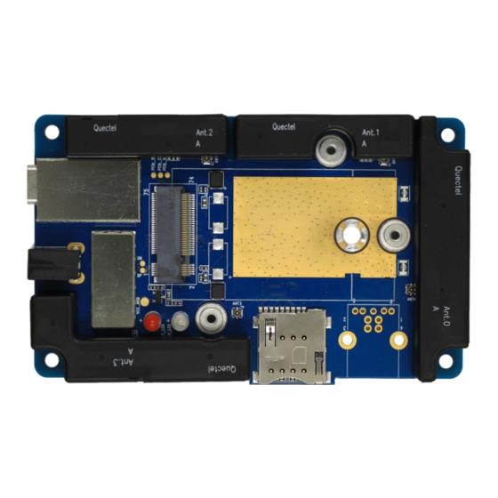
Page 11: Component Placement Of The Evb
5G Module Series 2.2. Component Placement of the EVB J201 J301 Shielding Cover J101 Shielding Cover D104 D107 Type-B J401 Figure 1: Component Placement of the EVB (Top View) Table 3: Interfaces of the EVB Interfaces Reference Designator Description The power jack on the EVB Power Supply J101 (Power Jack) Typical supply voltage: +5 V/ 2.5 A... -
Page 12: Top And Bottom View Of The Evb
5G Module Series 2.3. Top and bottom View of the EVB The following figure shows the top view of the EVB. Figure 2: EVB Top View The following figure shows the bottom view of the EVB. Figure 3: EVB Bottom View RMU500-EKNM_EVB_Kit_User_Guide 11 / 30... -
Page 13: Evb Kit Accessories
Used to clamp the module, antennas and heatsink on the EVB NOTE NONE of the applicable 5G M.2 modules are included as accessories of the RMU500-EKNM EVB kit. RF cables, heatsink, soft silicone pad, and screws are included as accessories. -
Page 14: Interface Application
5G Module Series Interface Application This chapter describes the following hardware interfaces of RMU500-EKNM: ⚫ Power supply (J101/J301) ⚫ M.2 interface (J201) ⚫ USB interface (J301) ⚫ (U)SIM interface (J401) ⚫ RF cables and antennas It also provides information about the status indicator LEDs (D104/D107) to help you use the EVB. -
Page 15: Interface (J201)
5G Module Series 3.2. M.2 Interface (J201) The M.2 connector is designed to accommodate the module. The following figure shows the M.2 connector on the EVB. Figure 5: M.2 Connector of the EVB RMU500-EKNM_EVB_Kit_User_Guide 14 / 30... -
Page 16: Usb Interface (J301)
5G Module Series 3.3. USB Interface (J301) The EVB provides a Type-C USB connector (J301) for the connection with a host. Type-C USB can be used for data transmission. Also, it can be used as power supply interface to power on the EVB. J301 USB Connector Figure 6: USB Connector... -
Page 17: U)Sim Interface (J401)
5G Module Series One end of Type-A is connected to the computer, and, when necessary (e.g., when power supply from the Type-A connected to the PC is inadequate), the other end is connected to the auxiliary power supply. 3.4. (U)SIM Interface (J401) The EVB has an 8-pin push-push type (U)SIM card (1.8/2.95 V) connector (J401). -
Page 18: Status Indicator (D104/D107)
5G Module Series Table 5: Pin Definition of J401 Pin No. Pin Name Function USIM_VDD (U)SIM card power supply USIM_RST (U)SIM card reset USIM_CLK (U)SIM card clock RESERVED Not connected Ground Not connected USIM_DATA (U)SIM card data RESERVED Not connected USIM_DET (U)SIM card detection 3.5. -
Page 19: Rf Cables And Antennas
5G Module Series Table 6: Description of Status Indicator LEDs Reference Designator Description Power indicator, indicating whether the module’s power supply is ready. D104 (POWER_LED) Light on: power on Light off: power off RF status indicator for the module. D107 (WWAN_LED) Light on: RF function is enabled Light off: RF function is disabled 3.6. -
Page 20: Antenna Efficiency
Figure 12: Antenna Efficiency at 700–960 MHz and 1.7–6 GHz Figure 13: Antenna Efficiency at 1.7–6 GHz NOTE All measurements are done for the antennas of the RMU500-EKNM EVB kit with Agilent E5071C ENA network analyzer and OTA chamber. RMU500-EKNM_EVB_Kit_User_Guide... -
Page 21: Antenna Specification
5G Module Series 3.6.3. Antenna Specification The specification of antennas is provided in the following table. Table 7: Antenna Specification Antenna Specification Frequency Range: 0.7–6 GHz Ant 0 Input Impedance: 50 Ω Frequency Range: 1.7–6 GHz Ant 1 Input Impedance: 50 Ω Frequency Range: 1.7–6 GHz Ant 2 Input Impedance: 50 Ω... - Page 22 5G Module Series Figure 15: RM500Q-AE/RM502Q-AE RF Cable Sequence NOTE 1. Ant 0–3 have been assembled on the EVB to prevent damage during transportation. 2. The RM500Q-CN module, which supports GNSS L1 + L5, cannot support L5 in this case because the frequency range of Ant 1 is 1.7–6 GHz.
-
Page 23: Evb Operation Procedures
5G Module Series EVB Operation Procedures This chapter introduces how to assemble and use the RMU500-EKNM EVB kit to test and evaluate the module. 4.1. Component Assembling Steps Please follow these steps to assemble the product. Step 1: Remove the antennas one by one, and keep the antennas and screws. - Page 24 5G Module Series Step 2: Attach the thermal conductive pad, insert the module, and lock the screw. Figure 17: Assembling (Step Two) Step 3: Insert four RF cables. There are two RF cable assembling methods when the EVB kit is used with different modules.
- Page 25 5G Module Series Figure 19: RM500Q-CN/RM500Q-GL RF Cable Assembly Figure 20: RM500Q-AE/RM502Q-AE RF Cable Assembly RMU500-EKNM_EVB_Kit_User_Guide 24 / 30...
- Page 26 5G Module Series Step 4: Place the heatsink on the module and tighten the screws. Figure 21: Assembling (Step Four) Step 5: Assemble the antenna in turn and tighten the screws. Figure 22 Assembling (Step Five) RMU500-EKNM_EVB_Kit_User_Guide 25 / 30...
-
Page 27: Turn On The Module
5G Module Series Then, the assembly is finished. The assembled EVB kit is shown below. Figure 23: Assembled EVB Kit 4.2. Turn on the Module Finish the assembling steps above. Insert a (U)SIM card into the (U)SIM card connector on the EVB. Insert the USB cable (Type-C to dual Type-A). -
Page 28: Firmware Upgrade
Install and open the firmware upgrade tool, QFlash, on the PC and then turn on the module according to the procedures in Chapter 4.2. Click the “COM Port” dropdown list and select the Port No. corresponding to “Quectel USB DM Port” in the Device Manager. -
Page 29: Turn Off The Module
5G Module Series Figure 26: Configurations for Firmware Upgrade For more details about QFlash usage and configuration, see document [3]. 4.5. Turn Off the Module There are two methods to turn off the module. ⚫ Hardware method: the module will be turned off after the power supply is disconnected. ⚫... -
Page 30: Appendix References
5G Module Series Appendix References Table 8: Related Documents Document Name [1] Quectel_LTE&5G_Windows_USB_Driver_Installation_Guide [2] Quectel_QCOM_User_Guide [3] Quectel_QFlash_User_Guide [4] Quectel_RG50xQ&RM5xxQ_Series_AT_Commands_Manual Table 9: Terms and Abbreviations Abbreviation Description Communication Port Direct Current Digital Input Digital Output Evaluation Board Ground Input/Output Light Emitting Diode Not Connected Personal Computer Printed Circuit Board... - Page 31 5G Module Series Power Output Radio Frequency Secure Digital Subscriber Identity Module UART Universal Asynchronous Receiver & Transmitter Universal Serial Bus (U)SIM (Universal) Subscriber Identity Module RMU500-EKNM_EVB_Kit_User_Guide 30 / 30...
Need help?
Do you have a question about the RMU500-EKNM and is the answer not in the manual?
Questions and answers