
Related Manuals for Quectel RMU500-EK


Summary of Contents for Quectel RMU500-EK
- Page 1 RMU500-EK User Guide 5G Module Series Version: 1.0 Date: 2020-11-23 Status: Released www.quectel.com...
- Page 2 To the maximum extent permitted by law, Quectel excludes all liability for any loss or damage suffered in connection with the use of the functions and features under development, regardless of whether such loss or damage may have been foreseeable.
- Page 3 RMU500-EK User Guide Copyright The information contained here is proprietary technical information of Quectel wireless solutions co., ltd. Transmitting, reproducing, disseminating and editing this document as well as using the content without permission are forbidden. Offenders will be held liable for payment of damages. All rights are reserved in the event of a patent grant or registration of a utility model or design.
-
Page 4: About The Document
5G Module Series RMU500-EK User Guide About the Document Revision History Version Date Author Description Tom TANG/ 2019-12-19 Creation of the document Shaky LIN Tom TANG/ 2020-11-23 First official release Shaky LIN RMU500-EK_User_Guide 3 / 28... -
Page 5: Table Of Contents
5G Module Series RMU500-EK User Guide Contents About the Document ........................... 3 Contents ............................... 4 Table Index ..............................5 Figure Index ..............................6 Introduction ............................7 1.1. Safety Information ........................7 General Overview ..........................9 2.1. Key Features ........................... 9 2.2. - Page 6 5G Module Series RMU500-EK User Guide Table Index Table 1: Key Features ..........................9 Table 2: Interfaces and Functions of the EVB ................... 10 Table 3: Accessories List ........................... 11 Table 4: Pin Definition of J401 ........................16 Table 5: Description of Status Indicator LEDs ................... 17 Table 6: Antenna Specification ........................
- Page 7 5G Module Series RMU500-EK User Guide Figure Index Figure 1: Component Placement of the EVB (Top View) ................10 Figure 2: EVB Top View ..........................11 Figure 3: EVB Power Supply Interfaces ..................... 13 Figure 4: M.2 Connector on the EVB ......................14 Figure 5: USB Connector ...........................
-
Page 8: Introduction
Manufacturers of the cellular terminal should notify users and operating personnel of the following safety information by incorporating these guidelines into all manuals of the product. Otherwise, Quectel assumes no liability for customers’ failure to comply with these precautions. - Page 9 5G Module Series RMU500-EK User Guide The cellular terminal or mobile contains a transceiver. When it is ON, it receives and transmits radio frequency signals. RF interference can occur if it is used close to TV sets, radios, computers or other electric equipment.
-
Page 10: General Overview
5G Module Series RMU500-EK User Guide General Overview Quectel supplies RMU500-EK for designers to develop applications based on RM500Q-GL module and to test basic functionalities of it. 2.1. Key Features The following table describes the detailed features of RMU500-EK. Table 1: Key Features... -
Page 11: Component Placement Of The Evb
5G Module Series RMU500-EK User Guide 2.2. Component Placement of the EVB J301 Shielding Cover J101 Shielding Cover D104 D107 Type-B J401 Figure 1: Component Placement of the EVB (Top View) Table 2: Interfaces and Functions of the EVB Interfaces... -
Page 12: Top View Of The Evb
5G Module Series RMU500-EK User Guide 2.3. Top View of the EVB Top view of the EVB is exhibited by the figure below. Figure 2: EVB Top View 2.4. EVB Kit Accessories All accessories for the EVB are listed in the following table. - Page 13 RMU500-EK User Guide Silicone Silicone soft pad Heatsink Black anodized AL6063 Including the related documents, tools, and USB Flash Drive drivers for the module and RMU500-EK. Used to clamp the module, antennas and Screws heatsink on the EVB RMU500-EK_User_Guide 12 / 28...
-
Page 14: Components/Interfaces
5G Module Series RMU500-EK User Guide Components/Interfaces 3.1. Components/Interfaces of the EVB This chapter mainly describes the application of the following EVB interfaces: ⚫ Power supply ⚫ M.2 interface ⚫ USB interface ⚫ (U)SIM interface ⚫ RF cables and antennas It also provides information about the status indicator LEDs to help you use the EVB. -
Page 15: Interface (J201)
5G Module Series RMU500-EK User Guide 3.1.2. M.2 Interface (J201) The M.2 connector is designed to accommodate the module. The following figure shows the M.2 connector on RMU500-EK.. Figure 4: M.2 Connector on the EVB 3.1.3. USB Interface (J301) The EVB provides a Type-C USB connector J301 for the connection with a host. -
Page 16: U)Sim Interface (J401)
5G Module Series RMU500-EK User Guide Figure 6: Connection Between PC and EVB One end of Type-A is connected to the computer, and, when necessary (e.g. when power supply from the Type-A connected to the PC is inadequate), the other end is connected to the auxiliary power supply. - Page 17 5G Module Series RMU500-EK User Guide The figure and table below illustrate the pin assignment and pin definition of (U)SIM card connector J401. Figure 8: Pin Assignment of (U)SIM Card Connector J401 Table 4: Pin Definition of J401 Pin No.
-
Page 18: Status Indicator (D104/D107)
5G Module Series RMU500-EK User Guide 3.1.5. Status Indicator (D104/D107) The EVB provides two status indicator LEDs D104 and D107. The following figure shows the positions of these indicators. Figure 9: Status Indicators Table 5: Description of Status Indicator LEDs... -
Page 19: Rf Cables And Antennas
5G Module Series RMU500-EK User Guide 3.1.6. RF Cables and Antennas 3.1.6.1. Antenna Design The following figure is a typical reference design for the antennas. Module Figure 10: Reference Design for Antennas The matching circuit is composed of C1, C2 and R1 for antenna impedance modification. By default, the value of R1 is 0 Ω, while C1 and C2 are not mounted. -
Page 20: Antenna Specification
RMU500-EK User Guide Figure 12: Antenna Efficiency at 1.7–6 GHz NOTE All measurements are done for the antenna mounted on RMU500-EK PCB with VNA Agilent 5071C and OTA chamber. 3.1.6.3. Antenna Specification The specification of antennas are provided in the following table. -
Page 21: Component Assembling Steps
5G Module Series RMU500-EK User Guide 3.2. Component Assembling Steps Please follow these steps to assemble the product. Step 1: Insert four RF cables. Figure 13: Assembling Step 1 RMU500-EK_User_Guide 20 / 28... - Page 22 5G Module Series RMU500-EK User Guide Step 2: Stick the thermal pad, insert the module into the M.2 connector and tighten the screw. Figure 14: Assembling Step 2 Step 3: Connect the EVB and the module with RF cables as illustrated by the figure below.
- Page 23 5G Module Series RMU500-EK User Guide Step 4: Place the heatsink on the module and tighten the screws. Figure 16: Assembling Step 4 Step 5: Install the antennas in turn and tighten the screws. Figure 17: Assembling Step 5 RMU500-EK_User_Guide...
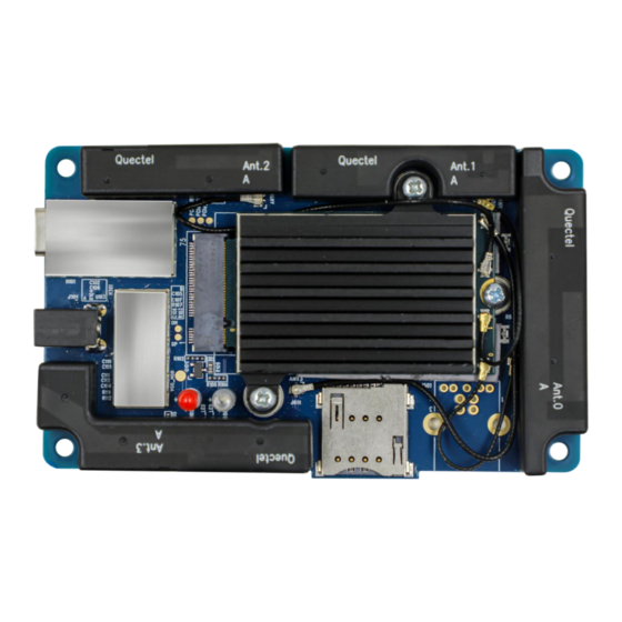
- Page 24 5G Module Series RMU500-EK User Guide Step 6: Assembling finished. Figure 18: Assembling Step 6 RMU500-EK_User_Guide 23 / 28...
-
Page 25: Evb Operation Procedures
PC to install the USB driver. For details about USB driver installation, see document [1]. Figure 19: USB Ports Install and then use the tool, QCOM, provided by Quectel to realize the communication between the module and the PC. -
Page 26: Firmware Upgrade
Install and open the firmware upgrade tool, QFlash, on the PC and then turn on the module according to the procedures in Chapter 4.1. Click the “COM Port” dropdown list and select the Port No. corresponding to “Quectel USB DM Port”. Click the “Load FW Files” button and choose the firmware package. -
Page 27: Turn Off The Module
5G Module Series RMU500-EK User Guide For more details about QFlash usage and configuration, see document [3]. 4.4. Turn Off the Module There are two methods to turn off the module. ⚫ Hardware method: the module will be turned off after the USB cable is disconnected. -
Page 28: Appendix References
5G Module Series RMU500-EK User Guide Appendix References Table 7: Related Documents Document Name Description Quectel_LTE&5G_Windows_USB_Driver Installation guide of USB driver for LTE&5G modules _Installation_Guide on Windows system Quectel_QCOM_User_Guide User guide for QCOM tool Quectel_QFlash_User_Guide User guide for QFlash tool AT commands manual for RM500Q-GL, RM500Q-AE, Quectel_RG50xQ&RM5xxQ_Series_AT... - Page 29 5G Module Series RMU500-EK User Guide Personal Computer Printed Circuit Board Power Output Radio Frequency Secure Digital Subscriber Identity Module UART Universal Asynchronous Receiver & Transmitter Universal Serial Bus (U)SIM (Universal) Subscriber Identity Module RMU500-EK_User_Guide 28 / 28...
Need help?
Do you have a question about the RMU500-EK and is the answer not in the manual?
Questions and answers