
Related Manuals for SMC Networks JMHZ2-8D


Summary of Contents for SMC Networks JMHZ2-8D
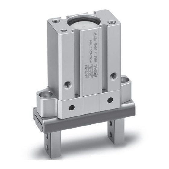
- Page 1 Doc. no.MH∗-OMX0002 PRODUCT NAME AIR GRIPPER MODEL / Series / Product Number JMHZ2-8D JMHZ2-12D JMHZ2-16D JMHZ2-20D...
-
Page 2: Table Of Contents
Contents Safety Instructions 1. Product Specifications 1-1. Specifications 2. Operating Method / Operation 2-1. Design 2-2. Selection 2-3. Installation 2-4. Air supply 2-5. Piping 2-6. Operating environment 2-7. Lubrication 3. Maintenance 3-1. Precautions 3-2. Disassembly drawing 3-3. Finger assembly set replacement procedure 3-4. - Page 3 Safety Instructions These safety instructions are intended to prevent hazardous situations and/or equipment damage. These instructions indicate the level of potential hazard with the labels of “Caution,” “Warning” or “Danger.” They are all important notes for safety and must be followed in addition to International Standards (ISO/IEC) , and other safety regulations.
- Page 4 Safety Instructions Caution The product is provided for use in manufacturing industries. The product herein described is basically provided for peaceful use in manufacturing industries. If considering using the product in other industries, consult SMC beforehand and exchange specifications or a contract if necessary. If anything is unclear, contact your nearest sales branch.
-
Page 5: Product Specifications
1. Product Specifications 1-1 Specifications Specifications Model JMHZ2-8D JMHZ2-12D JMHZ2-16D JMHZ2-20D Bore size (mm) Fluid Operating pressure [MPa] 0.15 to 0.7 0.1 to 0.7 -10 to 60 Ambient and fluid temperature ( 0.01 Repeatability (mm) Maximum operating frequency (c.p.m.) Lubrication... -
Page 6: Operating Method / Operation
2. Operating Method / Operation 2-1 Design ! Warning 1. The product is designed for use only in compressed air systems. Do not operate at pressures or temperatures, etc., beyond the range of the specifications, as this can cause damage or malfunction of the cylinder and other equipment. (Refer to the specifications.) Please contact SMC if using fluids other than compressed air. -
Page 7: Installation
(3) Select a larger size gripper or used two or more grippers for handling a long and/or large workpiece. 3. Provide a run off space in the attachment when using with a small or thin workpiece. If a runoff space is not provided, gripping becomes unsteady, and it may lead to gripping failure or slippage. - Page 8 How to mount attachment to the finger Make sure to mount the attachments on fingers with the tightening torque in the table below by using bolts, etc., for the female threads on fingers. Max. tightening torque Model Bolt JMHZ2-8 M2.5x0.45 0.31 JMHZ2-12 M2.5x0.45...
- Page 9 ! Caution 1. To mount the attachment to the finger, make sure not to apply undue strain on the finger. Any damage to the gripper may cause malfunction and reduce the accuracy. 2. Avoid external force to the finger. Fingers may be damaged by a continual lateral or impact load. Provide clearance to prevent the workpiece or the attachment from striking against any object at the stroke end.
- Page 10 3. Adjust the gripping point so that an excessive force will not be applied to the fingers when inserting a workpiece. Confirm that the gripper can operate without receiving any shock by testing it in manual operation mode or by low speed operation. Impact load ○...
-
Page 11: Air Supply
2-4 Air supply ! Warning 1. Please contact SMC when using the product in applications other than with compressed air. 2. Compressed air containing a large amount of condensate can cause malfunction of pneumatic equipment. An air dryer or water separator should be installed upstream from filters. -
Page 12: Operating Environment
2-6. Operating environment ! Warning 1. Do not use in an environment where corrosive gases, chemicals, sea water, water or steam are present. 2. Do not use in direct sunlight. 3. Do not operate in a location subject to vibration or impact. 4. -
Page 13: Maintenance
3. Maintenance 3-1. Precautions ! Warning 1. Maintenance should be performed according to the procedure indicated in the Operation Manual. If handled improperly, malfunction and damage of machinery of equipment may occur. 2. If handled improperly, compressed air can be dangerous. Assembly, handling, repair and element replacement of pneumatic systems should be performed by a knowledgeable and experienced person. -
Page 14: Disassembly Drawing
3-2 Disassembly drawing Finger assembly Hexagon Tightening wrench torque (Nominal) (N・m) ø 8 0.18 ø 12 0.18 ø 16 0.36 ø 20 0.63 Lever Hexagon socket head cap screws. Body B Lever shaft Rod cover Seal kit Gasket Seal support Rod seal Piston seal Piston assembly... -
Page 15: Finger Assembly Set Replacement Procedure
3-3. Finger assembly set replacement procedure (1) Direction of the body of the drawing below is recommended for mounting the finger assembly to the body. Note) For ø8, use a hexagon wrench with a ball end. Mount the finger assembly and the Body A with care so that the guide bolts do not interfere with the Body A. -
Page 16: Seal Replacement Procedure
3-4. Seal replacement procedure (1) Loosen the guide bolts and remove the finger assembly. Hexagon socket head cap screws. (2) Loosen hexagon socket head cap screws, Body B and then remove them from the Body A. Body A Guide bolt (3) Push the seal support so that the rod cover comes out of the Body B end surface. -
Page 17: Construction / Parts List, Seal List
3-5. Construction / Parts list, seal list Components Parts description Description Body A Lever shaft Piston assembly Seal support Lever Rod cover Guide Steel ball Rod seal Finger Piston seal Roller stopper Gasket Body B Replacement parts Description JMHZ2-8 JMHZ2-12 JMHZ2-16 JMHZ2-20 Main part... - Page 18 Revision history 4-14-1, Sotokanda, Chiyoda-ku, Tokyo 101-0021 JAPAN Tel: + 81 3 5207 8249 Fax: +81 3 5298 5362 https://www.smcworld.com Note: Specifications are subject to change without prior notice and any obligation on the part of the manufacturer. © 2011 SMC Corporation All Rights Reserved...
Need help?
Do you have a question about the JMHZ2-8D and is the answer not in the manual?
Questions and answers