Table of Contents
Advertisement
Quick Links
56-JSXF-TF2Z575EN
ORIGINAL INSTRUCTIONS
Instruction Manual
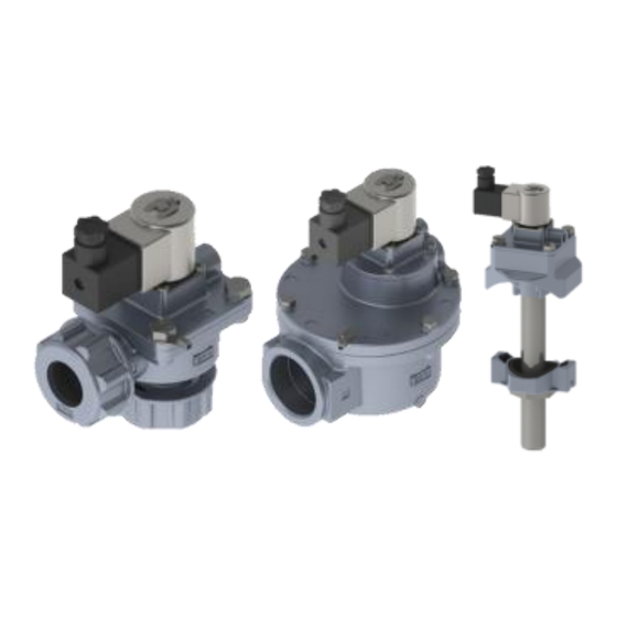
Solenoid Operated Pulse Valve for Dust
Collector
56-JSXF(E/F/H) Series
Ex classification:
II 3 G Ex ec h IIB T3 Gc
II 3 D Ex h tc IIIB T161°C Dc
-20°C ≤ Ta ≤ +60°C
Ambient temperature:
Certificate reference:
SMC 21.0041 X
'X' Special conditions for safe use apply, see section 1.2.
The intended use of this product is to provide a pulse of air in dust
collector and similar systems.
1 Safety Instructions
1.1 General safety instructions
These safety instructions are intended to prevent hazardous situations
and/or equipment damage. These instructions indicate the level of
potential hazard with the labels of "Caution," "Warning" or "Danger."
They are all important notes for safety and must be followed in addition
to International Standards (ISO/IEC)
*1)
, and other safety regulations.
*1)
ISO 4414: Pneumatic fluid power - General rules relating to systems.
ISO 4413: Hydraulic fluid power - General rules relating to systems.
IEC 60204-1: Safety of machinery - Electrical equipment of machines.
(Part 1: General requirements)
ISO 10218-1: Robots and robotic devices - Safety requirements for
industrial robots - Part 1: Robots.
• Refer to product catalogue, Operation Manual and Handling
Precautions for SMC Products for additional information.
• Keep this manual in a safe place for future reference.
Caution indicates a hazard with a low level of risk which, if
Caution
not avoided, could result in minor or moderate injury.
Warning indicates a hazard with a medium level of risk
Warning
which, if not avoided, could result in death or serious injury.
Danger indicates a hazard with a high level of risk which, if
Danger
not avoided, will result in death or serious injury.
Warning
• Always ensure compliance with relevant safety laws and
standards.
• All work must be carried out in a safe manner by a qualified person in
compliance with applicable national regulations.
• If this equipment is used in a manner not specified by the manufacturer
the protection provided by the equipment may be impaired.
1.2 Special conditions for safe use
Warning
• To avoid the build-up of electrostatic charge, do not mount in areas
subject to electrostatic charging mechanisms and clean only with a
damp cloth and allow to dry naturally.
• The product shall be protected from impacts in compliance with the
applicable explosive atmosphere standards.
• The product must be protected from UV light.
• Do not separate the DIN connector in hazardous locations.
2 Specifications
2.1 Valve specification
Valve construction
Diaphragm Type Pilot Operated
Valve type
Normally closed (N.C.)
JSXFE
Compression fitting
Piping
JSXFF
Direct piping
JSXFH
Tank mounting (immersion)
Port size [inch]
3/4
1
1 1/2
Orifice, ∅ [mm]
JSXFE/F:50
32
40
JSXFH:45
Note 3)
Tank size ANSI [inch]
4, 5
5, 6
6, 8
Fluid
Air
Air filtration [µm]
5 (or less)
Minimum operating pressure differential [MPa]
0.1
Maximum operating pressure differential [MPa]
0.9
Maximum system pressure [MPa]
Fluid temperature [ºC]
-20
Note 4)
to +60
Ambient temperature [ºC]
Flow characteristics
Contact SMC
Response time [ms]
≤33% (MAX ON 1s)
Duty cycle
Minimum operating frequency
1 cycle / 30 days
Maximum operating frequency [Hz]
0.5
Lubrication
Not required
Mounting orientation
Unrestricted
Note 5)
Operating environment
Indoor/Outdoor
Weight
Refer to catalogue
Note 1) Seals and washers included.
Note 2) Valve and piping packed together, not assembled.
Note 3) Only available for JSXFH.
Note 4) Take measures to prevent condensation, freezing or solidification of
impurities etc. The installation of a dryer is recommended to prevent
freezing conditions (e.g. when dew point temperature is high and ambient
temperature low or rate of flow is high).
Note 5) Ensure the product is protected from UV light and rainwater.
2.2 Solenoid specification
Electrical entry
DIN terminal
Coil rated voltage [V, DC]
24
Allowable voltage fluctuation
±10% of rated voltage
Enclosure
IP65
Power consumption [W,DC]
12
≤ 2% of rated voltage
Allowable leakage voltage
Surge voltage suppressor
Varistor
Coil insulation class
B
2.3 Production batch codes
Construction
Production batch codes
Year / Month
Jan Feb Mar Apr May Jun Jul Aug Sep Oct Nov Dec
2022
Ao
AP
AQ AR
AS
AT
AU AV
AW AX
2023
Bo
BP
BQ BR
BS
BT
BU BV
BW BX
...
...
...
...
...
...
...
...
...
...
...
2026
Eo
EP
EQ ER
ES
ET
EU EV
EW EX
Note: The batch code is included on the product label.
2.4 JSXF(E/F/H) port sizes and options
Port size
Model
Tank size
06
10
14
•
•
•
JSXFE
-
•
•
•
JSXFF
-
•
4 Inch
-
-
•
•
5 Inch
-
•
•
6 Inch
JSXFH
-
•
8 Inch
-
-
10 Inch
-
-
-
•
•
•
Silencer
3 Installation
3.1 General
Warning
• Do not install the product unless the safety instructions have been read
Note 1)
and understood.
• The valve is designed for pulse operation. Do not energise the valve
Note 2)
continuously as it can cause oscillation (chattering) of the diaphragm
Note 3)
2
leading to product failure due to the large amount of air consumed
55
causing insufficient air supply on the inlet side. In addition, continuous
Note 3)
energisation may lead to excessive temperature rise. See 2.1 for
8, 10
maximum operating frequency and duty cycle limitations.
• Customer shall ensure that the sudden pulse of air released by the
valve when operated does not generate an ignition source within the
system.
• See 3.3 regarding internal earthing and external bonding.
• Use clean air filtered to 5 µm or less. Filtration to be installed upstream
near to the valve.
Caution
• Use steel tubing for the inlet and outlet piping.
• Do not rely on the valve piping ports to support the piping. Ensure that
the piping is independently supported so that pulling, pressing,
bending or other forces are not applied to the valve body.
• For details regarding pipe sizes, refer to the standard JSXF Series
catalogue.
• Ensure that the air supply is sufficient to meet the high flow demand of
the valve when operated. If the inlet is restricted or the supply tank
capacity is low, then the main valve may oscillate (chatter) due to
pressure drop or insufficient supply.
3.2 Environment
Warning
• Do not use in an environment where corrosive gases, chemicals, salt
water or steam are present.
• The product must be protected from UV light.
• Do not install in a location subject to vibration or impact.
• Do not mount in a location exposed to radiant heat that would result in
temperatures in excess of the product's specifications.
• The valves are certified to Ex category 3GD (Zones 2, 22).
• Do not mount in areas subject to electrostatic charging mechanisms.
• Do not install in locations subject to the accumulation of water.
Exposure to natural weather is not permitted.
• Products compliant with IP65 enclosures are protected against dust
and water, however, these products cannot be used in water.
• Products compliant with IP65 enclosures satisfy the specifications by
mounting each product properly. Be sure to read the Specific Product
Precautions for each product.
3.3 Earthing and Bonding
Warning
Ay
AZ
3.3.1 Internal earthing
By
BZ
An internal earth connection is not required for this 24 VDC, 2-wire
...
...
product. The earth connection facility of the DIN connector has no
Ey
EZ
function. Only pins 1 and 2 (+/-) of the connector shall be wired, see 3.7
for connection diagram.
Warning
3.3.2 External bonding
• An external bonding facility is mandatory for this product. A ring
20
terminal is provided (included in product packaging) for this purpose to
-
be installed using the marked main valve bonnet hexagon bolt, see
-
Fig.6. Locations shown in Fig.1.
• Refer to the disassembly and assembly procedures, 6.2 and 6.3, for
-
mounting the ring terminal.
-
• Use cable with insulated wires, stranded, 4 to 6.64 mm².
• Terminate wire to the ring terminal using an appropriate crimping tool.
-
•
• After crimping, check the crimp by slightly pulling the insulated wire.
• Check valve continuity with external bonding circuit after installation.
•
• Check marked main valve bonnet hexagon bolt tightness periodically,
•
see section 6.1.
3 Installation (continued)
Size 06
Size 10
Bonding terminal
Bonding terminal
Size 14
Size 20
Bonding terminal
Bonding terminal
Fig.1
3.4 Piping
Caution
• Before connecting piping make sure to clean up chips, cutting oil, dust
etc.
• When installing piping or fittings, ensure sealant material does not
enter inside the port. When using seal tape, leave 1.5 to 2 threads
exposed on the end of the pipe/fitting.
• Tighten fittings to the specified tightening torque.
Fitting tightening torque
Tightening torque [N•m]
Connection thread [Rc]
1/4
12 to 14
3/8
22 to 24
1/2
28 to 30
3/4
28 to 30
1
36 to 38
1 1/2
40 to 42
3.5 Valve mounting - JSXFE and JSXFH
3.5.1 JSXFE
Warning
• The compression fitting is used to seal the connection between the
valve and the pipework. Do not rely on the compression fitting to
support the piping as it could become detached. Ensure that inlet and
outlet piping is secured with separate fixings.
Caution
• Mount the valve to fixed metal piping (to ensure correct sealing of the
fitting, do not expose the piping to oil or moisture).
• Insert the piping into the valve body until it stops to prevent
misalignment of the piping in relation to the valve body, see Fig.2.
Washer
Compression nut
Seal
IN
Piping
Compression nut
Fig.2
• Tighten the compression nut sufficiently to prevent nut becoming loose
and leakage occurring. Hand tighten, then secure with a wrench.
Tightening angle after hand-tightening
Size
Wrench tightening angle [°]
3/4 (20A)
90 to 270
1 (25A)
135 to 315
1 1/2 (40A)
150 to 330
Page 1 of 3
Advertisement
Table of Contents

Related Manuals for SMC Networks JSXFE Series


Summary of Contents for SMC Networks JSXFE Series
- Page 1 56-JSXF-TF2Z575EN 2 Specifications 3 Installation 3 Installation (continued) ORIGINAL INSTRUCTIONS 2.1 Valve specification 3.1 General Size 06 Size 10 Valve construction Diaphragm Type Pilot Operated Warning Valve type Normally closed (N.C.) • Do not install the product unless the safety instructions have been read Instruction Manual Note 1) JSXFE...
- Page 2 56-JSXF-TF2Z575EN 3 Installation (continued) 3 Installation (continued) 3 Installation (continued) 6 Maintenance (continued) • The installation shall provide strain relief for the cable close to the • Before performing maintenance, turn off the power supply and be sure 3.5.2 JSXFH Tank hole pitch •...
- Page 3 56-JSXF-TF2Z575EN 6 Maintenance (continued) 6 Maintenance (continued) 8 Product Disposal Port size: 06, 10 Port size: 14 This product shall not be disposed of as municipal waste. Check your 6.4 Replacement parts Main valve position Main valve position Sub-valve position local regulations and guidelines to dispose this product correctly, in order The main valve and sub-valve elements (including O-ring), silencer, and Align the...
Need help?
Do you have a question about the JSXFE Series and is the answer not in the manual?
Questions and answers