
Related Manuals for SMC Networks ZA Series


Summary of Contents for SMC Networks ZA Series
- Page 1 Doc. no. DOC1058584 PRODUCT NAME Compact Vacuum Ejector MODEL / Series / Product Number ZA Series...
-
Page 2: Table Of Contents
Doc. no. DOC1058584 Contents Safety Instructions 1. Specification 2. Names of Product Components 3. Mounting and Installation 3.1. Mounting 3.2. Environment 3.3. Air Supply 3.4. Piping 3.5. Wiring 4. How to Order 5. Dimensions 6. Supply Pilot Valve and Release Valve 7. -
Page 3: Safety Instructions
Doc. no. DOC1058584 Compact Vacuum Ejector /ZA Series Safety Instructions These safety instructions are intended to prevent hazardous situations and/or equipment damage. These instructions indicate the level of potential hazard with the labels of “Caution,” “Warning” or “Danger.” They are all important notes for safety and must be followed in addition to International Standards (ISO/IEC) , and other safety regulations. - Page 4 Doc. no. DOC1058584 Compact Vacuum Ejector /ZA Series Safety Instructions Caution We develop, design, and manufacture our products to be used for automatic control equipment, and provide them for peaceful use in manufacturing business. Use in non-manufacturing business is not covered.
- Page 5 Doc. no. DOC1058584 ■Safety Instructions Warning ■Do not conduct disassembly, modification (including the replacement of board), or repair that is not instructed in this manual. Otherwise, an injury or failure can occur. Disassembly prohibited ■Do not operate the product outside of the specifications. Do not use for flammable or harmful fluids.
-
Page 6: Specification
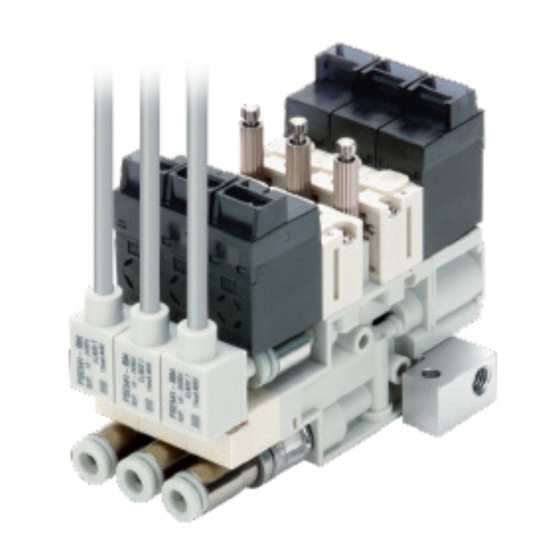
Doc. no. DOC1058584 1. Specifications Refer to the catalog for product specifications. 2. Names of Product Components 2.1 Names of Product Components Single unit Vacuum release flow adjusting needle. Supply pilot valve Lock nut Mounting hole (2 places) Vacuum release valve Air pressure supply (P) port Pressure sensor... -
Page 7: Mounting And Installation
Doc. no. DOC1058584 3. Mounting and Installation 3.1 Mounting 3.1.1 Single unit 1) Directly mount the product on the wall surface, etc. by using the mounting holes (2 xφ2.7) in the side of the body. 2) Use the recommended tightening torque (0.54 to 0.66 Nm) to mount the product. 3.1.2 Manifold product 1) Directly mount the manifold product on the floor surface, etc. -
Page 8: Environment
Doc. no. DOC1058584 3.2 Environment 1) Do not use the product in an atmosphere where corrosive gases, chemicals, sea water, water, or steam is present and may adhere to the product. These may cause failure or malfunction. 2) Do not use the product in an environment where the product could be splashed by oil or chemicals. -
Page 9: Air Supply
Doc. no. DOC1058584 3.3 Air Supply 3.3.1 Air quality 1) Use of compressed air that contains chemical, synthetic oil containing organic solvent, salt, corrosive gas, or the like can cause breakage or malfunction of the product. Do not use compressed air that contains harmful impurities. 2) If the compressed air in use contains a large amount of drainage or carbon powder, it can adhere to the inside of the vacuum generating part (nozzle, diffuser) of the ejector, solenoid valve, or pressure switch for vacuum, and may cause performance degradation or... -
Page 10: Piping
Doc. no. DOC1058584 3.3.2 Air pressure 1) If the product is used with an operating pressure exceeding the maximum operating pressure, the product may be broken. 3.4. Piping 3.4.1 Port sizes The port sizes and operating pressure ranges are listed below. Note that in the manifold specifications, the ports are common ports of the manifold base. - Page 11 Doc. no. DOC1058584 ■ Removal of the tube 1) Press the release button evenly and firmly. 2) Pull out the tubing while keeping the release button pressed. If the release button is not held down with a sufficient force, the tubing cannot be removed. 3) If the removed tubing is to be reused, cut off the used section of the tubing.
-
Page 12: Wiring
Doc. no. DOC1058584 Wiring 1) Do not strongly pull the lead wires for the supply pilot valve, release valve, and pressure sensor, and do not lift the body by pulling the lead wire. The interior of the supply pilot valve, release valve and pressure sensor may be broken, causing the product to malfunction or come off from the connectors. -
Page 13: How To Order
Doc. no. DOC1058584 4. How to Order Refer to the catalog of this product. 5. Dimensions Refer to the catalog of this product. 6.Supply Pilot Valve and Release Valve 6.1 Manual override It is possible to generate vacuum and release vacuum by manual operation. Before performing manual operation, confirm that the safety is ensured even when the product is operated. - Page 14 Doc. no. DOC1058584 6.2 Connecting/Disconnecting the Connector To install the connector, while supporting the solenoid valve, insert the connector straight while holding down the connector lever with your fingers. Ensure that the connector lever clip is properly inserted into the groove of the cover. To remove the connector, hold the solenoid valve and pull out the connector straight pushing the connector lever clip.
- Page 15 Doc. no. DOC1058584 6.4 Initial state When the valve assembly is delivered, the supply valve is on the OFF position, but it may be on the ON position due to the vibration or impact during transportation or device installation. Move supply valve to OFF position manually or energizing before use.
-
Page 16: Pressure Sensor
Doc. no. DOC1058584 7.Pressure Sensor Internal circuit and wiring example PES54□ Voltage output type:1~5V Output impedance Approx. 1 kΩ *For details, refer to the operation manual for PSE54□ Series. 7.2. Precautions 1) If a commercially available switching power supply is used, be sure to install the frame ground (FG) terminal. -
Page 17: Construction And Replacement Parts
Doc. no. DOC1058584 9.Construction and Replacement Parts Refer to the catalog of this product. 10.Maintenance and Checks Implement the maintenance and checks shown below to use the small-size vacuum ejector safely and appropriately for a long period of time. 10.1 How to replace the filter element 1) Use a spanner on the hexagonal surface (width across flats: 7 mm) located on the IN side of the suction filter to remove the suction filter from the product. - Page 18 Doc. no. DOC1058584 10.2 How to replace the supply pilot valve and release valve 1) By loosening the two mounting screws, remove the supply pilot valve or release valve. 2) Replace the supply pilot valve or release valve and assemble it by using the two mounting screws.
- Page 19 Doc. no. DOC1058584 10.4. Precautions 1) Conduct maintenance according to the procedure indicated in the operation manual. If handled improperly, malfunction and damage of machinery or equipment may occur. 2) Compressed air can be dangerous when it is handled incorrectly. Protection of the product as well as element replacement and other maintenance tasks should be performed by a person with good knowledge and experience with pneumatic devices.
-
Page 20: Handling Precautions
Doc. no. DOC1058584 11.Handling Precautions 11.1. Exhaust from the Ejector The exhaust resistance should be as small as possible to obtain the full performance of the vacuum ejector. There should be no shield around the exhaust port for the silencer exhaust specification. Sound absorbing material is gradually clogged in the following cases: - Suction of dust in the environment at the time of adsorption, or - When the air is not clean enough. -
Page 21: Troubleshooting
Doc. no. DOC1058584 12. Troubleshooting If the product fails in any way, perform the following troubleshooting measures. Countermeas Failure phenomenon Possible causes ures Vacuum is not generated Clogging by foreign matter or particles See (1) and (2) Decline in the power supply See (3) and (4) voltage... - Page 22 Doc. no. DOC1058584 ■Countermeasures Countermeasure Oil mist in the supply air or particles in the piping cause clogging if they enter into the ejector. This may cause operation failure. Blow the air piping with air to eliminate particles. As a further supply air cleaning measure, install a mist separator and an air filter.
- Page 23 Doc. no. DOC1058584 Countermeasure When the product suctions a workpiece by generating a vacuum, high speed air coming out of the nozzle collides into the diffuser’s inner diameter and bounces back, generating vibration in the exhaust air. Because of this, the vacuum pressure fluctuates slightly and is not stabilized. The workpiece can be suctioned when the ejector is used in this condition.
- Page 24 Doc. no. DOC1058584 Revision history 4-14-1, Sotokanda, Chiyoda-ku, Tokyo 101-0021 JAPAN Tel: + 81 3 5207 8249 Fax: +81 3 5298 5362 URL https://www.smcworld.com Note: Specifications are subject to change without prior notice and any obligation on the part of the manufacturer. ©...
Need help?
Do you have a question about the ZA Series and is the answer not in the manual?
Questions and answers