
Subscribe to Our Youtube Channel
Related Manuals for SMC Networks THERMO-CON HEC001-W5 Series


Summary of Contents for SMC Networks THERMO-CON HEC001-W5 Series
- Page 1 A_HEC-OM-L008-E サーモコン HEC002-A THERMO-CON Model No. HEC001-W5* HEC003-W5* Keep this manual available at all times.
-
Page 3: Packaged Items
Preface Preface Thank you very much for purchasing SMC Thermo-con (herein referred to as the “product”). This manual describes the operation of the product. Please use this manual for efficient and long use of this unit. Be sure to read this manual efficiently for your deep understanding of overview and safety of this unit before installation or carrying out the relevant operations of this unit. -
Page 4: Table Of Contents
Number of pages Contents 1 SAFETY INSTRUCTIONS --------------------------------------------------------------- 1-1 1.1 B ------------------------------------------------------------------------ 1-1 EFORE USING THE HERMO 1.1.1 S -------------------------------------------------------------------------------------------------------------- 1-1 AFETY TRAINING 1.1.2 I “D ”, “W ”, “C ” “N ” -------------------------------------------------- 1-1 DENTIFICATION OF ANGER ARNING AUTION 1.2 “W ”... - Page 5 Number of pages 3.6.3 L ---------------------------------------------------------------------------------------------- 3-7 EARNING CONTROL FUNCTION 3.6.4 E --------------------------------------------------------------------------------------- 3-7 XTERNAL TUNE CONTROL FUNCTION 3.6.5 T ------------------------------------------------------------------------ 3-7 EMPERATURE SENSOR FINE CONTROL FUNCTION 3.6.6 S ----------------------------------------------------------------------------------------- 3-8 ETTING VALUE MEMORY FUNCTION EEPROM) ------------------------------------------------------------------------------------- 3-8 UNCTION THAT BACKS UP WITH 3.6.7 S ---------------------------------------------------------------------------------------- 3-8 ERIAL...
- Page 6 Number of pages 1) P HEC001 003) ------------------------------------------------------ 5-9 UMP CAPACITY OMMON TO PREPARATION FOR OPERATION --------------------------------------------- 6-1 6.1 P --------------------------------------------------------------------------------------------------------- 6-1 IPING 6.1.1 P -------------------------------------------------------------------------------------- 6-1 REPARATION FOR RADIATING WATER 6.1.2 P --------------------------------------------------------------------------------- 6-2 REPARATION FOR RECIRCULATING FLUID 6.2 W -------------------------------------------------------------------------------------------------------- 6-4 IRING 6.2.1 P...
- Page 7 Number of pages 7.5 S 3 ----------------------------------------------------------------------------------- 7-6 ETTING MODE EVEL 7.5.1 H ------------------------------------------------------------------------------------------------- 7-6 OW TO ENTER AND RETURN 7.5.2 A 3 ------------------------------------------------------------------------------------------------- 7-6 VAILABLE MODE IN EVEL 7.6 D ------------------------------------------------------------------------- 7-7 ETAIL OF SETTING MODE LEVEL 7.6.1 S 1 ---------------------------------------------------------------------------------------------------- 7-7 ETTING MODE EVEL...
- Page 8 Number of pages Figure List Abbreviations Abbreviation (The order of ABC) Meaning Alternating Current Auto Tuning Direct Current EPDM Ethylene Propylene Diene Monomer Error International Electrotechnical Commission Liquid Crystal Display PE (Electricity) Protective Earth PE (Material) Polyethylene Proportional,Integral,Differentiate Polyphenylene Sulfide Process Value Return Received Data...
-
Page 9: Safety Instructions
Safety Instructions Safety Instructions 1.1 Before using the Thermo-con This chapter is dedicated for safety during interaction with the product. The product is operated at high voltage. Therefore, not only those who operate the unit, but those who are in charge of service and who work nearby the product should read carefully and thoroughly understand descriptions related to safety in this manual before starting the work. - Page 10 Safety Instructions Table1-1 Division of DANGER, WARNING, CAUTION, and NOTE DANGER indicates a hazard with a high level of risk which, if not avoided, will result in death or serious injury. DANGER WARNING indicates a hazard with a medium level of risk which, if not avoided, could result in death or serious injury.
-
Page 11: Warning" Label And "Caution" Label
Safety Instructions 1.2 “Warning” label and “Caution” label This product is provided with “Warning” labels and “Caution” labels to inform the operator of hazards related to the product. Check the contents and position of all labels before starting the work. Read all warning and caution labels carefully and keep them in mind. -
Page 12: Precautions For Running
Safety Instructions 1.3 Precautions for running 1.3.1 For safety The product shall be handled only by trained personnel only. Transportation, installation and maintenance including dangerous work shall be done by persons who have full knowledge and experience on the product and the system. Cover panels of the product shall be opened only by qualified service technicians or qualified personnel. -
Page 13: Safety Interlock
Safety Instructions 1.3.2 Safety Interlock This is a function to protect personnel, to restrict operation, that may cause damage to the product or facility, and to remove dangers related to safety. This unit has several interlock functions, which activate when dangerous operation or condition occurs to stop operation and make it safe. - Page 14 Safety Instructions Table1-3 Safety interlock list (Part 1) Description Part Cause Overheat in Heat Thermostat Detects abnormal heat in heat exchanger. Exchanger Switching power supply Detects abnormal current, voltage, Internal circuit failure temperature or fan failure. Low recirculating fluid Detects low level of recirculating fluid in the 3(Note) Level sensor level...
-
Page 15: Caution On Installation
Caution on Installation Caution on Installation Pay special attention to the safety of all personnel when installing and transporting the product. The product is heavy, be careful when installing or moving the product. Only trained personnel can perform work such as installation, transportation and maintenance of the product. -
Page 16: Installation
Caution on Installation 2.2 Installation • Fluid leakage from the thermo-con can affect peripheral equipment. Install a drain pan at the bottom of the place where the thermo-con is installed to catch the fluid leakage and prevent this problem. Also, provide a way of detecting fluid leakage, such as a leak sensor, with the drain pan so that an alarm will be generated in the case of leakage. -
Page 17: Mounting
Caution on Installation 2.3 Mounting The product should be mounted as follows. A fixing foot is prepared for the Thermo-con (accessory). Mount it on the Thermo-con body before use. Remove the 2pcs of screws on the front and back of the Thermo-con respectively, and mount the attached foot. -
Page 18: Piping
Caution on Installation 2.4 Piping Ensure the flow rate of the recirculating fluid is as high as possible to maintain the temperature stability. Therefore, the length of the external piping should be minimized and internal diameter should be as large as possible. Piping must have sufficient strength for the maximum discharge pressure of the recirculating circuit. -
Page 19: Preparation For Operation
Preparation for Operation Unit overview 3.1 Method of displaying model H E C 00* - W 5 * - *** Nil : No option With flow switch NPT fitting With level switch * They can be combined, but must be in the order F, N, L. Cooling capacity A : RS-485 001 : 140W... -
Page 20: Model No. Label
Preparation for Operation 3.3 Model No. label A model No. label is attached to the unit in the position shown below. Model No. label Fig.3-1 Position of Model No. label Fig.3-2 Legend of Model No. label... -
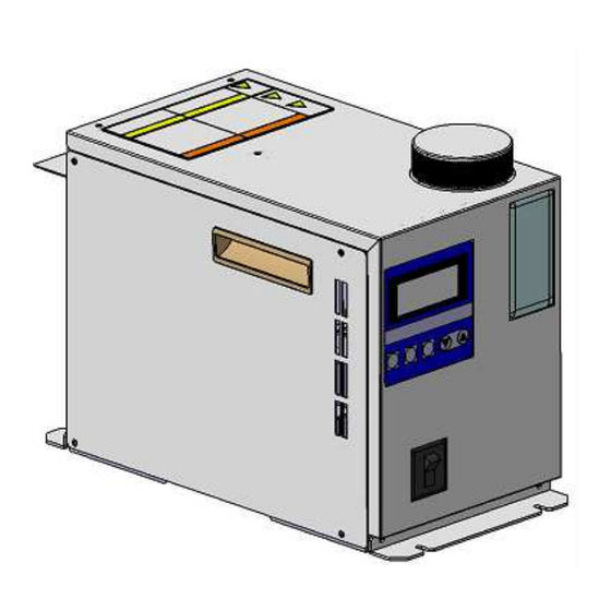
Page 21: Appearance
Preparation for Operation 3.4 Appearance Fig.3-3 Outside drawings of HEC... -
Page 22: Operating Principles
Preparation for Operation 3.5 Operating Principles The operating principle of the product is explained below 3.5.1 Construction and Principle of Thermoelectric Module The product controls the temperature of the recirculating fluid using thermoelectric modules (Peltier Modules). A thermoelectric module (electronic cooling and heating element) is a device consisting of multiple semiconductor elements. -
Page 23: Construction Of Temperature Controlling Device
Preparation for Operation 3.5.2 Construction of temperature controlling device Several thermoelectric modules are installed in a heat exchanger. Radiating water flows on one side of the thermoelectric module, and recirculating fluid flows on the other side of the thermoelectric module. DC output transmitted from a switching power supply is connected to the thermoelectric module, and a controller controls the DC output from the switching power supply. -
Page 24: Electrical Diagram
Preparation for Operation 3.5.3 Electrical diagram Fig.3-6 Electrical diagram... -
Page 25: Functions
Preparation for Operation 3.6 Functions 3.6.1 Auto tuning This function sets the values necessary for the control system such as PID (proportional band, integral time, derivative time and ratio of cooling/ heating gain) automatically. *Depending on piping and other conditions, sometimes auto tuning cannot be controlled properly even if it is finished correctly. -
Page 26: Setting Value Memory Function
Preparation for Operation Internal sensor value for alarm includes the fine control value. Internal sensor value for alarm = Internal sensor value – Fine control value 3.6.6 Setting value memory function (Function that backs up with EEPROM) This function backs up all the manually set values to nonvolatile memory (EEPROM). Even if the power is turned off the set values are saved and will be restored at power on. -
Page 27: Names And Functions Of Components
Preparation for Operation Names and Functions of Components 4.1 Description of Parts External sensor Radiating water connector Alarm output connector Recirculating fluid Communication connector Power supply connector Radiating water Recirculating fluid Drip proof cover Drain Reservoir Cap Level Gauge Handle Operation panel and Display Power Switch Fig.4-1 Components of HEC... -
Page 28: Operation Panel
Preparation for Operation Table 4-1 Function of Components Description Function Operation panel and display Various displays are shown and settings are input. Power Switch (circuit protector) Turns the power supply of the product on and off. Level gauge It displays liquid level of the internal tank. Reseirvor cap This is a screwed type cap. -
Page 29: Display
Preparation for Operation 4.3 Display 1st line 2nd, 3rd line Indicates No. Current corresponding to the alarm temp.[PV]]and target which arises and [WRN] temp.[SV] during ERR1 1 WRN comes to light up when normal operation. P V < 3 1 . 6 °... -
Page 31: Operation
Operation Specifications 5.1 Specifications of HEC001 Table5-1 Specifications of HEC001 Type HEC001-W5A HEC001-W5B Communication RS-485 RS-232C Set temp. rannge °C 10.0 to 60.0 Measured temp. range °C -9.9 to 99.9 Temp. °C Humidity No dew condensation : 10 to 35 : 35 to 85%RH( Ambient environment Temp. -
Page 32: Specifications Of Hec003
Operation 5.2 Specifications of HEC003 Table5-2 Specifications of HEC003 Type HEC003-W5A HEC003-W5B Communication RS-485 RS-232C Set temp. rannge 10.0 to 60.0 °C Measured temp. range -9.9 to 99.9 °C Temp. °C Humidity No dew condensation Ambient environment : 10 to 35 : 35 to 85%RH( Temp. -
Page 33: Performance Chart
Operation 5.3 Performance chart Values on performance chart are not guaranteed values but representative values. The values used for consideration should not be at the very limit for the safety. 5.3.1 Performance of HEC001 1) Cooling capacity Recirculating fluid flowrate : 5L/min Ambient ... -
Page 34: Heating Capacity
Operation 2) Heating capacity Recirculating fluid flowrate : 5L/min Ambient Temp. : 20 ℃ Fluid : water Radiating water Temp. °C Recirculating fluid temp. ℃ Fig. 5-3 Heating capacity *The Radiating water flow rate of 1L/min is for reference. Radiating water Temp. -
Page 35: Pressure Loss Of Radiating Water
Operation 3) Pressure loss of radiating water Fluid : water 0.02 0.015 0.01 0.005 Frow rate L/min Fig. 5-5 Pressure loss... -
Page 36: Performance Of Hec003
Operation 5.3.2 Performance of HEC003 1) Cooling capacity Recirculating fluid flowrate : 5L/min Ambient Temp. : 20 ℃ Fluid : water 1000 Radiating water Temp. °C Recirculating fluid temp. ℃ Fig. 5-6 Cooling capacity *The Radiating water flow rate of 1L/min is for reference. Radiating water Temp. -
Page 37: Heating Capacity
Operation 2) Heating capacity Recirculating fluid flowrate : 5L/min Ambient Temp. : 20 ℃ Fluid : water 1000 Radiating water Temp. °C Recirculating fluid temp. ℃ Fig. 5-8 Heating capacity *The Radiating water flow rate of 1L/min is for reference. Radiating water Temp. -
Page 38: Pressure Loss Of Radiating Water
Operation 3) Pressure loss of radiating water Fluid : water 0.03 0.025 0.02 0.015 0.01 0.005 Frow rate L/min Fig. 5-10 Pressure loss... -
Page 39: Performance Of Pump Capacity
Operation 5.3.3 Performance of Pump capacity 1) Pump capacity(Common to HEC001 and 003) The pressure on Y axis stands for discharge pressure of recirculating fluid from Thermo-con. Fluid : water 0.12 0.10 0.08 0.06 0.04 0.02 0.00 Frow rate L/min Fig. -
Page 41: Preparation For Operation
Operation Preparation for Operation 6.1 Piping 6.1.1 Preparation for radiating water The piping for radiating water is connected as below. 1) Connect fittings to the ports marked [RADIATING WATER IN] and [RADIATING WATER OUT] at the rear side of the equipment. (the same fittings should be used for IN and OUT) [Port size ---3/8] 2) When connecting a fitting to the port, hold the port a wrench to... -
Page 42: Preparation For Recirculating Fluid
Operation 6.1.2 Preparation for recirculating fluid The piping for recirculating fluid is connected as below. 1) Connect fittings to the ports marked [RECIRCULATING FLUID IN] and [RECIRCULATING FLUID OUT] and [DRAIN] at the rear side of the equipment. (the same fittings should be used for IN and OUT) (1) [Port size Rc 3/8] (2) [Drain Rc1/4] 2) A plug is mounted on DRAIN port for recirculating fluid. - Page 43 Operation The maximum operating pressure of the recirculating fluid is 0.1MPa. If pressure goes over this limit, water may leak from the tank and piping inside the thermo-con. An operation at higher ambient temperature or temperature up/down (heating/cooling) cycle shall be avoided. The lifetime of the pump and Thermo-electric modules is shortened.
-
Page 44: Wiring
Operation 6.2 Wiring 6.2.1 Power supply The power supply shall be connected with supplied power supply cable. Before wiring confirm the power supply at factory has enough capacity and the voltage is within specified value (with reference to electrical specifications of the power supply). This product is provided with a power supply cable. -
Page 45: Check・Repair
Operation 6.3 Check・Repair The following checks shall be performed before operation. 6.3.1 Daily check Indication of display panel: Check temperature condition and confirm whether or not the alarm occurs. Check the recirculating fluid is not contaminated. Once the fluid is contaminated, it may degrade the performance or shorten the life time. -
Page 46: Repair And Maintenance
Operation 6.3.3 Repair and maintenance The repair and maintenance services of this unit are performed only at our factory. The service requiring a trip regardless of inside and outside of Japan is not provided. When returning the product for repair or maintenance service, discharge all the fluid inside the Thermo-con in order to avoid fluid leakage during transportation, and seal it. -
Page 47: Operation
Operation Operation This chapter describes the detailed information on how to operate. 7.1 Start of operation 7.1.1 Confirmation before operation 1) Confirm that the recirculating fluid has reached a L level 2) Supply radiating water. SOFT VERSION 3) Confirm that there is no incorrect wiring of the 1 . -
Page 48: How To Operate
Operation 7.2 How to operate 1. The different 3 levels are available depending on the content, Operation which needs to be set. Level 1 : Used normally and setting of target temp. and offset are included. (Refer to 7.3.) Operation Level 2 : Used at maintenance and initial setting. -
Page 49: Setting Mode , Level
Operation 7.3 Setting Mode, Level 1 The method to enter to and return from setting mode Level 1 and which mode can be set in the level are explained below. 7.3.1 How to enter and return Press [SEL] key while power is turned on. Then, the indication on [MODE] is changed depending on the number of press and the data in the indicated mode can be set. - Page 50 Operation Table7-1 Available mode in Level 1 Setting range Modes Setting contents Default (Min. increment) 10.0 to 60.0 °C Target Temp. (0.1 °C) Sets target temp. for control. 25.0 (No indication on display) [Standard specification] Selects control operation mode from those shown below.
- Page 51 Operation 7.4 Setting mode, Level 2 The method to enter to and return from setting mode Level 2 and which mode can be set in the level are explained below. 7.4.1 How to enter and return Press [SEL] and [ ] keys at the same time while power is turned on. Then, the indication on [MODE] is changed depending on the number of press and the data in the indicated mode can be set.
- Page 52 Operation 7.5 Setting mode, Level 3 The method to enter to and return from setting mode Level 3 and which mode can be set in the level are explained below. 7.5.1 How to enter and return Press [SEL] and [ ] keys at the same time while power is turned on. Then, the indication on [MODE] is changed depending on the number of press and the data in the indicated mode can be set.
-
Page 53: Detail Of Setting Mode Level
Operation 7.6 Detail of setting mode level The each setting mode level is explained below in detail. 7.6.1 Setting mode, Level 1 1. Indication of current temperature [PV] < 2 3 . 0 ° C # 1 Indication range: -9.9 to 99.9 °C 2 5 . - Page 54 Operation 4. External sensor sampling cycle setting mode Setting range: 10 to 999sec E x t e r n a l S e n s o r Min. increment: 1sec S a m p l i n g C y c l e Indicated content: External sensor sampling cycle M O D E <...
-
Page 55: Setting Mode, Level
Operation 9. Low Temp. Cutoff L o w T e m p . C u t o f f Setting range : 0.0 to 59.0 °C Min. increment : 0.1 °C M O D E < 0 . 0 ° C Indicated content : Low temp. - Page 56 Operation 6. D Constant Setting range : 0.0 to 99.9sec D C o n s t a n t Min. increment : 0.1sec Indicated content : D constant(Ex. : 0.0sec) M O D E < 0 . 0 s e c Function : Sets differential time used for PID control.
-
Page 57: Setting Mode, Level
Operation 7.6.3 Setting mode, Level 3 1.Unit Number Setting range : 0 to F (Hex decimal) Indicated content : Unit number (Ex. : 0) U n i t N u m b e r Function : Sets unit number used. This item is applicable only when multiple units are used. -
Page 59: Alarm
Alarm Alarm This chapter explains the various alarms that the product has. 8.1 How to Identify Alarm The alarm is identified as shown on the following table. Table8-1 Alarm information Condition After Alarm Occurrence After indication of the software version, the error No. [ERR**] starts blinking and then a description of the error is displayed, and [MODE], “Shut Off”... -
Page 60: Alarm Indication
Alarm 8.2 Alarm indication Blink E R R 1 4 T h e r m o s t a t A l a r m M O D E < S h u t o f f Fig.8-1 Alarm indication in the event ERR14 arises Blink E R R 1 4 P B R a n g e... -
Page 61: How To Reset Alarm
Alarm 8.3 How to reset alarm The alarm can be reset in the following manner. Table8-2 Reset of alarm Alarm code Description Manner of reset Restart the power supply. ERR00 CPU hung-up In this case if the alarm can’t be reset, repair is ERR01 CPU check failure required. - Page 62 Alarm Table8-3-2 Alarm code list (Part2) Code Description Contents Condition: Switching power supply has a problem (The fan stops and temperature is excessively high.) or Thermo-module is short- DC power circuited. ERR11 supply failure After alarm occurrence: The product (temp. control, pump) stops. Indication: [DC Power Voltage Failure] Condition: Fluid temp.
-
Page 63: Troubleshooting
Alarm 8.5 Troubleshooting Troubleshooting methods when the alarm appears is explained as follows. Table8-4-1 Troubleshooting (Part1) Code Reason for alarm setting Cause (1) Move the product to an environment with little (1) High level noise on the power line, noise, turn ON the power supply. If there is no ERR00 ground line or temp. - Page 64 Alarm Table8-4-2 Troubleshooting (Part2) Code Reason for alarm setting Cause (1) Decrease radiating water temp. and increase a flow rate. (1) Radiating water temp is high or flow rate is not enough. (2)(3) If flow rate of recirculating fluid is zero, the ERR14 temperature of recirculating fluid can’t be measured (2) Flow rate is zero.
-
Page 65: Appendix
Appendix Appendix This chapter includes information about the connections for the product and a method for calculating the dew point. 9.1 Signal and style of connectors The type and signals used of each connector that are on the product are shown in the table below. Table9-1 Signals and Type of Connectors Description Signal... - Page 66 Appendix Table9-2 Signal and style of connectors Description Signal Style and part No. Output Cutoff Alarm a contact (OPEN During Alarm) Output Cutoff Alarm Common Output Cutoff Alarm b contact (CLOSE During Alarm) Unused Alarm Output connector Temperature Alarm a contact (OPEN During Alarm) D-Sub 9pin (Pin) Temperature Alarm Common...
-
Page 67: Power Supply Cable
Appendix 9.2 Power Supply Cable Table 9-3 Power Supply Cable Description Specifications Connector IEC60320 C13 Rating Voltage: 250V (VDE) (UL) Rating Current: 10A (VDE) 15A (UL) Cable Rating Voltage: VDE 300/500V UL • CSA 600V AWG14-3 Color: Black AC100 to 240V Green/Yellow Power supply cable 2000mm (attachment) Do not use the included power supply cable for any purposes other than... -
Page 68: Calculation Of Dew Point (From Psychrometric Chart)
Appendix 9.3 Calculation of dew point (from psychrometric chart) Fig.9-1 Moisture air diagram 1) Measure the ambient temperature and relative humidity. 2) Plot the ambient temperature on the horizontal axis (Ex. 24 °C), and then draw a perpendicular line. 3) Find the intersection (A) of the curve, which is equal to relative humidity (Ex. 50%). 4) Draw a line from point (A) parallel to horizontal axis, and find the intersection (B) of the curve for 100% relative humidity. -
Page 69: Applicable Standard/Regulation
Appendix 9.4 Applicable standard/regulation 9.4.1 Overseas standard The Thermo-con complies with the following standard. 2004/108/EC Low Voltage Directive 2006/95/EC UL<MET> : UL61010-1 SEMI : S2-0706, F47-0200 9.4.2 When the product is exported, strictly follow the laws required by the Ministry of Economy, Trade and Industry (Foreign Exchange and Foreign Trade Control Law). - Page 71 Revision history Rev.E: May, 2024 Tel: + 81 3 5207 8249 Fax: +81 3 5298 5362 https://www.smcworld.com Note: Specifications are subject to change without prior notice and any obligation on the part of the manufacturer. © SMC Corporation All Rights Reserved...
- Page 73 Revision history Rev.E: May, 2024 https://www.smcworld.com Note: Specifications are subject to change without prior notice and any obligation on the part of the manufacturer. © SMC Corporation All Rights Reserved...
Need help?
Do you have a question about the THERMO-CON HEC001-W5 Series and is the answer not in the manual?
Questions and answers