Table of Contents
Advertisement
Quick Links
Installation, Operation, and Maintenance
CDHF and CDHG Water-Cooled Cen-
TraVac™ Chillers
With Tracer® AdaptiView™ Control
Models:
CDHF, CDHG
Only qualified personnel should install and service the equipment. The installation, starting up, and servicing of
heating, ventilating, and air-conditioning equipment can be hazardous and requires specific knowledge and training.
Improperly installed, adjusted or altered equipment by an unqualified person could result in death or serious injury.
When working on the equipment, observe all precautions in the literature and on the tags, stickers, and labels that are
attached to the equipment.
March 2020
SAFETY WARNING
CDHF-SVX01N-EN
X39641076130
Advertisement
Table of Contents

Related Manuals for Trane CenTraVac CDHF Series


Summary of Contents for Trane CenTraVac CDHF Series
- Page 1 Installation, Operation, and Maintenance CDHF and CDHG Water-Cooled Cen- TraVac™ Chillers With Tracer® AdaptiView™ Control Models: CDHF, CDHG X39641076130 SAFETY WARNING Only qualified personnel should install and service the equipment. The installation, starting up, and servicing of heating, ventilating, and air-conditioning equipment can be hazardous and requires specific knowledge and training. Improperly installed, adjusted or altered equipment by an unqualified person could result in death or serious injury.
- Page 2 A A L L W W A A Y Y S S r r e e f f e e r r t t o o a a p p p p r r o o p p r r i i a a t t e e S S a a f f e e t t y y D D a a t t a a impact to the environment. Trane advocates the...
- Page 3 N N O O T T m m i i x x r r e e f f r r i i g g e e r r a a n n t t s s o o r r o o i i l l s s ! ! • Start-up must be performed by Trane or an agent of Trane specifically authorized to perform startup and This Installation, Operation, and Maintenance manual warranty of Trane®...
- Page 4 To learn about available training opportunities contact Trane This document and the information in it are the University™. property of Trane, and may not be used or reproduced Online: www.trane.com/traneuniversity in whole or in part without written permission. Trane...
-
Page 5: Table Of Contents
Table of Contents Unit Nameplate......8 Waterbox Locations ..... 29 Grooved Pipe Coupling . - Page 6 Operating Principles ..... . . 67 Trane-supplied Starter Wiring ... . 53 General Requirements .
- Page 7 Installation Completion and Request for Trane Service......96 Leak Testing ......89...
-
Page 8: Unit Nameplate
Unit Nameplate The unit nameplate is located on the left side of the left Figure 1. Typical unit nameplate hand control panel. A typical unit nameplate is illustrated in the following figure and contains the following information: • Unit model and size descriptor •... -
Page 9: Model Number Descriptions
Model Number Descriptions Digit 1, 2, 3 — Unit Function Digit 35 — Starter Type Right-Hand Digit 4 — Development Sequence Digit 36 — Enhanced Protection Digit 5, 6, 7, 8 — Nominal Tonnage Digit 37 — Generic BAS Digit 9 — Unit Voltage Digit 38 —... -
Page 10: Pre-Installation
4. Check the oil sump sight glasses to verify that the outside of every entrance. sump was factory-charged with 9 gallons (34.1 L) of oil. If no oil level is visible, contact your local Trane • The equipment room should be properly vented to sales office. - Page 11 Meet foundation requirements • Safety chains Rigging • Rigging shackles • Lifting beam • Trane will perform or have direct on-site supervision Disassembly/Reassembly of the disassembly and (as required) reassembly work (contact your local Trane office for pricing) • Isolation pads or spring isolators •...
-
Page 12: Storage Requirements
Start-up must be performed by Trane or an agent of Trane specifically authorized to perform start-up and warranty of Trane® products. Contractor shall provide Trane (or an agent of Trane specifically authorized to perform start-up) with notice of the scheduled start-up at least two weeks prior to the scheduled start-up. - Page 13 If the chiller will be stored for more than six months after production, contact your local Trane Service Agency for required extended storage actions to minimize impact to the chiller and preserve the warranty.
-
Page 14: Unit Components
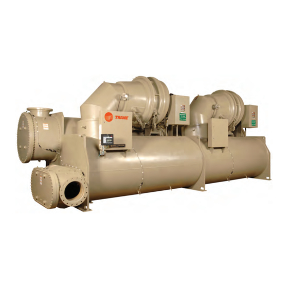
P P r r e e - - I I n n s s t t a a l l l l a a t t i i o o n n Unit Components Figure 3. Typical Duplex™ CenTraVac™ chiller N N o o t t e e : : The control panel side of the unit is always designated as the front side of the unit. -
Page 15: Unit Clearances And Weights
Unit Clearances and Weights Recommended Unit Clearances • Use a housekeeping pad to provide better service clearances; refer to submittal for more information. Adequate clearances around and above the chiller are Per National Electric Code (NEC) Article 110: Unit required to allow sufficient access for service and mounted starters from 0 to 600V require a 42 inch maintenance operations. -
Page 16: General Weights
For specific weights for your should be used for general information chiller, refer to your submittal package. only. Trane does not recommend using this weight information for considerations Table 2. Representative weights, 60 Hz chillers (lb) Comp Size... - Page 17 U U n n i i t t C C l l e e a a r r a a n n c c e e s s a a n n d d W W e e i i g g h h t t s s Table 4.
-
Page 18: Installation: Mechanical
INDOOR USE ONLY and as such has I I m m p p o o r r t t a a n n t t : : Trane will not assume responsibility for NEMA Type 1 enclosures. equipment problems resulting from an •... - Page 19 I I n n s s t t a a l l l l a a t t i i o o n n : : M M e e c c h h a a n n i i c c a a l l mm) diameter lifting hole is provided at each of the chiller feet (refer to “Unit Isolation,”...
-
Page 20: Special Lift Requirements
. . it from the unit. Contact Trane or an agent of T T o o p p r r e e v v e e n n t t o o i i l l m m i i g g r r a a t t i i o o n n o o u u t t o o f f t t h h e e o o i i l l t t a a n n k k d d u u r r i i n n g g... -
Page 21: Isolation Pads
Trane sales office for further information. front I I m m p p o o r r t t a a n n t t : : When determining placement of isolation pads or spring isolators, remember that the... -
Page 22: Leveling The Unit
I I n n s s t t a a l l l l a a t t i i o o n n : : M M e e c c h h a a n n i i c c a a l l I I m m p p o o r r t t a a n n t t : : Do NOT allow the screws to protrude Figure 8. - Page 23 I I m m p p o o r r t t a a n n t t : : Immediately report any unit damage method to level the unit. incurred during handling or installation at the job site to the Trane sales office. CDHF-SVX01N-EN...
-
Page 24: Installation: Water Piping
. . I I m m p p o o r r t t a a n n t t : : Trane strongly recommends using the... -
Page 25: Strainers
I I n n s s t t a a l l l l a a t t i i o o n n : : W W a a t t e e r r P P i i p p i i n n g g Strainers Paddle switch installation: 1. - Page 26 . . Trane application. It is NOT necessary to 2.
-
Page 27: Evaporator And Condenser Water
I I n n s s t t a a l l l l a a t t i i o o n n : : W W a a t t e e r r P P i i p p i i n n g g Figure 12. -
Page 28: Water Piping Connections
Expenses that result from a failure to EVSZ 1-Pass 2-Pass 3-Pass follow this recommendation will NOT be paid by Trane. Waterboxes with multiple pass arrangements utilize a 323.9 273.0 219.1 baffle to separate the passes. These baffles are designed for a maximum pressure of 20 psid 406.4... -
Page 29: Waterbox Locations
(Condenser 032– provided No adapter CDHF and 050 150 psig Victaulic® required CDHG [1034.2 kPaG] coupling non-marine only) Customer Trane provided provided Victaulic® (all CDHF and Victaulic®-to- others) Victaulic® CDHG flange adapter coupling Figure 16. Customer piping connection types Flanged Victaulic®... -
Page 30: Victaulic Gasket Installation
I I n n s s t t a a l l l l a a t t i i o o n n : : W W a a t t e e r r P P i i p p i i n n g g Victaulic Gasket Installation Figure 17. -
Page 31: Screw-Tightening Sequence For Water
I I n n s s t t a a l l l l a a t t i i o o n n : : W W a a t t e e r r P P i i p p i i n n g g Table 10. -
Page 32: 16 Screws
(1034.2 kPaG) or 300 psig (2068.4 kPaG); refer to unit nameplate or to submittal documentation. Eddy Current Testing Trane recommends conducting an eddy current inspection of the condenser and evaporator tubes in water-cooled chillers every three years. Eddy current tests are intended to identify defects on or within the walls of heat exchanger tubing that could lead to in- service tube failures. - Page 33 I I n n s s t t a a l l l l a a t t i i o o n n : : W W a a t t e e r r P P i i p p i i n n g g maintenance by providing information about eddy current technology and heat exchanger tubing.
-
Page 34: Vent Piping
Capacities of various vent line sizes and lengths. codes do. However, this data applies only to conventional Testing conducted in Trane laboratories has qualified pressure-relief valves and NOT to balanced relief the following materials for PVC pipe construction as valves, rupture members (as used on Trane®... -
Page 35: Vent Line Installation
V V e e n n t t P P i i p p i i n n g g N N o o t t e e : : To determine the total C C value for a specific facing the chiller side as shown in the following unit, add the appropriate C C values for the figure (rupture disk location and cross section). - Page 36 For chillers with R-123 refrigerant, refer to Installation, Operation, and Maintenance: R-123 Low-Pressure Refrigerant Handling Guidelines Conservation and Safe Handling of R-123 Refrigerant in Trane Chillers for Service Technicians (CTV-SVX05*-EN). For CDHF-SVX01N-EN...
- Page 37 9 in. (228.6 mm) failure to properly install RuptureGuard™ of valve discharge. Refer to ASHRAE will NOT be paid by Trane. Standard 15 for additional requirements on piping rupture disk and relief valve vent lines.
-
Page 38: Vent Line Sizing Reference
V V e e n n t t P P i i p p i i n n g g Vent Line Sizing Reference Table 12. “C” value used to determine rupture disk vent line sizes; for use with the following figure Evaporator Size (EVSZ) Condenser Size (CDSZ) Total “C”... - Page 39 V V e e n n t t P P i i p p i i n n g g Figure 27. Rupture disk vent pipe sizing; for use with the preceding table Pipe size as a Function of “C” Value and Length of Run 1000 Pipe Size (I.D.) Friction Factor...
- Page 40 V V e e n n t t P P i i p p i i n n g g ASHRAE Standard 15 • d = inside diameter of pipe or tube, in. (mm) • ln = natural logarithm 0.214d –...
-
Page 41: Insulation
. . • 75 percent relative humidity Operation outside of normal design conditions as defined in this section may require additional insulation; contact Trane for further review. Table 13. Evaporator insulation requirements Free Cooling Standard Unit 3/4 in. (19.05 mm) 3/8 in. - Page 42 I I n n s s u u l l a a t t i i o o n n Figure 28. Recommended area for unit insulation Line to eductor Line from evaporator Filter drier and eductor lines Suction cover Suction elbow Suction...
-
Page 43: Installation: Controls
Installation: Controls This section covers information pertaining to the UC800 controller hardware. For information about the Tracer® AdaptiView™ display, which is used to interface with the internal chiller data and functions provided by the UC800, refer to Tracer AdaptiView Display for Water-cooled CenTraVac Chillers Operations Guide (CTV-SVU01*-EN). -
Page 44: Communication Interfaces
I I n n s s t t a a l l l l a a t t i i o o n n : : C C o o n n t t r r o o l l s s Figure 29. - Page 45 I I n n s s t t a a l l l l a a t t i i o o n n : : C C o o n n t t r r o o l l s s Figure 30.
- Page 46 I I n n s s t t a a l l l l a a t t i i o o n n : : C C o o n n t t r r o o l l s s Figure 31.
- Page 47 I I n n s s t t a a l l l l a a t t i i o o n n : : C C o o n n t t r r o o l l s s Figure 32.
- Page 48 I I n n s s t t a a l l l l a a t t i i o o n n : : C C o o n n t t r r o o l l s s Figure 33.
- Page 49 I I n n s s t t a a l l l l a a t t i i o o n n : : C C o o n n t t r r o o l l s s Figure 34.
-
Page 50: Installing The Tracer Adaptiview
The display must be installed at the site. Figure 35. Tracer AdaptiView shipping location I I m m p p o o r r t t a a n n t t : : For best results, Trane, or an agent of Trane, must install the Tracer®... -
Page 51: Arm
I I n n s s t t a a l l l l a a t t i i o o n n : : C C o o n n t t r r o o l l s s Figure 37. -
Page 52: Electrical Requirements
Electrical Requirements Installation Requirements provide electrical access, exercise care to prevent debris from falling inside the enclosure. Refer to W W A A R R N N I I N N G G installation information shipped with the starter or submittal drawings. -
Page 53: Trane-Supplied Starter Wiring
Wires, lugs, and fuses/breakers are sized based on National Electric Code NEC [NFPA 70] and UL 1995. 1Q1 Circuit Breaker to Starter connects to 2X16 Starter Panel Terminal for all starter types except the AFDG (Trane-supplied remote Danfoss AFD); for the AFDG, 1Q1 Circuit Breaker to Starter connects to 2X13 Starter Panel Terminal. -
Page 54: Wiring
All wiring to be in accordance with National Electrical Code (NEC) and any local codes. Starter by Others Specification available from your local Trane sales office. Wires, lugs, and fuses/breakers are sized based on National Electric Code (NEC) [NFPA 70] and UL 1995. - Page 55 C C u u s s t t o o m m e e r r - - s s u u p p p p l l i i e e d d R R e e m m o o t t e e S S t t a a r r t t e e r r W W i i r r i i n n g g Table 17.
-
Page 56: Power Supply Wiring
Power Supply Wiring W W A A R R N N I I N N G G stamped on the chiller nameplate and transformer load on L1 and L2. P P r r o o p p e e r r F F i i e e l l d d W W i i r r i i n n g g a a n n d d G G r r o o u u n n d d i i n n g g •... -
Page 57: Power Factor Correction Capacitors
P P o o w w e e r r S S u u p p p p l l y y W W i i r r i i n n g g Power Factor Correction W W A A R R N N I I N N G G Capacitors (Optional) H H a a z z a a r r d d o o u u s s V V o o l l t t a a g g e e w w / / C C a a p p a a c c i i t t o o r r s s ! ! F F a a i i l l u u r r e e t t o o d d i i s s c c o o n n n n e e c c t t p p o o w w e e r r a a n n d d d d i i s s c c h h a a r r g g e e... -
Page 58: Interconnecting Wiring
P P o o w w e e r r S S u u p p p p l l y y W W i i r r i i n n g g in the preceding figure (Option 2). This ensures that the Figure 43. -
Page 59: Wire Terminal Lugs
. . Bus bars and extra nuts are available as a Trane option. -
Page 60: Starter To Control Panel Wiring
• Separate low-voltage (less than 30V; refer to the The unit submittal includes the field wiring connection tables in “Trane-supplied Starter Wiring,” p. 53 diagram and the starter-to-control-panel connection “Customer-supplied Remote Starter Wiring,” p. diagram (showing the electrical connections required... -
Page 61: 10 To 13.8Kv Medium Voltage Motor
D-rings if removal is needed for clearance purposes. N N o o t t e e : : Trane assumes no responsibility for the design, documentation, construction, compatibility, N N o o t t e e : : If the box is removed for installation... -
Page 62: Motor Supply Wiring
Before beginning wiring and torquing, ensure proper trays. To limit the effects of corona or ionization with motor terminal care and do NOT apply any excess cables carrying more than 2000V, Trane requires that stress. the power cable have a metallic shield, unless the cable is specifically listed or approved for non-shielded use. -
Page 63: System Control Circuit Wiring
System Control Circuit Wiring (Field Wiring) Table 20. Unit control panel wiring 120 Vac Standard Control Circuits: Unit Control Panel Control Wiring Input or Output Type Unit Control Terminations Contacts (120 Vac) Chilled Water Flow Proving Input Binary Input Normally Open, Closure with Flow 1X1-5 to 1A6-J3-2 Condenser Water Flow Proving Binary Input... -
Page 64: Water Pump Interlock Circuits And Flow
S S y y s s t t e e m m C C o o n n t t r r o o l l C C i i r r c c u u i i t t W W i i r r i i n n g g ( ( F F i i e e l l d d W W i i r r i i n n g g ) ) Table 20. -
Page 65: Condenser Water Pump
The sensor will be configured (given its identity and sequence will be allowed to proceed and a loss of become functional) at start-up when the Trane service condenser water flow during chiller operation will technician performs the start-up configuration. It will result in a chiller shut-down. -
Page 66: Starter Module Configuration
Please refer to the submittals and drawings that source control power (115 Vac) be utilized to shipped with the unit. Additional wiring drawings for power up the control circuits. This needs to be CenTraVac™ chillers are available from your local done in each panel. Trane office. CDHF-SVX01N-EN... -
Page 67: Operating Principles
CenTraVac™ chiller. If mechanical problems Figure 46. Pressure enthalpy curve, 3-stage do occur, however, contact a Trane service technician to ensure proper diagnosis and repair of the unit. I I m m p p o o r r t t a a n n t t : : Although CenTraVac™ chillers can operate... -
Page 68: Duplex Compressor Sequencing
O O p p e e r r a a t t i i n n g g P P r r i i n n c c i i p p l l e e s s condense. The liquid refrigerant then flows out of the start and stop both compressors to minimize startup bottom of the condenser, passing through an orifice pull down time. -
Page 69: Compressor 1
O O p p e e r r a a t t i i n n g g P P r r i i n n c c i i p p l l e e s s Fixed Sequence—Compressor 2 / chiller capacity exceeds the stage-on load point for 30 seconds. -
Page 70: Simultaneous Compressor Start
O O p p e e r r a a t t i i n n g g P P r r i i n n c c i i p p l l e e s s Figure 53. Duplex™ chiller sequence of operation: Figure 54. -
Page 71: Oil And Refrigerant Pump
O O p p e e r r a a t t i i n n g g P P r r i i n n c c i i p p l l e e s s the number of free starts is programmed to “1”, and and the also display the time remaining in the restart the Start to Start Time Setting is programmed to inhibit. - Page 72 O O p p e e r r a a t t i i n n g g P P r r i i n n c c i i p p l l e e s s Figure 55. Oil refrigerant pump, evaporator sizes EXCEPT 032 short/long Compressor lubrication system Motor cooling system Oil reclaim system...
-
Page 73: Motor Cooling System
O O p p e e r r a a t t i i n n g g P P r r i i n n c c i i p p l l e e s s C C A A U U T T I I O O N N by a qualified technician as necessary for oil return. -
Page 74: Start-Up And Shut-Down
Start-up and Shut-down This section provides basic information on chiller • The first line of text in the circles is the visible top operation for common events. level operating modes that can be displayed in Tracer® AdaptiView™. Sequence of Operation •... -
Page 75: Start-Up Sequence Of Operation
S S t t a a r r t t - - u u p p a a n n d d S S h h u u t t - - d d o o w w n n Figure 57. Sequence of operation: Tracer AdaptiView power up Loading UI Black Screen Grey Screen (User Interface from UC800) Display Ready First Trane Logo Second Trane Logo 12 seconds 18 seconds 30 seconds 15 seconds 15 seconds... - Page 76 S S t t a a r r t t - - u u p p a a n n d d S S h h u u t t - - d d o o w w n n Figure 58.
- Page 77 S S t t a a r r t t - - u u p p a a n n d d S S h h u u t t - - d d o o w w n n Figure 59.
- Page 78 S S t t a a r r t t - - u u p p a a n n d d S S h h u u t t - - d d o o w w n n Figure 61.
-
Page 79: Power Up
S S t t a a r r t t - - u u p p a a n n d d S S h h u u t t - - d d o o w w n n Figure 62. - Page 80 S S t t a a r r t t - - u u p p a a n n d d S S h h u u t t - - d d o o w w n n Figure 63.
-
Page 81: Hot Water Control
S S t t a a r r t t - - u u p p a a n n d d S S h h u u t t - - d d o o w w n n Figure 64. -
Page 82: Control Panel Devices And Unit-Mounted
S S t t a a r r t t - - u u p p a a n n d d S S h h u u t t - - d d o o w w n n terminals J2-3 to J2-4 (ground). -
Page 83: Daily Unit Start-Up
S S t t a a r r t t - - u u p p a a n n d d S S h h u u t t - - d d o o w w n n W W A A R R N N I I N N G G these values is less than the start differential setpoint, cooling is not needed. -
Page 84: Daily Unit Shut-Down
(tables for recommended “Start-up Sequence of Operation—Wye-delta,” p. maintenance of standard and optional features) should be performed by qualified Trane service technicians. 1. Press STOP. N N o o t t e e : : During extended shut-down periods, be sure to 2. -
Page 85: Recommended Maintenance
Recommended Maintenance W W A A R R N N I I N N G G N N O O T T I I C C E E D D o o N N o o t t U U s s e e N N o o n n - - C C o o m m p p a a t t i i b b l l e e P P a a r r t t s s o o r r H H a a z z a a r r d d o o u u s s V V o o l l t t a a g g e e w w / / C C a a p p a a c c i i t t o o r r s s ! ! M M a a t t e e r r i i a a l l s s ! ! F F a a i i l l u u r r e e t t o o d d i i s s c c o o n n n n e e c c t t p p o o w w e e r r a a n n d d d d i i s s c c h h a a r r g g e e... - Page 86 R R e e c c o o m m m m e e n n d d e e d d M M a a i i n n t t e e n n a a n n c c e e N N O O T T I I C C E E E E q q u u i i p p m m e e n n t t D D a a m m a a g g e e ! ! F F a a i i l l u u r r e e t t o o r r e e m m o o v v e e t t h h e e s s t t r r a a i i n n r r e e l l i i e e f f w w i i t t h h t t h h e e s s e e n n s s o o r r...
-
Page 87: Recommended Compressor Oil
Daily Every 3 months Every 6 months Annually Submit a sample of the compressor oil to a Trane- qualified laboratory for comprehensive analysis. Measure the compressor motor winding resistance to ground; a qualified service technician should conduct this check to ensure that the findings are properly interpreted. -
Page 88: Purge System
The purge is designed to remove non-condensable minimize impact to the chiller and preserve the gases and water from the refrigeration system. For R- warranty. In addition, contact your local Trane Service 123 chillers, purge operation, maintenance, and Agency for recommendations for storage requirements... -
Page 89: Refrigerant Charge
E E q q u u i i p p m m e e n n t t D D a a m m a a g g e e ! ! I I m m p p o o r r t t a a n n t t : : If leak testing is required, contact a Trane Service Agency. -
Page 90: Evaporator
(one familiar with the local water three months while other sites may require anode supply’s chemical mineral content) for a replacement every two to three years. Trane recommended cleaning solution suitable for the recommends inspection of anodes for wear sometime job. - Page 91 As needed after draining the waterbox, use a 2-1/2 in. (63.5 mm) wrench to remove/install Trane-supplied E E q q u u i i p p m m e e n n t t D D a a m m a a g g e e ! ! waterbox anodes.
-
Page 92: Waterbox Removal And Installation
1. Determine the type and size of chiller being serviced. Refer to Trane® nameplate located on Discussion chiller control panel. I I m m p p o o r r t t a a n n t t : : This section contains rigging and lifting This section will discuss recommended hoist ring/ information only for Trane CenTraVac™... -
Page 93: Reassembly
W W a a t t e e r r b b o o x x R R e e m m o o v v a a l l a a n n d d I I n n s s t t a a l l l l a a t t i i o o n n Reassembly Figure 67. -
Page 94: Connection Devices Information
Weights shown are maximum for waterbox size. Verify the waterbox from the latest published literature. Connection Devices Information Table 26. Connection devices Part Unit Product Order Information Number Safety Hoist Contact Trane Parts RNG01884 Ring 3/4-10 Department Contact Trane Parts Safety Hoist RNG01885 Ring 1/2-13 Department... -
Page 95: Sheets
I I m m p p o o r r t t a a n n t t : : Start-up must be performed by Trane or an order number is also listed. -
Page 96: Appendix B: Centravac™ Chiller
I I m m p p o o r r t t a a n n t t : : Start-up must be performed by Trane or an ☐ CenTraVac™ chiller agent of Trane specifically authorized to ☐... - Page 97 ☐ Non-Solidly Grounded (Any Delta, High Impedance Ground, or Ungrounded Wye) This is to certify that the Trane equipment has been 6. T T e e s s t t i i n n g g properly and completely installed, and that the ☐...
-
Page 98: Appendix C: Cdhf And Cdhg
Appendix C: CDHF and CDHG CenTraVac™ Chiller Start- up Tasks to be Performed by Trane W W A A R R N N I I N N G G N N o o t t e e : : All conditions which do not conform to the... - Page 99 A A p p p p e e n n d d i i x x C C : : C C D D H H F F a a n n d d C C D D H H G G C C e e n n T T r r a a V V a a c c ™ ™ C C h h i i l l l l e e r r S S t t a a r r t t - - u u p p T T a a s s k k s s t t o o b b e e P P e e r r f f o o r r m m e e d d b b y y T T r r a a n n e e ☐...
-
Page 100: Appendix D: Cdhf And Cdhg Centravac™ Chiller Annual Inspection
Appendix D: CDHF and CDHG CenTraVac™ Chiller Annual Inspection List Follow the annual maintenance instructions provided ☐ Verify control parameters. in the text of this manual, including but not limited to: ☐ Test appropriate sensors for accuracy. 1. C C o o m m p p r r e e s s s s o o r r / / M M o o t t o o r r ☐... -
Page 101: Appendix E: Cdhf And Cdhg Centravac™ Chiller Operator Log
Appendix E: CDHF and CDHG CenTraVac™ Chiller Operator Log Water-Cooled CDHF and CDHG CenTraVac™ Chillers with UC800 Controller Tracer® AdaptiView™ Reports—Log Sheet Log 1 Log 2 Log 3 Evaporator Entering Leaving Saturated Refrig. Press Approach Flow Sw Status Condenser Entering Leaving Saturated Refrig. - Page 102 A A p p p p e e n n d d i i x x E E : : C C D D H H F F a a n n d d C C D D H H G G C C e e n n T T r r a a V V a a c c ™ ™ C C h h i i l l l l e e r r O O p p e e r r a a t t o o r r L L o o g g Water-Cooled CDHF and CDHG CenTraVac™...
- Page 103 N N o o t t e e s s CDHF-SVX01N-EN...
- Page 104 For more information, please visit trane.com or tranetechnologies.com. Trane has a policy of continuous product and product data improvement and reserves the right to change design and specifications without notice. We are committed to using environmentally conscious print practices.
Need help?
Do you have a question about the CenTraVac CDHF Series and is the answer not in the manual?
Questions and answers
Is there a 3D Cad File available for this product? Our client has 3 of these units and we need to re-route vent piping from the unit up to the roof.