Table of Contents
Advertisement
Quick Links
Installation Instructions
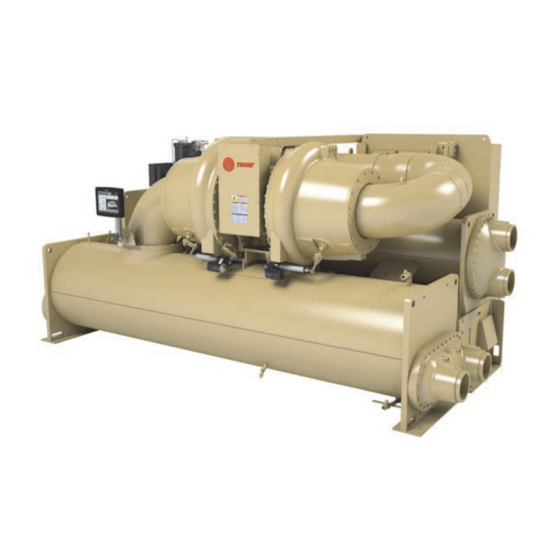
CVHM Water-cooled CenTraVac™
Chillers
Disassembly and Reassembly Units
Model
CVHM
Only qualified personnel should install and service the equipment. The installation, starting up, and servicing of
heating, ventilating, and air-conditioning equipment can be hazardous and requires specific knowledge and training.
Improperly installed, adjusted or altered equipment by an unqualified person could result in death or serious injury.
When working on the equipment, observe all precautions in the literature and on the tags, stickers, and labels that are
attached to the equipment.
August 2020
SAFETY WARNING
CVHM-SVN001C-EN
X39641319003
Advertisement
Table of Contents

Related Manuals for Trane CenTraVac CVHM


Summary of Contents for Trane CenTraVac CVHM
- Page 1 Installation Instructions CVHM Water-cooled CenTraVac™ Chillers Disassembly and Reassembly Units Model CVHM X39641319003 SAFETY WARNING Only qualified personnel should install and service the equipment. The installation, starting up, and servicing of heating, ventilating, and air-conditioning equipment can be hazardous and requires specific knowledge and training. Improperly installed, adjusted or altered equipment by an unqualified person could result in death or serious injury.
-
Page 2: Introduction
Carbon (HCFCs). Not all refrigerants containing these Labeling of Chemicals) guidelines for information on compounds have the same potential impact to the allowable personal exposure levels, proper environment. Trane advocates the responsible handling of respiratory protection and handling instructions. all refrigerants-including industry replacements for CFCs •... - Page 3 Disassembly and Reassembly • Non-Trane personnel should always follow local When a new chiller is shipped and received from our Trane regulations. manufacturing location and, for any reason, it requires disassembly or partial disassembly, and reassembly— which could include but is not limited to the evaporator,...
- Page 4 Copyright This document and the information in it are the property of Trane, and may not be used or reproduced in whole or in part without written permission. Trane reserves the right to revise this publication at any time, and to make changes to its content without obligation to notify any person of such revision or change.
-
Page 5: Table Of Contents
Table of Contents Introduction ......2 Components and Weights ....6 Components . -
Page 6: Components And Weights
Components and Weights Components Important: All fasteners are metric except waterbox and oil system hardware. Note: Use only new O-rings and gaskets. Do NOT reuse O-rings or gaskets. Figure 1. CVHM components (page 1 of 2) Motor Casting Compressor Base Condenser Detail A Motor Cooling... - Page 7 Components and Weights Figure 1. CVHM components (page 2 of 2) Volute Discharge Wrap Around Pipe Volute Discharge See Detail A (Drive Removed for Clarity) Condenser Discharge Connection (Drive Removed for Clarity) CVHM-SVN001C-EN...
- Page 8 Components and Weights Figure 2. CVHM drive dimensions, in. 8-13/16 51-5/16 6-1/8 1-3/8 34-1/16 1-3/4 35-7/16 1-11/16 72-5/16 1-7/8 15-11/16 5-5/8 CENTER OF GRAVITY 56-5/8 10 TO 12 CENTER OF GRAVITY 26 TO 31 Note: The holes on the top of the drive can be used for lifting the drive.
-
Page 9: Maximum Component Weights
Operating (Estimated) 26728 12060 Important: Two M20 swivel D-rings are required for lifting the compressor assembly (metric threads). Note: Wrap pipe requires three 5/8-in. shackles. Trane recommends using Crosby screw pin shackles, model S-209, stock number 1018482 with 5/8-in. pin. CVHM-SVN001C-EN... -
Page 10: Disassembly
Do not reuse oil that has been opened. • Change the compressor oil; the contractor should assist a qualified Trane Technician with this responsibility • Evacuate the chiller under 1000 microns; the contractor should assist a qualified Trane Technician with this responsibility CVHM-SVN001C-EN... -
Page 11: Wiring Disassembly
Contact your must be capable of supporting the entire weight of the local Trane Service office for assistance if required. component. Lifting cables (chains or slings) may not be This manual discusses a typical disassembly process. -
Page 12: Purge Unit Removal
Disassembly Important: In cases where the unit is being installed through restricted spaces, the oil tank filter WARNING may need to be temporarily removed. Prior Refrigerant under Positive Pressure! to removal of the filter, switch the regulator to the “change filter” setting. After the filter Failure to follow instructions below could result in an explosion which could result in death or serious injury has been removed from the regulator block,... -
Page 13: Control Panel Removal
Reassemble the purge unit in reverse order when the tagout procedures to ensure the power cannot be process is complete. inadvertently energized. For variable frequency drives or other energy storing components provided by Trane Figure 3. Purge unit or others, refer to the appropriate manufacturer’s literature for allowable waiting periods for discharge of capacitors. -
Page 14: Tracer Adaptiview Display Arm Removal
For variable frequency drives Recover refrigerant to relieve pressure before opening or other energy storing components provided by Trane the system. See unit nameplate for refrigerant type. Do or others, refer to the appropriate manufacturer’s... - Page 15 Disassembly Note: Cover all open connections to avoid prolonged equipped. See “Control Panel Removal,” p. 13 exposure of oil to humid air. Remove oil if a chiller instructions. is kept in a disassembled condition for an extended 4. Remove the economizer vent pipe flange bolts at the time.
- Page 16 Disassembly 8. Use designated lift point for level lift. Figure 10. Lifting clevis on the suction elbow lifting tab a. If the wrap pipe is still on the unit, see Figure b. If lifting the compressor only (no wrap pipe), see Figure Figure 11.
-
Page 17: Economizer Removal
Disassembly Loosen the bolts on the evaporator liquid line flange. NOTICE: Figure 14. Do not remove the bolts at this time. Handle with Care! Figure 14. Evaporator-Condenser-Economizer line flanges Failure to follow instructions below could result in equipment damage. The cast iron base of the compressor and the discharge flange of the volute can be broken easily if rough handling of the compressor/motor assembly is allowed. -
Page 18: Condenser/Evaporator Disassembly
Disassembly 11. Torque all bolts to specifications. Consult with your 5. Torque all bolts to specifications listed in Table 2, p.20. Trane service group for specific torques for your Figure 16. Separable shell unit (flange connection) economizer design. Condenser/Evaporator Disassembly... -
Page 19: Reassembly
This is the only sealing compound Joint Sealant placed approximately recommended by Trane for use on O-ring joints. To use 1/8-in. in board of the O-ring groove. This is used in this sealing compound, apply a light bead addition to the O-ring. -
Page 20: Tightening Flanges
14. Reconnect the previously cut compressor supply and Figure 18. Installation of 1/8-in. GORE-TEX tape return lines, oil supply and return lines, and the motor cooling lines using the factory-supplied couplings. Tightening Flanges Flanges with 8 or 12 Bolts Tighten all bolts to a snug tightness, following the numerical sequence for the appropriate bolt pattern as shown below. -
Page 21: Brazing
After the chiller has been moved to the equipment room and reassembled under Trane supervision, leak testing, WARNING and evacuation can be performed by Trane or under Trane Hazard of Explosion and Deadly Gases! supervision. Upon verification of leak tightness, installation can proceed for unit piping, wiring, etc. - Page 24 For more information, please visit trane.com or tranetechnologies.com. Trane has a policy of continuous product and product data improvement and reserves the right to change design and specifications without notice. We are committed to using environmentally conscious print practices.
Need help?
Do you have a question about the CenTraVac CVHM and is the answer not in the manual?
Questions and answers