Advertisement
Table of Contents
- 1 Warnings and Cautions
- 2 Table of Contents
- 3 General Information
- 4 Unit Control Panel (UCP)
- 5 Operator Interface
- 6 Chilled Water Setpoint
- 7 Inter Processor Communication (IPC)
- 8 Control System Components
- 9 Controls Sequence of Operation
- 10 Machine Protection and Adaptive Control
- 11 Unit Startup
- 12 Unit Shutdown
- 13 Periodic Maintenance
- 14 Oil Maintenance
- 15 Maintenance
- 16 Forms
- Download this manual
Advertisement
Table of Contents

Subscribe to Our Youtube Channel
Related Manuals for Trane CenTraVac Duplex CDHF


Summary of Contents for Trane CenTraVac Duplex CDHF
- Page 1 Operation Maintenance Duplex CDHF, CDHG ™ Water Cooled CenTraVac With CH530 CDHF-SVU01C-EN X39640670030...
-
Page 2: Warnings And Cautions
Warnings and Cautions Warnings and Cautions death, while cautions are designed to alert personnel to conditions that Notice that warnings and cautions could result in equipment damage. appear at appropriate intervals throughout this manual. Warnings Your personal safety and the proper are provided to alert installing operation of this machine depend contractors to potential hazards that... -
Page 3: Table Of Contents
Contents Warnings and Cautions General Information Unit Control Panel (UCP) Operator Interface Chilled Water Setpoint Inter Processor Communication (IPC) Control System Components Controls Sequence of Operation Machine Protection and Adaptive Control Unit Startup Unit Shutdown Periodic Maintenance Oil Maintenance Maintenance Forms CDHF-SVU01C-EN... -
Page 4: General Information
General Information Unit Nameplate Literature change 3. Product Coding Block The CDHF and CDHG models are Applicable to CDHF, CDHG The unit nameplate is located on the defined and built using the product About this manual left side of the unit control panel. definition and selection (PDS) The following information is Operation and maintenance... - Page 5 General Information Model Number - An example of a 3 = Condenser Tube Bundle Size M = 716 KW typical duplex centrifugal chiller 1 = 2100 nominal ton condenser N = 799 KW model number is: 2 = 2300 nominal ton condenser P = 892 KW 3 = 2500 nominal ton condenser R = 403 KW...
- Page 6 General Information C = Control: Condenser V = 1890 Refrigerant Pressure; W = 2060 0 = None, C = with X = 1475 Z = 560 - 3 stage 935 - 2 stage 1 = Control: Extended Operation; Y = 500 - 3 stage 835 - 2 stage 0 = None 1 = 630 - 3 stage 2245 - 2 stage 1 = Extended operation...
- Page 7 General Information Commonly Used Acronyms HVAC = Heating, Ventilating, and Air Control Optional Packages Conditioning For convenience, a number of OPST Operating Status Control acronyms are used throughout this IE = Internally-Enhanced Tubes GBAS Generic Building Automation manual. These acronyms are listed IPC = Interprocessor Communication Interface alphabetically below, along with the...
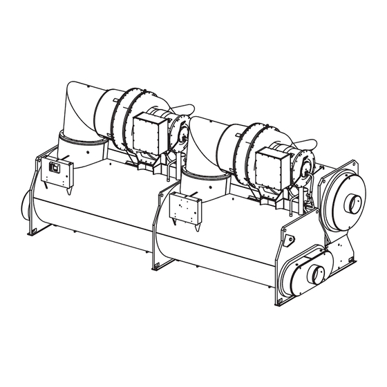
- Page 8 General Information Overview • Compressors and Motor 1 (Left hand), and 2 (Right hand) CDHF - CDHG • Economizers 1(LH), and 2 (RH), See Figure 1 for General Unit • Purge 1(LH), and 2 (RH), components. Each Chiller unit is •...
- Page 9 General Information Figure 2. General Duplex unit components (2 stage compressor) CDHF-SVU01C-EN...
- Page 10 General Information Cooling Cycle Here, the refrigerant gas is again Compressor 1 or 2 (2 Stage) compressed, and then discharged Compressed gas from the first-stage Duplex Chillers have two refrigerant through the third-stage variable guide impeller is discharged through the circuits that operate as their own vanes and into the third stage second-stage variable guide vanes...
- Page 11 General Information Figure 3. Pressure enthalpy curve (3 stage compressor) Figure 4. 2-stage economizer (3 stage compressor) CDHF-SVU01C-EN...
- Page 12 General Information Figure 5. Pressure enthalpy curve (2 stage compressor) Figure 6. Single stage economizer (2 stage compressor) CDHF-SVU01C-EN...
- Page 13 Any PC that meets the system appropriate information. requirements may download the service interface software and Tracer CH530 updates. For more information on TechView ™ visit your local Trane Service company, or The Trane Company’s website at www.trane.com. CDHF-SVU01C-EN...
- Page 14 General Information The large timeline cylinder indicates CTV Duplex Sequence Of Operation Power Up Diagram: This section will provide basic the upper level operating mode, as it The Power up chart shows the information on chiller operation for would be viewed on DynaView. Text respective DynaView screens during common events.
- Page 15 General Information Figure 8. CDHE/F/G sequence of operation: auto to running Figure 9. CDHE, CDHF, and CDHG sequence of operation: running This diagram shows the sequence of operations for a start of the first compressor on a duplex chiller. The ‘First’...
- Page 16 General Information Staging Second Compressor Off: This diagram shows the sequence of operations where there is no longer a need to run the ‘Second’ compressor, so it is staged off. The ‘First’ and ‘Second’ compressor will be determined by the type of duplex start selected Figure 10.
- Page 17 General Information Duplex Compressor Sequencing Fixed Sequence – Compressor 1/ adjustable (via service tool) (default = Four methods (Two fixed sequence Compressor 2 (Default mode) 30%, range from 0 to 50%). methods, a balanced start and hour’s If the chiller is in the Auto mode and Compressor 2 will be shut down and method, and a no staging method) all interlocks have been satisfied,...
- Page 18 General Information Fixed Sequence – Compressor 2 / starts. Both compressors will run If chilled water reset is used, the upstream compressor usually will be Compressor 1 until chiller average capacity drops the most efficient compressor to If the chiller is in the Auto mode and below Stage off Load point for 30 operate at part load.
- Page 19 General Information Sequencing - Balanced Starts and restart inhibit) or a circuit diagnostic, Hours then the other compressor will be When desired to balance the wear started. The second compressor will between the compressors. This stage on when chiller capacity method will extend the time between exceeds the Stage on Load point for maintenance on the lead compressor.
- Page 20 General Information Simultaneous Compressor Start/ If the chiller is in the Auto mode and Stop all interlocks have been satisfied, Both compressors will start in close compressor 1 will be started based succession to minimize the time it on the leaving water temperature takes for the chiller to reach full load.
- Page 21 General Information Compressor Load Balancing Restart Inhibit Start to Start Time Duplex chillers with CH530 control Setting will balance the compressor load by This setting defines the shortest giving each compressor the same chiller cycle period possible after the load command. The load command free starts have been used.
- Page 22 General Information Oil and Refrigerant Pump To ensure proper lubrication and A dual eductor system is used to prevent refrigerant from condensing reclaim oil from the suction cover Compressor Lubrication System - in the oil tank, a 750-watt heater is and the evaporator, and deposit it A schematic diagram of the immersed in the oil tank and is used...
- Page 23 General Information Figure 16. Oil refrigerant pump - circuit 1 or 2 CDHF-SVU01C-EN...
- Page 24 General Information Base Loading Control If the current exceeds the setpoint, input, an analog input, is at 1A17 the current limit algorithm unloads. terminals J2 – 1 and 3 (Ground) Algorithm: The “Capacity Limited By High which sets the external base loading This feature allows an external Current”...
- Page 25 General Information Figure 17. Base loading with external mA input and with external voltage input CDHF-SVU01C-EN...
- Page 26 General Information Ice Machine Control Figure 18. Sequence of operation: ice making: running to ice making UCP provides a service level “Enable or Disable” menu entry for the Ice Building feature when the Ice Building option is installed. Ice Building can be entered from “Front Panel”, or if hardware is specified the UCP will accept either an isolated contact closure (1A19 Terminals J2-1...
- Page 27 General Information Hot Water control ™ The DynaView Main Processor the external chilled water setpoint is provides the hot water temperature the external hot water setpoint; that Occasionally CTV chillers are control mode as standard. The is, a single analog input is shared at selected to provide heating as a leaving condenser water temperature the 1A16 –J2-1 to J2-3 (ground)
-
Page 28: Unit Control Panel (Ucp)
Unit Control Panel (UCP) Control Panel Devices and Unit The UCP houses several other controls modules called panel Mounted Devices mounted LLID (Low Level Intelligent Unit Control Panel (UCP) Device), power supply, terminal Safety and operating controls are block, fuse, circuit breakers, and housed in the unit control panel, the transformer. - Page 29 Unit Control Panel (UCP) Tracer CH530 Chiller Controller conditions, Tracer CH530 water flow current. Every five seconds then a sensing option accommodates multiple objective algorithm Revolutionary control of the chiller, variable evaporator water flow and its compares each parameter to its chilled water system, and your entire effect on the chilled water programmed limit.
-
Page 30: Operator Interface
Operator Interface Figure 21. DynaView ™ main processor ™ DynaView presents three menu tabs across the top which are labeled “MAIN, REPORTS, and SETTINGS”. The Main screen provides an overall high level chiller status so the operator can quickly understand the mode of operation of the chiller. - Page 31 Operator Interface ™ Spin values (up or down) are a The main body of the screen is used DynaView (DV) is the operator graphical user interface model used interface of the Tracer CH530 control for description text, data, setpoints, to allow a continuously variable system utilized on the CTV machine.
- Page 32 Operator Interface The Auto and Stop keys are used to How It Works selected key will be dark. The chiller put the unit into the auto or stop This new feature will be activated will stop when the Stop key is modes.
- Page 33 Operator Interface Figure 22 The machine-operating mode indicates the operational status of the chiller. A subscreen with additional mode summary information will be provided. When the user scrolls down the screen the Machine Operation Mode will remain stationary On DynaView ™...
- Page 34 Operator Interface Figure 23 Reference Top Level Mode Sub Level Mode BAS Code SYSTEM RESET Boot & Application software part number, self-test, and configuration validity screens will be present. Stopped Local Stop Stopped Panic Stop Stopped Diagnostic Shutdown – Manual Reset Run Inhibit Ice Building Is Complete Run Inhibit...
- Page 35 Operator Interface Reference Top Level Mode Sub Level Mode BAS Code Waiting To Start Motor Temperature Inhibit: Motor Temperature / Inhibit Temperature Waiting To Start Restart Time Inhibit: MIN:SEC Waiting To Start High Vacuum Inhibit: Oil Sump Press / Inhibit Press Waiting To Start Low Oil Temperature Inhibit: Oil Temperature / Inhibit Temperature Waiting To Start...
- Page 36 Operator Interface Main Screen The main screen is provides “an overall view“ of the chiller performance in addition to the main and sub operating modes. The table below indicates other items found , when specified by options, that can be scrolled to via the up or down arrows.
- Page 37 Alarms enunciator. can cause a repeat failure. Contact override. An Alarm will take When an alarm is present, the alarm local Trane Service for assistance as precedence over any manual enunciator is present next to the Stop necessary.
-
Page 38: Chilled Water Setpoint
Operator Interface The chilled water reset status area in The active chilled water setpoint is the right most column will display the setpoint that is currently in use. It will be displayed to 0.1 degrees one of the following messages: Fahrenheit or Celsius. - Page 39 Operator Interface The active current limit setpoint is The left column text “Front Panel”, the current limit setpoint that is “BAS”, “External”, and “Active currently in use. It will be displayed Current Limit Setpoint” will always in percent RLA. Touching the double be present regardless of installation arrow to the left of the Active Current or enabling those optional items.
- Page 40 Operator Interface Reports To aid in comparing the status of When a report screen is selected, the both circuits, the heading on the appropriate circuit is displayed in the Reports list screen has buttons as screen heading as shown in the indicated in the table above (i.e., sample evaporator screen below: System, Ckt1, and Ckt2).
- Page 41 Operator Interface Report name: System Evaporator Description Resolution Units Dependencies 1. Evap Entering Water Temp + or – XXX.X Temperature 2. Evap Leaving Water Temp + or – XXX.X Temperature 3. Evap Water Flow Switch Status (Flow, No Flow) 4. Evap Differential Wtr Press XXX.X Diff Pressure If option installed...
- Page 42 Operator Interface Report name: System ASHRAE Chiller Log Description Resolution Units Dependencies 1. Current Time/Date XX:XX mmm dd, yyyy Date / Time 2. Chiller Mode: Enum 3. Active Chilled Water Setpoint: XXX.X Temperature 4. Active Current Limit Setpoint: % RLA 5.
- Page 43 Operator Interface Setting Tab screens provides a user Settings screen for standard CTV : the ability to adjust settings justified to support daily tasks. The layout provides a list of sub-menus, organized by typical subsystem. To change chilled water setpoint, first select the settings tab screen.
- Page 44 Operator Interface Chiller Description Resolution or (Enumerations), Default Units 1. Front Panel Control Type (Chilled Water, Hot Water), Chilled Water Enum 2. Front Panel Chilled Water Setpt + or – XXX.X Temperature 3. Front Panel Hot Water Setpt + or – XXX.X Temperature 4.
- Page 45 Operator Interface System Mode Overrides Description Resolution or (Enumerations), Default Units Monitor Value 1. Compressor XXX / (Auto,Manual [0-100] ), Auto Enum IGV % Open Control Signal Evap. LWT AFD Freq. 2. Evap Water Pump (Auto, On), Auto Enum 1) Evap Flow status 2) Override Tim e Remaining...
- Page 46 Operator Interface Each Settings Sub screen consists of a setpoints list and the current value. The operator selects a setpoint to change by touching either the description or setpoint value. Doing this causes the screen to switch to the Analog Settings Subscreen shown below.
- Page 47 Operator Interface Settings with buttons only [screen has no cancel or enter key] do accept the new selection immediately. Note: Radio 1 and Radio 2 refer to “touch sensitive buttons.” The labels depend upon the setting being controlled. The analog setting subscreen is similar but offers an Auto/Manual radio button and value setting.
- Page 48 Operator Interface The mode override analog setting subscreen is similar but offers an Auto or Manual radio button and value setting. An Auto or Manual selection is necessary set to the mode to override. An Enter and Cancel Key will allow the user to Enter or Cancel the entry.
- Page 49 Operator Interface The time setpoint screen with a 12-hour format is shown below: The user must select Hour, or Minute and then use the up or down arrows to adjust. Adjusting hours will also adjust am and pm. Note: The 24-hour format setpoint screen is similar with the am and pm not shown.
- Page 50 Operator Interface The DynaView ™ Display Touch Screen Lock screen is shown below. This screen is used if the Display and Touch Screen Lock feature is Enabled. 30 minutes after the last key stroke this screen will be displayed and the Display and Touch Screen will be locked out until “159enter”...
-
Page 51: Inter Processor Communication (Ipc)
Interprocessor Communication Control Panel Internally Inter Processor Node number zero is is a special node assignment that is reserved for mounted devices Communications IPC3 devices that are service selected. A For visual identification Internal When using Tracer CH530, you will LLID communicating on node Control Panel mounted devices are not be required to know all the... -
Page 52: Control System Components
Control System Components Figure 24. Control panel components layout CDHF-SVU01C-EN... - Page 53 Control System Components CDHF-SVU01C-EN...
- Page 54 Control System Components Control Panel Devices Standard Devices Controls Field Connection Description Package Purpose Point Terminals 1A1 Power Supply Standard Converts 24 vac to 24 vdc not for field use 1A2 Power Supply (as required) #2 Converts 24 vac to 24 vdc not for field use 1A3 Dual Relay Standard...
- Page 55 Control System Components auxiliary contacts 5K2 on terminals Chilled and Condenser Water auxiliary contacts 5K1 on terminals 1X1-5 and 1A6-J3-2. Proof of 1X1-6 and 1A6-J2-2. Flow Interlock Circuits condenser water flow for the Proof of chilled water flow for the condenser is made by the closure of evaporator is made by the closure of flow switch 5S2 and the closure of...
- Page 56 Control System Components EXOP Extended Operation Option The following modules (1A17, 1A18, and 1A19) are provide when this control package is specified. 1A5 Quad Relay EXOP Relay #4 Ice Building Relay J2-10 NO, J2-11 NC, Output module J2-12 common 1A17 Optional Dual Analog EXOP Signal #1 External Base Loading...
- Page 57 Control System Components TRMM TRM4 (Tracer Comm 4 interface) 1A14 Optional TRM4 Tracer Communications J2-1 COMM+, J2-2 COMM -J2-3, Communication COMM +J2-4, COMM -, Interface Module LCI-C CDRP (Condenser Refrigerant Pressure Output) 1A15 Optional Dual Analog CDRP Signal #2 Condenser Refrigerant J2-4 Output #2, J2-6 Ground Input/output Module Pressure output...
- Page 58 Control System Components CDRP Refrigerant Pressure Pressure based Temperature based With the Enhanced Protection EPRO On standard machines the Percent Output Option 1A15: option, a condenser pressure Condenser Pressure Indication Refrigerant Pressure Output can be Output is based on the Saturated transducer is installed and the configured at commissioning to Condenser Refrigerant and a...
- Page 59 Control System Components The “Minimum Delta Pressure “ is increments of 1 psid (1kPa). The B) Refrigerant Differential Pressure Indication Output: typically set to 0 psi and will then condenser refrigerant pressure is correspond to 2 vdc. The “Maximum based on the Condenser Refrigerant A 2 to 10 VDC analog output is Delta Pressure “...
- Page 60 Control System Components GBAS (Generic Building Automation System) 1A15 Optional Dual GBAS Signal #1 Percent RLA Compressor Output J2-1 Output #1, J2-3 Ground Analog Input/ output Module 1A16 Optional Dual GBAS Signal #1 External Current limit Setpoint J2-2 Input #1, J2-3 Ground Analog Input/ output Module 1A16 Optional Dual...
- Page 61 Inrush 27 VAC (RMS) ~ 30A (RMS) Power, 24 +/- 10 percent VDC, 60 mA 14 AWG maximum, Trane IPC3 protocol. J1-1 Power Output: Class II Voltage 24 Power, 24 +/- 10 percent VDC, 20 mA +24VDC, J1-2 Ground, J1-3 COMM + VDC, Rated Current 2.44 Amps.
- Page 62 14 AWG Relay #4 J2-10 NO, J2-11 NC, J2-12 common Power, 24 +/- 10 percent VDC, 40 mA maximum Trane IPC3 protocol. Relay Outputs: at 120 VAC: 7.2 Amps resistive, 2.88 Amps pilot duty, 1/3 1A14 Communication interface HP , 7.2 FLA, at 240 VAC: 5 Amps...
- Page 63 J2: 14 - 26 AWG with a maximum of two 14 AWG J2-2 Input #1 to J2-3 (Ground). J2-5 Input #2 to J2-6 (Ground). Power, 24 +/- 10 percent VDC, 60 mA maximum, Trane IPC3 protocol. CDHF-SVU01C-EN...
- Page 64 Unit mounted devices Pressure sensors EarthWise ™ Purge Oil tank sump 4R4 and oil pump Trane has also revolutionized its Vane Actuator Control discharge 4R3, evaporator and controller-integrated purge, which The Stepper Module within the condenser refrigerant pressure 4R22, features an automatic regeneration...
- Page 65 Control System Components CDHF-SVU01C-EN...
- Page 66 Control System Components CDHF-SVU01C-EN...
-
Page 67: Controls Sequence Of Operation
Control Sequence of Operation UCP and Wye-Delta Starter Electrical Sequence 1. Circuit Breaker 1Q1 which provides power to the starter Control Circuits This section will acquaint the module (2A1) relay outputs and the operator with the control logic Logic Circuits within the various High Pressure Cutout switch (3S1). - Page 68 Control Sequence of Operation When less than 5 seconds remain G. If no diagnostics are generated in K. The shorting contactor (2K3) is before compressor start, a starter test the above tests, the Stop Relay (2A1- opened through the opening of relay is conducted to verify contactor J10) is closed for 2 seconds and the 2A1-J4 100 msec after the closure of...
- Page 69 Control Sequence of Operation Now that the compressor motor 2. After the 50 seconds has elapsed, follow the same stop sequence as (4M1) is running in the ‘‘Delta’’ above except the chilled water pump the stop relay (2A1-J10) and the configuration, the inlet guide vanes relay (1A5-J2) will also open and stop condenser water pump relays (1A5-...
- Page 70 Control Sequence of Operation Figure 24. Test and start timing sequence Timing requirements to operate the “Stop”, “Start”, “Short”, “Transition”, and “Run” contact closure outputs are shown below. Prior to closing the “Short” contact, the transition complete input shall be verified to be open, otherwise an MMR diagnostic shall be generated.
- Page 71 Control Sequence of Operation Current passing through circuit pump starter relay (4K8), to the start breaker 1Q5 reaches 2 normally open windings of the refrigerant pump. parallel sets of contacts: those of When motor 4M3 first starts, current refrigerant and oil pump relay (1A7- draw is high: This causes current J2-5 to 1), and the 2K11 interlocking sensing relay 4K8 to close its...
-
Page 72: Machine Protection And Adaptive Control
Machine Protection and Adaptive Control Momentary Power Loss (MPL) interruptions can be damaging to the MPL’s greater than 2 or 3 cycles are Protection. motor and compressor if the chiller detected resulting in unit shut down. is reconnected to the line while the Disconnection from the line is Improved power measurement and motor and line phases do not match. - Page 73 Machine Protection and Adaptive Control Current Overload Protection Overload protection for the motor the compressor when the current exceeds the specified time-trip curve. starts based on the Maximum Time Motor currents are continuously The compressor overload time trip to Transition permitted for a monitored for over current protection curve is expressed as a percent of the particular motor .
- Page 74 Machine Protection and Adaptive Control Phase Loss Protection Current Limit Protection The Current Limit function uses a PID Loss of phase detection protects the algorithm (Similar to the Leaving Current Limit Protections exist to chiller motor from damage due to a Water Temperature control) that avoid motor current overload and single-phasing condition.
- Page 75 Machine Protection and Adaptive Control Differential to Start or Stop drop below setpoint and may even Softloading is not active during Ice cause the chiller to cycle off. Soft Making or during the Ice To normal The Differential to Start setpoint is loading prevents the chiller from Transition.
- Page 76 Machine Protection and Adaptive Control Evaporator Limit Evaporator Limit uses the Evaporator Cutout results in an automatically Refrigerant Temperature sensor in a resettable diagnostic (MAR). The Evaporator refrigerant temperature is ™ PID algorithm (Similar to the Leaving DynaView Operating Mode continuously monitored to provide a Water Temperature control) that indicates when the “Leaving Water...
- Page 77 Machine Protection and Adaptive Control Low Refrigerant Temperature tool will display a warning message Cutout such as “Warning: Adequate Antifreeze required” for any The purpose of the low evaporator Evaporator Refrigerant Temperature refrigerant temperature protection is to prevent water in the evaporator Cutout below 28°F and any Leaving Water Temperature Cutout below from freezing.
- Page 78 Machine Protection and Adaptive Control Figure 31. Cutout strategy Limit Loading: The potential to limit loading increases as the saturated evaporator temperature approaches the evaporator limit setpoint. Unload: The potential to unload increases as the saturated evaporator temperature falls further below the evaporator limit setpoint. Figure 31 illustrates these functions as follows: •...
- Page 79 Machine Protection and Adaptive Control Condenser Limit The Condenser Limit will be based Condenser pressure is continuously from a pressure conversion from the Condenser Refrigerant Temperature monitored to provide a limit function sensor, unless there is a Condenser that prevents High Pressure Cutout Refrigerant Pressure sensor installed (HPC) trips.
- Page 80 Machine Protection and Adaptive Control Restart Inhibit During the time the start is inhibited Restart Inhibit Start to Start Time due to the start-to-start timer, the Setting This function provides short cycle DynaView shall display the mode This setting defines the shortest protection for the motor, and ‘Restart Inhibit’...
- Page 81 Machine Protection and Adaptive Control If the oil temperature is at or below a High Vacuum Lockout given Low Oil Temperature Inhibit The oil sump pressure is below the setting (default 95°F/35°C) the lockout setpoint. Starting of compressor cannot be started. This compressor is inhibited as a result.
- Page 82 Machine Protection and Adaptive Control Oil Temperature Control If the oil temperature is at or above the High Oil Temperature Cutout The oil heater is used to maintain the setpoint this diagnostic will be issued oil temperature within +/- 2.5°F (1.4°C) - which will stop the compressor.
- Page 83 Machine Protection and Adaptive Control Controls Chilled Water Reset MAXIMUM RESET is a user The following equations and parameters apply for CWR. adjustable limit providing the (CWR) maximum amount of reset. For all Chilled water reset is designed for Return Water types of reset, CWS - CWS <...
- Page 84 Machine Protection and Adaptive Control Table 3. Values for start reset types Constant Return CWS’ = CWS + 100 percent The values for “RESET TYPE” are: (Design Delta Temperature) - (TWE- Reset Outdoor Return Const Return Type: Disable Air Reset Reset Reset TWL) and CWS’...
- Page 85 Machine Protection and Adaptive Control Reset Ratio: Start Reset = Outdoor Air Start Reset Reset Ratio = -70 percent The Reset Ratio is displayed as a Example of Calculating Reset for Start Reset = 90 percentage. To use it in the above Outdoor Air Temperature: TOD = 100 equation it must be converted to it’s...
- Page 86 Machine Protection and Adaptive Control Figure 33. Reset function for return CWR Figure 34. Reset function for return CWR Note: This graph assumes Maximum Reset is set to 20 degrees. CDHF-SVU01C-EN...
- Page 87 Machine Protection and Adaptive Control Example of Calculating Return Reset: How many Degrees of Reset will How many Degrees of Reset will there be? there be? Reset Ratio = 50% Degrees of Reset = Reset Ratio*(Start Degrees of Reset = Reset Ratio*(Start Start Reset = 25 Reset - (TWE-TWL)) Reset - (TWE-TWL))
- Page 88 Machine Protection and Adaptive Control Figure 35. Return CWR Figure 36. Constant CWR CDHF-SVU01C-EN...
-
Page 89: Unit Startup
Unit Startup Unit Start-Up Procedures The UCP also checks compressor Oil pressure must be verified within 3 motor winding temperature, and a minutes or a MMR diagnostic is Daily Unit Start-Up minimum restart time is initiated if generated. 1. Verify the chilled water pump and the winding temperature is less than When less than 5 seconds remain on condenser water pump starter are... - Page 90 Unit Startup When the cooling requirement is 4. Open all of the valves in the WARNING satisfied, the UCP originates a evaporator chilled water circuit. “Shutting down” signal. The inlet 5. If the evaporator was previously Live Electrical guide vanes are driven closed for 50 drained, vent and fill the evaporator seconds, and the unit enters a 3- Components!
-
Page 91: Unit Shutdown
Maintenance section of this pumps shutdown turn Pump manual should be performed by Contactors to OFF or open pump qualified Trane service technicians. disconnects. Note: During extended shutdown, be Seasonal Unit Shutdown sure to operate the purge unit for a 2- hour period every two weeks. -
Page 92: Periodic Maintenance
EN or the latest revision which can [ ] Check the chiller’s evaporator and [ ] Check the oil level in the chiller oil be obtained at the nearest Trane condenser pressures, oil tank sump using the two sight glasses office. - Page 93 [ ] Clean all water strainers in the energized. For variable frequency CenTraVac water piping system. drives or other energy storing Every 6 Months components provided by Trane or others, refer to the appropriate manufacturer’s literature for allowable waiting periods for discharge of capacitors. Verify with an appropriate voltmeter that all capacitors have discharged.
- Page 94 32°F (1° at 0°C)). If the evaporator and adding several drops of Trane heater warm and will also keep air refrigerant temperature displayed on OIL00022. Replace plug.
-
Page 95: Oil Maintenance
[ ] Pump the oil from the chiller A drain fitting is installed in the oil Note: Use only Trane OIL00022. A full through the oil charging valve into an filter top, after the oil filter, for oil change is 9 gallons of OIL00022. - Page 96 Oil Maintenance 4. Allow at least 15 minutes for the oil Replacing Oil Filter to drain from the filter back into Replace oil filter: (1) annually, (2) at the oil sump. each oil change, (3) or if erratic oil pressure is experienced during 5.
-
Page 97: Maintenance
For variable frequency [ ] Submit a sample of the 6. Using a grease gun with an drives or other energy storing compressor oil to a Trane qualified appropriate fitting, insert ONLY components provided by Trane or laboratory for comprehensive... - Page 98 Grease fittings are not few drops of Trane OIL00022 in the arms in order to test for a vacuum-tight and will become a leak cavity. Be sure to reinstall the pipe “hydraulically locked”...
- Page 99 The available pressure Note: If your chiller is covered by a and may be under positive pressure. differential. Trane extended warranty, the terms of Recover refrigerant to relieve c. Gravity. (Use a return vent line that warranty may require that the pressure before opening the system.
- Page 100 To leak-test a chiller containing full determine what water treatment, if refrigerant charge, raise chiller any, is required. Trane assumes no pressure using a controlled hot water responsibility for equipment failures or electric-resistance system to a which result from untreated or maximum of 8 psig.
- Page 101 For control calibration and check-out, to remove sludge and loose material Failure to follow proper procedures contact a Trane qualified service from smooth-bore tubes. could result in corrosion damage to organization. To clean other types of tubes the unit and tubes.
- Page 102 System contains oil and refrigerant engineer that handled the order. and may be under positive pressure. The Trane EarthWise Purge is the Recover refrigerant to relieve 4. The refrigerant charge should be only purge system available for the pressure before opening the system.
- Page 103 Maintenance WARNING IMPORTANT: DO NOT USE 11. Obtain an oil analysis initially UNTREATED OR IMPROPERLY after six months of storage, and TREATED WATER, OR EQUIPMENT once each succeeding year. If no Live Electrical DAMAGE MAY OCCUR. oil breakdown is evident do not Components! change the oil.
-
Page 104: Forms
CDHF-SVU01C-EN... - Page 105 CDHF-SVU01C-EN...
- Page 106 CDHF-SVU01C-EN...
- Page 107 CDHF-SVU01C-EN...
- Page 108 CDHF-SVU01C-EN...
- Page 109 CDHF-SVU01C-EN...
- Page 110 CDHF-SVU01C-EN...
- Page 111 CDHF-SVU01C-EN...
- Page 112 CDHF-SVU01C-EN...
- Page 113 CDHF-SVU01C-EN...
- Page 114 CDHF-SVU01C-EN...
- Page 115 CDHF-SVU01C-EN...
- Page 116 CDHF-SVU01B-EN 604 Stocking Location La Crosse Trane Trane has a policy of continuous product and product data improvement and reserves the right to change design A business of American Standard Companies and specifications without notice. www.trane.com For more information contact your local district office Only qualified technicians should perform the installation and servicing of equipment referred to in this publication.
Need help?
Do you have a question about the CenTraVac Duplex CDHF and is the answer not in the manual?
Questions and answers