Table of Contents
Advertisement
Quick Links
Installation, Operation, and Maintenance
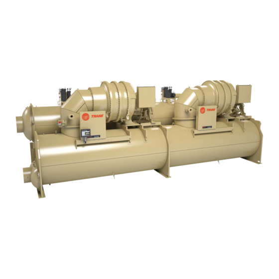
CenTraVac™ Water-cooled Chillers
Model CDHH
With Symbio™ Controls
Model: CDHH
Only qualified personnel should install and service the equipment. The installation, starting up, and servicing of heating, ventilating, and air-conditioning equipment
can be hazardous and requires specific knowledge and training. Improperly installed, adjusted or altered equipment by an unqualified person could result in death or
serious injury. When working on the equipment, observe all precautions in the literature and on the tags, stickers, and labels that are attached to the equipment.
April 2023
SAFETY WARNING
CDHH-SVX003C-EN
X39641418003
Advertisement
Table of Contents

Related Manuals for Trane CenTraVac CDHH


Summary of Contents for Trane CenTraVac CDHH
- Page 1 Installation, Operation, and Maintenance CenTraVac™ Water-cooled Chillers Model CDHH With Symbio™ Controls Model: CDHH X39641418003 SAFETY WARNING Only qualified personnel should install and service the equipment. The installation, starting up, and servicing of heating, ventilating, and air-conditioning equipment can be hazardous and requires specific knowledge and training. Improperly installed, adjusted or altered equipment by an unqualified person could result in death or serious injury.
- Page 2 (HCFCs). Not all refrigerants containing these compounds bump cap, fall protection, electrical PPE and arc have the same potential impact to the environment. Trane flash clothing). ALWAYS refer to appropriate advocates the responsible handling of all refrigerants.
- Page 3 Trane specifically authorized to perform startup). Additional Requirements for Units Requiring Disassembly and Reassembly When a new chiller is shipped and received from our Trane manufacturing location and, for any reason, it requires disassembly or partial disassembly, and reassembly—...
- Page 4 This document and the information in it are the property of • Updated Vent Line Sizing Reference section in Vent Trane, and may not be used or reproduced in whole or in Piping chapter. part without written permission. Trane reserves the right to...
-
Page 5: Table Of Contents
Installation: Mechanical ..... 21 Trane RuptureGuard ..... . 38 Operating Environment . - Page 6 Sensor Circuits ......72 CWR – Outdoor Option ....75 Trane-supplied Remote Starter Wiring ..54 Optional Control and Output Customer-supplied Remote Starter Circuits .
- Page 7 Recommended Maintenance ....103 and Request for Trane Service ... . . 116 Record Keeping Forms ....103 Appendix C: CenTraVac™...
-
Page 8: Unit Nameplate
Unit Nameplate The unit nameplate is located on the left side of the left Figure 1. Typical unit nameplate hand control panel. A typical unit nameplate is illustrated in the following figure and contains the following information: • Unit model and size descriptor •... -
Page 9: Compressor Nameplate
The model number begins with “CCHH” and the nameplate is located on the foot of the volute. MODEL NO. SERIAL NO. SALES ORDER TRANE MADE IN USA X39002458010B Note: The serial number space on the compressor nameplate will be intentionally left blank. - Page 10 Unit Nameplate Figure 4. PED nameplate (all dimensions are metric) CDHH-SVX003C-EN...
-
Page 11: Model Number Descriptions
Model Number Descriptions CDHH CenTraVac Chiller Description Digit 1, 2 — Duplex™ CenTraVac™ Chiller Digit 33, 34 — Condenser Orifice Size (RH Circuit) Digit 3 — Direct Drive Digit 35 — Unit Option Digit 4 — Development Sequence Digit 36 — Control: Enhanced Protection Digit 5, 6, 7 —... -
Page 12: Cchh Centrifugal Compressor
Model Number Descriptions CCHH Centrifugal Compressor compressor parts. The model number begins with “CCHH” and the nameplate is located on the foot of the volute. Description The compressor assembly has a separate model number which is required to identify internal and external Digit 1, 2 —... -
Page 13: Pre-Installation
If • A refrigerant monitor or detector that is capable of the charge has escaped, contact your local Trane monitoring and alarming within the acceptable sales office for instructions. For Duplex™, verify exposure level of the refrigerant, and that can actuate charge on both units. -
Page 14: Installation Requirements And Contractor
Foundation • Safety chains Rigging • Rigging shackles • Lifting beam Trane will perform or have direct on-site supervision of the Disassembly/Reassembly disassembly and reassembly work (as required) (contact your local Trane office for pricing) • Isolation pads or spring isolators •... -
Page 15: Storage Requirements
Start-up must be performed by Trane or an agent of Trane specifically authorized to perform start-up and warranty of Trane® products. Contractor shall provide Trane (or an agent of Trane specifically authorized to perform start-up) with notice of the scheduled start-up at least two weeks prior to the scheduled start-up. - Page 16 If no oil analysis program has been followed, replace oil prior to start-up If the chiller will be stored for more than six months after production, contact your local Trane Service Agency for required extended storage actions to minimize impact to the chiller and preserve the warranty.
-
Page 17: Unit Components
Pre-Installation Unit Components of the unit is referred to as referred to as Side 1 and the right side of the unit is referred to as Side 2. Note: The control panel side of the unit is always designated as the front side of the unit. The left side Figure 6. -
Page 18: Unit Clearances And Weights
Unit Clearances and Weights Recommended Unit Clearances • Use a housekeeping pad to provide better service clearances; refer to submittal for more information. Adequate clearances around and above the chiller are Per National Electric Code (NEC) Article 110: Unit mounted required to allow sufficient access for service and starters from 0 to 600V require a 42 inch (107 cm) maintenance operations. -
Page 19: General Weights
For specific Important: The weight information provided here should be weights for your chiller, refer to your submittal used for general information only. Trane does package. not recommend using this weight information for considerations relative to chiller handling, Table 2. -
Page 20: Weights (Kg)
Important: The weight information provided here should be recognized in these tables. For specific used for general information only. Trane does weights for your chiller, refer to your submittal not recommend using this weight information package. -
Page 21: Installation: Mechanical
Each of the protected from freezing. Freeze damage from an cables (chains or slings), hooks, and shackles used to unheated equipment room is not the Trane company's lift the unit must be capable of supporting the entire responsibility. These are indoor units. - Page 22 Installation: Mechanical 4. Position isolator pads or spring isolators beneath the 5. Once the isolators are in place, lower the chiller— chiller feet (refer to “Unit Isolation,” p. 23 working from end to end—in small increments to instructions).Follow instructions provided by the spring maintain stability.
-
Page 23: Special Lift Requirements
Do NOT fork-lift the unit. Special Lift Requirements Note: Disassembly and reassembly work includes dowel-pinning the compressor and removing it NOTICE from the unit. Contact Trane or an agent of Trane specifically authorized to perform start-up and Oil Loss! ® warranty of Trane... -
Page 24: Isolation Pads
Specific isolator loading data is provided in the unit Remember that the chiller must be level within 1/16 in. submittal package. If necessary, contact your local Trane (1.6 mm) over its length and width after it is lowered onto sales office for further information. -
Page 25: Leveling The Unit
Installation: Mechanical Note: Fastening the isolators to the floor is not Figure 11. Chiller foot and isolator orientation necessary unless specified. 4. If the chiller must be fastened to the isolators, insert Center cap screws through the chiller base and into holes tube sheet Outside drilled and tapped in the upper housing of each isolator. - Page 26 Figure 12. Leveling the chiller Note: Use of a laser level is an acceptable alternative Important: Immediately report any unit damage incurred method to level the unit. during handling or installation at the job site to the Trane sales office. CDHH-SVX003C-EN...
-
Page 27: Installation: Water Piping
Failure to follow instructions could result in possible tube damage. equipment damage. Important: Trane strongly recommends using the services Do NOT allow chiller to freeze! Bundles must be of a qualified water treatment specialist to drained and air-blown dry if chiller is stored in an determine necessary water treatment. -
Page 28: Strainers
To prevent components damage, pipe strainers must located in control panel. be installed in the water supplies to protect components from water borne debris. Trane is not responsible for equipment-only-damage caused by water borne debris. Install a strainer in the entering side of each piping circuit to avoid possible tube plugging in the chiller with debris. - Page 29 “4” in the preceding figure). Refer to the Note: The “Temp” potentiometer on the ifm efector® following figure for cable wiring. control module has no effect in Trane application. It is NOT necessary to make adjustments to the NOTICE “Temp”...
-
Page 30: Evaporator And Condenser Water
These baffles are designed for a maximum pressure of 20 psid (137.9 kPaD). If larger pressure drops are expected in the application, contact your local Trane representative to discuss special waterbox options. Important: Water flows must be piped in accordance with nameplate designation. -
Page 31: Water Piping Connections
Note: If needed, plug-type sensor extension cables are for-end, be sure to reinstall them right-side up to maintain available for purchase from Trane Parts Service. the correct baffle arrangements. Use a new gasket with These sensor extension cables may be necessary if each waterbox cover. -
Page 32: Flange-Connection Adapters
Unit Model Type ® Flanged Victaulic Customer provided No adapter Flanged (optional) CDHH ® Victaulic required coupling Customer Trane provided provided ® ® Victaulic (all others) Victaulic -to- CDHH ® Victaulic flange adapter coupling Figure 18. Customer piping connection types Flanged Victaulic®... -
Page 33: Victaulic Gasket Installation
Installation: Water Piping Victaulic Gasket Installation 6. Tighten fasteners alternately and equally until housing screw pads are firmly together (metal-to-metal); refer to 1. Inspect supplied gasket to be certain it is suited for “Screw-Tightening Sequence for Water Piping intended service (code identifies gasket grade). Apply a Connections,”... -
Page 34: Pressure Testing Waterside Piping
(1034.2 kPaG) or 300 psig (2068.4 kPaG); refer to unit nameplate or to submittal documentation. Eddy Current Testing Trane recommends conducting an eddy current inspection of the condenser and evaporator tubes in water-cooled chillers every three years. Eddy current tests are intended to identify defects on or within the walls of heat exchanger tubing that could lead to in-service tube failures. -
Page 35: Vent Piping
When pressure-relief valves and NOT to balanced relief considering a vent system constructed of plastic valves, rupture members (as used on Trane® piping such as PVC, ensure that both the pipe centrifugal chillers), fusible plugs, or pilot-operated material and the adhesive have been tested for valves. -
Page 36: Vent Line Installation
Vent Piping Note: The tables and figures in “Vent Line Sizing • When attaching the vent line to the chiller, do NOT Reference,” p. 39 are applicable only for non- apply threading torque to the outside pipe of the rupture manifolded vent-line runs connected to a 50 psig disk assembly. - Page 37 The drip leg must be drained periodically to assure that it does not overflow and allow fluid to flow into the horizontal portion of the vent line. Trane assumes no responsibility for equipment damage caused by insufficient drainage of drip leg.
-
Page 38: Trane Ruptureguard
The Trane RuptureGuard™ refrigerant containment system overflow and allow fluid to flow into the horizontal replaces the carbon rupture disk on new low pressure portion of the vent line. Trane assumes no chillers utilizing R-1233zd. The RuptureGuard™ consists of responsibility for equipment damage caused by a solid-metal, (non-fragmenting) reverse-buckling rupture insufficient drainage of drip leg. -
Page 39: Vent Line Sizing Reference
9 in. that result from a failure to properly install the (22.86 cm) of valve discharge. Refer to ASHRAE RuptureGuard™ will NOT be paid by Trane. Standard 15, national, state, and local codes for additional requirements on piping rupture disk Vent Line Sizing Reference and relief valve vent lines. - Page 40 Vent Piping Figure 28. Rupture disk vent pipe sizing (IP units); for use with preceding table Pipe size as a Function of “C” Value and Length of Run 1000 Pipe Size (I.D.) Friction Factor 6 NPS 6.06 in. f = 0.0149 5 NPS 5.05 in.
- Page 41 Vent Piping ASHRAE Standard 15 – If chiller uses a rupture disk: = (0.5 P) + atmospheric pressure 0.214d – P d * ln(P Table 14. “C” values used to determine rupture disk – vent line sizes (kg/s); for use with the following figure •...
- Page 42 Vent Piping Figure 29. Rupture disk vent pipe sizing (SI units); for use with preceding table Pipe size as a Function of “C” Value and Length of Run Pipe Size (I.D.) Friction Factor 150 DN 154 mm f = 0.0149 125 DN 128 mm f = 0.0155...
- Page 43 Vent Piping ASHRAE Standard 15 • d = inside diameter of pipe or tube, mm • ln = natural logarithm –15 7.4381x10 – P d * ln(P • = absolute pressure at outlet of discharge piping, – kPa (atmospheric pressure) 500f •...
-
Page 44: Insulation
75 percent relative humidity Factory-applied Insulation Operation outside of normal design conditions as defined in this section may require additional insulation; contact Trane All low-temperature surfaces are covered with 3/4 in. for further review. (19.05 mm) Armaflex® II or equal (thermal conductivity = 0.25 Btu/h-ft... - Page 45 Insulation Figure 30. Recommended area for unit insulation Line to eductor Line from evaporator Filter drier and eductor lines Suction cover Suction elbow Suction Control connection panel Pipe support Economizer Pipe Evaporator See first See first Eductor See first two notes note line two notes...
-
Page 46: Installation: Controls
® Tracer TU serves as a common interface to all Trane chillers, and will customize itself based on the properties of the chiller with which it is communicating. Thus, the service technician learns only one service interface. -
Page 47: Control Panel
Installation: Controls Control Panel Figure 32. Control panel: main unit assembly left hand panel (showing low voltage and higher voltage areas for proper routing of field wiring) 30 Volt Maximum 30–115 Volt Maximum CDHH-SVX003C-EN... - Page 48 Installation: Controls Figure 33. Control panel: main unit assembly right hand panel (showing low voltage and higher voltage areas for proper routing of field wiring) 30 Volt Maximum 30–115 Volt Maximum CDHH-SVX003C-EN...
-
Page 49: Installing The Tracer ® Adaptiview
AdaptiView™ display with the LCD screen facing up on top of the display support arm base plate. Note: Ensure the Trane logo is positioned so that it will be at the top when the display is attached to the display support arm. -
Page 50: Display Arm
Installation: Controls Figure 36. Display attachments to the support arm To adjust the tension on the display arm: base plate • At each joint in the display arm, there is either a hex bolt (1 and 2) or hex screw (3). Turn the hex bolt or screw in the proper direction to increase or decrease tension. -
Page 51: Module Installation
Installation: Controls Module Installation ® Recommended routing from Air-Fi module to Symbio™ 800 using factory provided mounting provision is shown in ® Air-Fi figure below. Device can be remote mounted in order to obtain a stronger signal. ® For installation instructions, see BAS-SVN038*-EN, Air-Fi Wireless Communications Interface (WCI) Installation Instructions. -
Page 52: Wi-Fi
Recommended routing from Wi-Fi module to Symbio™ 800 using factory provided mounting provision is shown in ® For installation instructions, see BAS-SVN042*-EN, Trane figure below. Device can be remote mounted in order to Wi-Fi Module Installation Instructions. obtain a stronger signal. -
Page 53: Electrical Requirements
Electrical Requirements Installation Requirements local, state, and national codes. For the USA, be sure to satisfy proper equipment grounding requirements WARNING per NEC. Proper Field Wiring and Grounding • Compressor motor and unit electrical data (including motor kW, voltage utilization range, rated load amps, Required! and locked rotor amps) is listed on the chiller Failure to follow code could result in death or serious... -
Page 54: Trane-Supplied Remote Starter Wiring
For variable frequency drives Wiring or other energy storing components provided by Trane or others, refer to the appropriate This information is applicable to Starter 1 for Compressor 1 manufacturer’s literature for allowable waiting periods as well as Starter 2 for Compressor 2. (For wire estimation for discharge of capacitors. - Page 55 -installed. Refer to submittal and ship-with wiring schematics for voltage requirements. Must be separated from 120 Vac and higher wiring. The maximum distance a Trane–supplied remote starter can be placed from the chiller is 1000 ft (305 m). CDHH-SVX003C-EN...
- Page 56 , refer to the table in “Electrical Requirements,” p. Starter by Others Specification available from your local Trane sales office. Wires, lugs, and fuses/breakers are sized based on National Electric Code (NEC) [NFPA 70] and UL 1995. Refer to submittal and ship-with wiring schematics for voltage requirements.
-
Page 57: Current Transformer And Potential
Customer-supplied Remote Starter Wiring Current Transformer and Table 20. Maximum recommended total wire length for potential transformers (PTs) in a single Potential Transformer Wire PT system Sizing Maximum Lead Length Wire AWG For customer-supplied starter-to-chiller unit control panel Feet Meters starter module 1K23;... -
Page 58: Power Supply Wiring
Power Supply Wiring NOTICE WARNING Adaptive Frequency Drive (AFD)/Starter Proper Field Wiring and Grounding Component Damage! Required! Failure to remove debris from inside the AFD/starter Failure to follow code could result in death or serious panel could result in an electrical short and could injury. -
Page 59: Circuit Breakers And Fused
L1 L2 L3 G L1 L2 L3 G L1 L2 L3 G ® cables being used by customer to interface with the Trane chiller must be shielded Ethernet cabling. The customer is required to provide an overcurrent device upstream of the CPTR option in accordance with International Electrotechnical Commission (IEC) standards and/or any applicable local and national codes. -
Page 60: Ce For Starter Or Drive
• All Trane-supplied remote starters and wiring needs to be run in conduit. Any Ethernet cables drives used in conjunction with CDHH ® being used by customer to interface with the Trane chiller ® Trane chillers will be CE-compliant per must be shielded Ethernet cabling. -
Page 61: Control Power Transformer
Power Supply Wiring NOTICE Component Damage! Failure to follow instructions below could cause an electrical short which could result in component damage. Remove debris from inside the CPTR option enclosure panel before turning the power on. The standard unit-mounted CPTR option shall have an enclosure with a disconnect and will require customer- supplied power. - Page 62 For variable frequency drives or other energy storing components provided by Trane or others, refer to the appropriate manufacturer’s literature for allowable waiting periods for discharge of capacitors. Verify with a CAT III or IV voltmeter rated per NFPA 70E that all capacitors have discharged.
-
Page 63: Interconnecting Wiring
Power Supply Wiring Figure 42. Option 2—PFCC wires routed through Figure 43. Typical equipment room layout for units current transformers with unit-mounted starter Fused Disconnect or Suitable Current Breaker Transformer Power Motor Circuit Motor Starter Contactor 1. Line side power conduits Fuses Enclosed 2. -
Page 64: Starter To Motor Wiring
• Install but do NOT connect the power leads between the starter and compressor motor. (These connections will be completed under supervision of a qualified Trane service engineer after the pre-start inspection.) X39003892001A Note: Graphic labels (shown above) are used for CE application only. -
Page 65: Bus Bars
“Electrical Requirements,” p. 53. The Bus bars and extra nuts are available as a Trane option. polarity of the IPC wiring is critical for proper operation. Install the bus bars between the motor terminals when using a starter that is: •... - Page 66 Power Supply Wiring WARNING Important: • Before servicing, disconnect all power Proper Field Wiring and Grounding sources and allow at least 30 minutes for Required! capacitors to discharge. Failure to follow code could result in death or serious • All electrical enclosures—unit or remote— injury.
-
Page 67: Medium Voltage Motor
Frame 6800, 6800L nameplate for motor data including RLA, LRA, etc. 2300–13.8kV 117.3 Frame 440E, 5000, 5800, 580L In all cases of non-Trane supplied starters, a disconnecting 380–600 Vac means and short-circuit protection must be installed ahead 58.5 Frame 440E, 5000 of the starter, unless they are included as part of the starter. -
Page 68: Motor Supply Wiring
To limit the effects of corona or ionization with cables carrying more than 2000V, Trane requires that the power cable have a metallic shield, unless the cable is specifically listed or approved for non-shielded use. If the cable is shielded, the shielding must be grounded at one end (grounding is typically done at the starter or supply end). -
Page 69: Ground Wire Terminal Lug
To or other energy storing components provided by minimize the risk of possible fires, a floor plate Trane or others, refer to the appropriate of at least 0.056 in. (1.43 mm) thick galvanized manufacturer’s literature for allowable waiting periods or 0.63 in. -
Page 70: System Control Circuit Wiring
System Control Circuit Wiring (Field Wiring) Table 23. Unit control panel wiring 120 Vac Standard Control Circuits: Unit Control Panel Control Wiring Input or Output Type Unit Control Terminations Contacts (120 Vac) Chilled Water Flow Proving Input Binary Input Normally Open, Closure with Flow 1X1-5 to 1K16-J3-2 Left Panel Condenser Water Flow Proving Input Binary Input... -
Page 71: Water Pump Interlock Circuits And Flow
System Control Circuit Wiring (Field Wiring) Table 23. Unit control panel wiring 120 Vac (continued) ® Communication to BACnet ® ® (As Ordered; See Sales Order) BACnet or MODBUS 1K1–P1 Left Panel ® MODBUS ® (As Ordered; See Sales Order) LON Interface 1K25 Left Panel Communication to LonTalk... -
Page 72: Chilled Water Pump
System Control Circuit Wiring (Field Wiring) Chilled Water Pump separate 120-volt, single-phase power supply with 14 AWG, 600-volt copper wire. For AWG/MCM 1. Wire the evaporator water pump contactor (5K42) to a equivalents in mm , refer to the table in “Electrical separate 120 volt single-phase power supply with Requirements,”... - Page 73 System Control Circuit Wiring (Field Wiring) Figure 47. Device locations CDHH-SVX003C-EN...
- Page 74 System Control Circuit Wiring (Field Wiring) Figure 48. Device designators DEVICE DEVICE LEGEND DESCRIPTION DEVICE TYPE DESIGNATION ADAPTIVIEW DISPLAY MODULE DISPLAY MONITOR MOTOR WINDING TEMPERATURE 1 SENSOR - TEMP MOTOR WINDING TEMPERATURE 2 SENSOR - TEMP MOTOR WINDING TEMPERATURE 3 SENSOR - TEMP 4BP2 OIL PUMP DISCHARGE PRESSURE TRANSDUCER...
-
Page 75: Cwr - Outdoor Option
(IPC) bus is connected to the module for IPC. 24 Vdc power and the communications link. Trane recommends mounting the sensor module within the Optional Control and Output Circuits control panel and the sensor two wire leads be extended Install various optional wiring as required by the owner’s... -
Page 76: Operating Principles
By carefully reviewing this information and following the instructions given, the owner or operator can successfully operate and maintain the chiller. If mechanical problems do occur, however, contact a Trane service technician to ensure proper diagnosis and repair of the unit. -
Page 77: Duplex Compressor Sequencing
Operating Principles Fixed Sequence – Compressor 1 / (refer to the following figure). Notice that some of the liquid refrigerant flashes to a gas because of the pressure drop Compressor 2 (Default Mode) created by the orifice plate, thus further cooling the liquid If the chiller is in the Auto mode and all interlocks have refrigerant. -
Page 78: Hours
Operating Principles The default is 40 percent which means that a single Figure 55. Duplex™ chiller sequence of operation: equalize starts and hours compressor would have to load to 80 percent (the average would be 40 percent) before the second compressor starts. Both compressors will run until chiller average capacity Auto drops below stage-off load point for 30 seconds. -
Page 79: Stop
Operating Principles Simultaneous Compressor Start/Stop The operation of the restart inhibit function is dependent upon two setpoints. Both compressors will start in close succession to minimize Restart Inhibit Free Starts. The Restart Inhibit Free Starts the time it takes for the chiller to reach full load. Some (default = 3, range from 1 to 5) is adjustable via the service process applications need the chiller to start and generate tool and will allow a number of rapid restarts equal to its... - Page 80 Operating Principles Figure 58. Oil refrigerant pump Compressor lubrication system Motor cooling system Oil reclaim system Note: The preceding figure represents Circuit 1 or Circuit 2. 1. Motor coolant return to condenser, 2.125 in. (53.975 mm) OD 2. Oil tank vent line, 2.125 in. (53.975 mm) OD 3.
-
Page 81: Motor Cooling System
Operating Principles CAUTION To ensure proper lubrication and prevent refrigerant from condensing in the oil tank, two 750-watt heaters are in Hot Surface! wells in the oil tank and are used to heat the oil while the Failure to follow instructions below could result in unit is off. -
Page 82: Ruptureguard
Operating Principles RuptureGuard chiller. Its purpose is to remove non-condensable materials that have leaked into the machine. Operation Note: For convenience, the term “air” is often used in describing non-condensables removed by the purge The rupture disk monitors the pressure inside the chiller. If system, although any other non-condensable the pressure exceeds the disk’s burst setting, the disk materials that may exist in the chiller are also... - Page 83 Operating Principles 1. Purge tank 2. Condensing unit (includes compressor, condenser coil, and fan) 3. Pressure-relief device (fusible plug) 4. Pump-out solenoid valve 5. Automatic expansion valve 6. Carbon tank 7. Carbon tank temperature sensor 8. Carbon tank heater 9. Exhaust solenoid valve 10.
- Page 84 Operating Principles 1. Regeneration solenoid valve 2. Pressure-relief valve 3. Exhaust solenoid valve 4. Pump-out compressor 5. Carbon tank heater 6. Automatic expansion valve 7. Pump-out solenoid valve 8. Pressure-relief device (fusible plug) 9. Carbon tank 10. Purge tank 11. Condensing unit 12.
- Page 85 Operating Principles Pump-out Subsystem suction line. The controller uses the value of this temperature sensor to decide whether or not to purge When the purge control subsystem detects the presence of non-condensables from the purge tank. When the non-condensables in the purge tank, the pump-out temperature drops to a specified point, the controller solenoid and exhaust solenoid valves open, and the pump- activates the pump-out cycle to remove the...
-
Page 86: Start-Up And Shutdown
Start-up and Shutdown This section provides basic information on chiller operation • The first line of text in the circles is the visible top level ® for common events. operating modes that can be displayed in Tracer AdaptiView™. Sequence of Operation •... -
Page 87: Start-Up Sequence Of Operation-Wye
Start-up and Shutdown • Boxes indicate control actions such as turning on decides to start the chiller based on the differential to start relays, or moving the inlet guide vanes. setpoint. With the differential to start criteria met, the controller then energizes condenser water pump relay with •... - Page 88 Start-up and Shutdown If the chilled water temperature drops below the chilled for 3 minutes post-lube while the compressor coasts to water setpoint by an amount set as the differential to stop a stop. The oil vent line valve will then open. The chilled setpoint, a normal chiller stop sequence is initiated as water pump will continue to run while the Symbio™...
-
Page 89: Power Up
Start-up and Shutdown If the STOP key is pressed on the operator interface, the and run inhibit]). chiller will follow the same stop sequence as described If the immediate stop is initiated, a panic stop occurs which earlier except the chilled water pump relay will also open follows the same stop sequence as pressing the STOP key and stop the chilled water pump after the chilled water once, except the inlet guide vanes are not sequence-... - Page 90 Start-up and Shutdown Figure 64. Sequence of operation: ice building: running to ice making Evap Leaving Ice Building Water Temp Rises Command Ice Building Command: Above the Diff To Withdrawn 1. Front Panel Stop 2. Tracer 3. External Input Running (Ice to Normal Running Running Running...
-
Page 91: Hot Water Control
Start-up and Shutdown Figure 65. Sequence of operation: ice building: stopped to ice to ice building complete Evap Entering Water Temp Falls Ice Building Command: Below the Ice 1. Front Panel Termination 2. Tracer Setpoint 3. External Input Run Inhibit Shutting Starting Preparing to... -
Page 92: Control Panel Devices And Unit-Mounted
Start-up and Shutdown has a binary input to select chilled water control or hot • German water temperature control. There is no additional leaving • Greek hot water temperature cutout; the HPC and condenser limit • Hebrew provide for high temperature and pressure protection. •... -
Page 93: Daily Unit Start-Up
Start-up and Shutdown WARNING temperature before start-up is 128°F to 133°F (53.3°C to 56.1°C). Toxic Hazards! Note: Each oil heater is energized during the A significant release of refrigerant into a confined compressor off cycle. During unit operation, the space due to a rupture disk failure could displace oil tank heater may be de-energized. -
Page 94: Daily Unit Shutdown
The following figure illustrates the process described in this maintenance of standard and optional features) should subsection. be performed by qualified Trane service technicians. When the chiller compressor starts, the purge refrigeration Note: During extended shutdown periods, be sure to circuit starts. - Page 95 Start-up and Shutdown • The average daily pump-out time with the chiller On, over the last 7 days Figure 66. Adaptive chiller ON flow chart First chiller power-up. Has purge Purge operates run 60 Chiller and continuously for 168 Purge runs. minutes purge start.
- Page 96 Start-up and Shutdown During the purge refrigeration circuit Off cycle, the time If the chiller compressor is turned Off, the purge remaining is displayed as Time Until Next Purge Run in the refrigeration circuit Off cycle is determined by the purge ®...
- Page 97 Start-up and Shutdown Pumpout Time with chiller On or Off (over the • Daily Pumpout Limit Disabled. Appears if the purge Purge Off cycle last 24 hours or daily average over the last 7 refrigeration circuit is On but the daily pump-out limit duration days, whichever is greater) has been disabled.
-
Page 98: Air Removal
Start-up and Shutdown Figure 68. Purge operating limits 120 (48.8) 100 (37.8) Operating envelope extremes 80 (26.7) Typical operation 60 (15.6) 40 (4.4) Pumpout can be inhibited in this 20 (-6.7) range according to control settings. 0 (-17.8) (-17.8) (-6.7) (4.4) (15.6) (26.7) -
Page 99: Carbon Tank And Regeneration
Start-up and Shutdown Carbon Tank and Regeneration suction temperature sensor increases above the pump-out terminate value. The calculations for the pump-out values Subsystem are: The function of the carbon tank is to absorb refrigerant Pump-out initiate: molecules that may be entrained in the discharge of non- •... - Page 100 Start-up and Shutdown continued stable operation of the chiller is always more important than the regeneration of the carbon tank. Therefore, the following rules apply: 1. If the Daily Pump-out Limit is disabled, a regeneration cycle may not be initiated, regardless of the value of the remaining carbon capacity.
- Page 101 Start-up and Shutdown • If the carbon temperature exceeds 120 percent of Figure 69. Typical carbon regeneration cycle the regeneration temperature setpoint, the controller issue a latching diagnostic, Purge Carbon Regeneration Temperature Limit Exceeded. The purpose of this diagnostic is to identify a failed heater relay or temperature sensor.
- Page 102 Start-up and Shutdown • Pumpout Chiller Off—7 Days. Indicates the The purge liquid temperature sensor, when the chiller is percentage of the total purge pump-out time during the operating, is the chiller saturated condenser past seven days that occurred when the chiller was not temperature sensor;...
-
Page 103: Recommended Maintenance
Disconnect all electric power, including remote Only genuine Trane® replacement components with disconnects and discharge all motor start/run identical Trane part numbers should be used in Trane capacitors before servicing. Follow proper lockout/ CenTraVac chillers. Trane assumes no responsibility tagout procedures to ensure the power cannot be for damages resulting from the use of non-compatible inadvertently energized. -
Page 104: Normal Operation
Recommended Maintenance Normal Operation Table 24. Normal operation Operating Characteristic Normal Reading Approximate Evaporator Pressure 8 to 13.2 psia (55.2 to 91.0 kPaA) / -6.7 to -1.5 psig (-46.2 to -10.3 kPaG) Approximate Condenser Pressure 24.2 to 37.7 psia (166.9 to 259.9 kPaA) / 9.5 to 23 psig (65.5 to 158.6 kPaG) (standard condenser) Oil Sump Temperature Unit not running 110°F to 135°F (43.3°C to 57.2°C) Oil Sump Temperature Unit running... -
Page 105: Recommended Compressor Oil
Use Scotch-Brite® or other non-abrasive material to clean scale; do NOT use steel wool, which could cause the probe to rust. Submit a sample of the compressor oil to a Trane- qualified laboratory for comprehensive analysis. Measure the compressor motor winding resistance to ground;... -
Page 106: Leak Testing
Do not exceed a temperature of 150°F. Do not under any circumstances apply direct flame to any portion of the cylinder. Important: If leak testing is required, contact a Trane Service Agency. Recommended System Maintenance... -
Page 107: Condenser
3. Thoroughly flush the condenser water tubes with clean every two to three years. Trane recommends inspection of water. anodes for wear sometime within the first several months of 4. -
Page 108: Ruptureguard Maintenance
As needed after draining the waterbox, use a 2-1/2 in. (63.5 mm) wrench to remove/install Trane-supplied waterbox anodes. RuptureGuard Maintenance X39003892001A It is recommended that the RuptureGuard™... - Page 109 Recommended Maintenance WARNING Note: The need for frequent changes of the filter drier could be an indication of significant chiller air or Falling Off Equipment! tube leaks. Failure to follow instructions below could result in a Semi-Annual Maintenance fall which could result in death or serious injury. Perform the following maintenance procedure on a semi- annual basis: •...
- Page 110 Recommended Maintenance Table 27. R-1233zd refrigerant moisture content as purge pump-out system, which performs this function, may determined by moisture indicator operate for a long time to remove the air before cycling off for the first time. This is due to the large amount of non- 75°F 100°F 125°F...
-
Page 111: Waterbox Removal And Installation
® installation and servicing of this equipment. information only for Trane CenTraVac™ ® chillers built in La Crosse. For Trane CenTraVac™ chillers built outside the Discussion United States, refer to literature provided by the applicable manufacturing location. This section will discuss recommended lifting. Proper lifting technique will vary based on mechanical room layout. -
Page 112: Reassembly
Waterbox Removal and Installation Reassembly Figure 73. Waterbox lifting—condenser and evaporator lifting points Once service is complete, the waterbox should be Lifting reinstalled on the shell following all previous procedures in Location reverse. Use new O-rings or gaskets on all joints after Lifting thoroughly cleaning each joint. -
Page 113: Screw-Tightening Sequence For Waterboxes
Waterbox Removal and Installation Table 29. Waterbox weights (IP units) Marine Dome Non-Marine Plate Non-Marine Dome Marine Plate Cover Marine Waterbox Shell Cover Description Weight Lifting Weight Lifting Weight Lifting Weight Lifting Weight Lifting Size (lb) Hole (in.) (lb) Hole (in.) (lb) Hole (in.) (lb) - Page 114 Waterbox Removal and Installation Figure 75. Condenser waterbox cover screw tightening sequence CDHH-SVX003C-EN...
-
Page 115: Sheets
Trane start-up is scheduled, and for reference during the Trane start-up. Important: Start-up must be performed by Trane or an agent of Trane specifically authorized to Where the form or check sheet also exists outside of this ®... -
Page 116: Appendix B: Chiller Installation Completion And Request For Trane Service
Condenser and heat recovery condenser (as are being installed applicable) piping connected to: and will be completed by: ☐ CenTraVac™ chiller Important: Start-up must be performed by Trane or an ☐ Pumps agent of Trane specifically authorized to ☐ Cooling tower ®... - Page 117 Number of cylinders/drums _____ of size _____ number ______________, we therefore require the (specify lb or kg) presence of Trane service on this site, for the purpose of Note: After commissioning is complete, it is the start-up and commissioning, by ______________ (date).
-
Page 118: Appendix C: Centravac™ Chiller Start-Up Tasks To Be Performed By Trane
Appendix C: CenTraVac™ Chiller Start-up Tasks to be Performed by Trane WARNING ☐ Verify nitrogen holding charge. ☐ Calibrate the high pressure cutout control Safety Alert! (HPC). Failure to follow instructions below could result in ☐ Meg compressor motor. death or serious injury. - Page 119 Appendix C: CenTraVac™ Chiller Start-up Tasks to be Performed by Trane Note: Refer to AFD-SVG002*-EN for more ☐ Verify current to the oil sump heater. information. 4. Chiller Start-up ☐ Dry run starter (non-Adaptive Frequency™ ☐ Set Purge mode to “On.”...
-
Page 120: Appendix D: Centravac™ Chiller Annual
Appendix D: CenTraVac™ Chiller Annual Inspection List Follow the annual maintenance instructions provided in the ☐ Verify control parameters. text of this manual, including but not limited to: ☐ Test appropriate sensors for accuracy. 1. Compressor/Motor ☐ Ensure sensors are properly seated in wells with ☐... -
Page 121: Operator Log
Appendix E: CDHH CenTraVac™ Chiller Operator Log Water-Cooled CDHH CenTraVac™ Chillers with Symbio™ 800 Controller ® Tracer AdaptiView™ Reports—Log Sheet Log 1 Log 2 Log 3 Evaporator Entering Leaving Saturated Refrig. Press Approach Flow Sw Status Condenser Entering Leaving Saturated Refrig. - Page 122 Appendix E: CDHH CenTraVac™ Chiller Operator Log Water-Cooled CDHH CenTraVac™ Chillers with Symbio™ 800 Controller ® Tracer AdaptiView™ Reports—Log Sheet Log 1 Log 2 Log 3 Amps L1, L2, L3 Volts AB, BC, CA Power KW Load PF Winding #1 Temp Winding #2 Temp Winding #3 Temp With AFD only...
- Page 123 Notes CDHH-SVX003C-EN...
- Page 124 For more information, please visit trane. com or tranetechnologies.com. Trane has a policy of continuous product and product data improvements and reserves the right to change design and specifications without notice. We are committed to using environmentally conscious print practices.
Need help?
Do you have a question about the CenTraVac CDHH and is the answer not in the manual?
Questions and answers