Trane CenTraVac CDHG Series Installation Manual
Water-cooled chiller
Hide thumbs
Also See for CenTraVac CDHG Series:
- Installation, operation and maintenance manual (104 pages)
Table of Contents
Advertisement
Quick Links
Installation Guide
CenTraVac™ Water-cooled Chillers
Disassembly and Reassembly
50 Hz Models: CDHG, CVHE, CVHG
60 Hz Models: CDHF, CVHE, CVHF
Only qualified personnel should install and service the equipment. The installation, starting up, and servicing of heating, ventilating, and air-conditioning equipment
can be hazardous and requires specific knowledge and training. Improperly installed, adjusted or altered equipment by an unqualified person could result in death or
serious injury. When working on the equipment, observe all precautions in the literature and on the tags, stickers, and labels that are attached to the equipment.
January 2024
SAFETY WARNING
CVHE-SVN04R-EN
X39640718160
Advertisement
Table of Contents

Subscribe to Our Youtube Channel
Related Manuals for Trane CenTraVac CDHG Series


Summary of Contents for Trane CenTraVac CDHG Series
- Page 1 Installation Guide CenTraVac™ Water-cooled Chillers Disassembly and Reassembly 50 Hz Models: CDHG, CVHE, CVHG 60 Hz Models: CDHF, CVHE, CVHF X39640718160 SAFETY WARNING Only qualified personnel should install and service the equipment. The installation, starting up, and servicing of heating, ventilating, and air-conditioning equipment can be hazardous and requires specific knowledge and training.
- Page 2 (HCFCs). Not all refrigerants containing these compounds bump cap, fall protection, electrical PPE and arc have the same potential impact to the environment. Trane flash clothing). ALWAYS refer to appropriate advocates the responsible handling of all refrigerants.
- Page 3 This document and the information in it are the property of in advance of the scheduled disassembly work to Trane, and may not be used or reproduced in whole or in coordinate the disassembly and reassembly work. part without written permission. Trane reserves the right to revise this publication at any time, and to make changes to •...
-
Page 4: Table Of Contents
Table of Contents General Information ......5 Purge Unit Removal..... . . 23 Contractor Responsibilities. -
Page 5: General Information
For post-service compressor air-run procedures on CenTraVac™ chillers that use R-514A refrigerant and POE oil: 1. Use Trane OIL00381/OIL00382 compressor oil for the air-run procedure. 2. Upon completion of the air-run procedure, drain the OIL00381/OIL00382 from the sump. -
Page 6: Metric Conversions
Optional supplemental motor protection (INDP responsibility units only) • Evacuate the chiller under 1000 microns; the contractor UAFD Unit-mounted Adaptive Frequency™ drive should assist a qualified Trane Technician with this UATR Unit-mounted medium-voltage auto transformer responsibility UPIR Unit-mounted medium-voltage primary reactor •... -
Page 7: Dimensions And Weights
Dimensions and Weights Dimensions Single Compressor Chillers: Models CVHE, CVHF, and CVHG The following table shows dimensional data for Figure 1, p. Figure 2, p. Table 1. Dimensional data for CVHE, CVHF, and CVHG CenTraVac chillers Comp Model NTON Shell Size Size 190–270 66.7... - Page 8 Dimensions and Weights Table 1. Dimensional data for CVHE, CVHF, and CVHG CenTraVac chillers (continued) Comp Model NTON Shell Size Size 75.4 52.6 93.8 53.0 57.5 77.1 45.5 52.5 43.9 38.7 480–565 93.5 74.6 101.3 42.0 94.3 53.0 62.8 93.8 45.5 62.2 63.5...
- Page 9 Dimensions and Weights Table 2. Dimensional data for CVHE, CVHF, and CVHG CenTraVac chillers Long Short Comp Model NTON Shell Size Size 190–270 60.1 71.4 81.9 29.7 17.0 26.5 68.6 93.9 47.0 47.0 230–320 64.6 71.4 81.9 29.7 17.0 23.4 80.5 98.4 63.4...
- Page 10 Dimensions and Weights Table 3. Dimensional data for CVHE, CVHF and CVHG CenTraVac chillers UATR UATR AFDE UAFD USID USID UPIR UPIR Comp USTR USTR Model NTON Shell Size 405–608A 900–1210A Size 190–270 79.8 49.1 94.9 64.2 230–320 94.1 57.5 101.2 64.6 CVHE...
- Page 11 Dimensions and Weights Table 4. Dimensional data for CVHE, CVHF, and CVHG CenTraVac chillers AFDN UAFD Shell Comp Model NTON 318A 530–636A Size Size 190–270 98.0 64.8 65.7 35.0 230–320 104.3 65.2 106.3 67.2 78.1 41.5 300–420 104.2 65.1 106.2 67.1 78.1 41.5...
- Page 12 Dimensions and Weights Table 1, p. 7 through for dimensional data regarding the following figure. Figure 1. Assembly for CVHE, CVHF, and CVHG CenTraVac chillers UATR, UPIR, UXL OR SMP USID, USTR, OR UACD OPTIONAL USID OR USTR MOTOR TERMINAL BOX (NOT SHOWN) SEE UNIT SUBMITTALS FOR DIMENSIONS COMPRESSOR MAX WIDTH OPTIONAL UATR, UPIR, UXL OR SMP...
- Page 13 Dimensions and Weights Table 1, p. 7 through for dimensional data for the following figure. Figure 2. Assembly for CVHE, CVHF, and CVHG CenTraVac chillers (CVHF-080 shown) LARGEST MOTOR MOTOR REMOVAL SPACE DIMENSIONS: 40.0 W X 26.2 D X 27.0 H WEIGHT: 1200 LBS MAX MOTOR OPTIONAL...
- Page 14 Dimensions and Weights Table 5. Motor terminal boxes for CVHE, CVHF, and Table 5. Motor terminal boxes for CVHE, CVHF, and CVHG CenTraVac chillers CVHG CenTraVac chillers (continued) Low Voltage Medium Voltage Low Voltage Medium Voltage Comp Comp Shell Size Motor Size INDP INDP...
- Page 15 Dimensions and Weights Table 6. Unit mounted starters for CVHE, CVHF, and CVHG CenTraVac chillers USID, USTR UATR, UPIR, UXL, SMP USID, USTR UATR, UPIR, UXL, SMP Comp Size Shell Size Motor Size 103.3 69.7 440E 100.7 67.1 103.3 69.7 440E 100.7 67.1...
-
Page 16: Cdhg
Dimensions and Weights Table 6. Unit mounted starters for CVHE, CVHF, and CVHG CenTraVac chillers (continued) USID, USTR UATR, UPIR, UXL, SMP USID, USTR UATR, UPIR, UXL, SMP Comp Size Shell Size Motor Size 440E 126.6 70.1 920, 1100, 1300 5000 128.1 71.6... - Page 17 Dimensions and Weights Table 9. Motor terminal boxes and unit mounted starters for CDHF and CDHG CenTraVac chillers Comp Size Y1 USTR, USID Y2 UATR, UPIR, UXL Shell Size Motor Size Y3 LV Motor Terminal Box Y3 MV Motor Terminal Box 440E 11.4 -10.2...
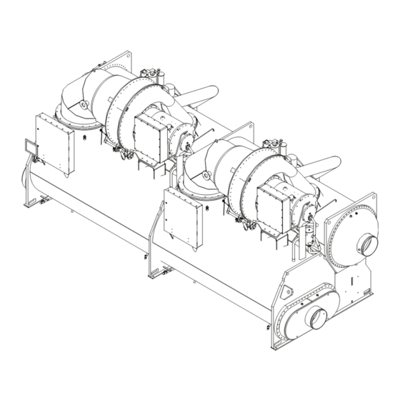
- Page 18 Dimensions and Weights Figure 3. Assembly for CDHF and CDHG CenTraVac chillers (CDHF shown) MAIN UNIT CONTROL PANEL OPTIONAL UNIT-MOUNTED Y2 (UATR, UPIR, & UXL STARTERS) REDUCED-VOLTAGE STARTERS Y3 (MOTOR TERMINAL BOX, NOT SHOWN) Y1 (USTR & USID STARTERS) COMPRESSOR CONTROL PANEL PURGE 1.0 (90D–1210A AFD)
- Page 19 Dimensions and Weights Figure 4. Assembly for CDHF and CDHG CenTraVac chillers (CDHF shown) OPTIONAL UNIT-MOUNTED MEDIUM (REDUCED) VOLTAGE MOTOR AUTOTRANSFORMER LARGEST MOTOR REMOVAL OR PRIMARY SPACE REACTOR STARTER ENCLOSURE IS 40.0 X 26.2 X 27.0 MAX. WEIGHT IS 1200 LB EACH MOTOR MOTOR ØT...
-
Page 20: Weights
Dimensions and Weights Weights Single Compressor and Duplex Chillers: Models CVHE, CVHF, CVHG CDHF, and CDHG Table 10. Compressor and motor weights Motor Weight Compressor and Motor Weight CPKW Model NTON Volts 190–270 6600 2558 1160 7294 3308 230–320 4160 2530 1147 7266... - Page 21 Dimensions and Weights Table 12. Evaporator and condenser bundle weights Evaporator Condenser Bundle Model Shell Size Shell Waterbox Shell Waterbox Size 032S 2778 1260 2458 1115 CVHE 032L 3483 1579 3006 1363 3526 050S 4897 2221 1061 1599 1328 4436 050L 5984 2714...
-
Page 22: Disassembly
The process is to be initiated by experienced service technicians. Contact your Pressure! local Trane Service office for assistance if required. Failure to follow instructions below could result in an This section discusses a typical disassembly process. -
Page 23: Purge Unit Removal
For variable frequency drives or other energy storing components provided by Trane or others, refer to the appropriate manufacturer’s literature for allowable waiting periods for discharge of capacitors. Verify with a CAT III or IV voltmeter rated per NFPA 70E that all capacitors have discharged. -
Page 24: Compressor Motor Assembly
If doweling is not factory installed, and it is necessary 1. Disconnect the inlet vane linkage. to install doweling, contact the local Trane Service a. Disconnect the rod end bearings connecting the Company. The compressor discharge flange and... - Page 25 Disassembly Figure 11. Vane actuator level on interstage Note: Cover all open connections to avoid prolonged exposure of oil to humid air. Remove oil if a chiller is kept in a disassembled condition for an extended time. Figure 13. Lubrication system supply, drain, and vent lines Figure 12.
- Page 26 Lifting cables (chains or slings) may not be of the same length. Adjust as necessary for even unit lift. 5. Only Trane Service Agencies have access to the certified lifting plates to allow safe compressor/motor assembly removal. Before removing the compressor/ motor assembly, consult with a rigging specialist.
-
Page 27: Compressor Motor Mount
Failure to follow instructions below could result in pins to locate the pieces properly. After the pieces are unit dropping which could result in death or serious located, Trane recommends welding the mount and injury, and equipment or property-only damage. backing plate in place. -
Page 28: Tracer Adaptiview Display Arm
11. Use the reverse order to reassemble the economizer on the chiller. Be sure to install new gaskets at the appropriate joints. 12. Torque all bolts to specifications. Consult with your Trane service group for specific torques for your economizer design. Tracer AdaptiView Display Arm Removal... -
Page 29: Control Panel Removal
For variable frequency drives or other energy storing components provided by Trane or others, refer to the appropriate manufacturer’s literature for allowable waiting periods for discharge of capacitors. Verify with a CAT III or IV voltmeter rated per NFPA 70E that all capacitors have discharged. -
Page 30: Condenser/Evaporator Disassembly
Lifting cables (chains or slings) or other energy storing components provided by may not be of the same length. Adjust as necessary Trane or others, refer to the appropriate for even unit lift. manufacturer’s literature for allowable waiting periods NOTICE for discharge of capacitors. -
Page 31: Disassembly Of Chillers With Options
Disassembly (see Figure 22, p. 31). Then remove the bolts from the WARNING flanges connecting the shells. Refrigerant May Be Under Positive Note: Some small shell combinations do not have Pressure! flanged connections between shells. Failure to follow instructions below could result in an 4. - Page 32 Disassembly 2. Remove the bolts from the flanges. 5. Torque all bolts to torque specifications listed in Table 14, p. 3. Lift the piping clear of the unit. 4. Reassemble the piping in the reverse order. Install new gaskets at the appropriate joints. CVHE-SVN04R-EN...
-
Page 33: Reassembly
This is the only to CTV-SB-66F (General Service Bulletin: CenTraVac sealing compound recommended by Trane for use on O-Ring and Flange Sealant), or the most recent O-ring joints. To use this sealing compound, apply a version. -
Page 34: Brazing
After the chiller has been moved to the equipment room and reassembled under Trane supervision, leak testing, and evacuation can be performed by Trane or under Trane supervision. Upon verification of leak tightness, installation can proceed for unit piping, wiring, etc. After installation has been completed, fill out CenTraVac™... - Page 35 Notes CVHE-SVN04R-EN...
- Page 36 For more information, please visit trane.com or tranetechnologies.com. Trane has a policy of continuous product and product data improvements and reserves the right to change design and specifications without notice. We are committed to using environmentally conscious print practices.
Need help?
Do you have a question about the CenTraVac CDHG Series and is the answer not in the manual?
Questions and answers