Table of Contents
Advertisement
Quick Links
IMPORTANT SAFEGUARDS. READ AND FOLLOW ALL SAFETY INSTRUCTIONS.
SAVE THESE INSTRUCTIONS.
All servicing should be performed by qualified personnel. When using electrical equipment, basic safety precautions should always
be followed including the following: (1) Do not use outdoors. (2) Do not use this equipment for other than its intended use. (3) Before
installing this fixture or doing any maintenance, make sure to turn off the power supply at the circuit breaker or fuse box. (4) Do not
handle energized module with wet hands or when standing on wet or damp surfaces, or in water. WARNING - Risk of Electric Shock.
Access above ceiling required. Do not install insulation within 3" (76mm) of any part of the luminaire. Suitable for suspended ceil-
ings. Maximum mounting height of 10 feet. The CR Series of recessed troffers is for non-insulated ceiling applications using T-Bar
ceiling grid only. Designed for use in 120-277V 50-60 Hertz protected circuit (fuse box, circuit breaker). Supply wire sized as per NEC
or governing code(s), 90C rated.
INSTALLATION INSTRUCTIONS:
TOP VIEW
1
Battery Pack
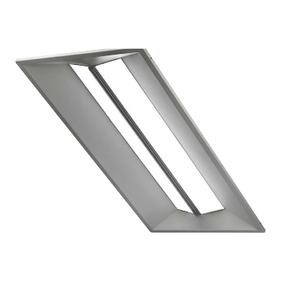
Luminaire
Battery Pack
2
a
Position
Power
Output
S1
S2
LINE
100%
On
On
50%
On
O
50%
O
On
0%
O
O
NOTE: (1) DO NOT CONNECT two separate phases of the line voltage to the
input of the CR Series LED Light Engines, the LED driver will be damaged and
not covered by warranty. (2) Install in accordance with National & Local Electric
Code(s). (3) The AC line inputs must be connected to the same phase of the line
voltage. (4) If step dimming isn't required, combine BLACK– Switched HOT #1
(S1) and BLACK– Switched HOT #2 (S2) together.
HOOK ON TO END CAP
STEP DIMMING
DRIVER ASSEMBLY
BLACK
S1
BLACK
S2
NEUTRAL
WHITE
RED
UNSWITCHED HOT
Step 1:
Unpack the CR Troffer, light engine and remote kit from its shipping
container.
Step 2: (Figure 1 & Figure 2)
Hang battery pack at one end of the troffer, opposite of the driver
enclosure.
Step 3: (Figure 3)
Run wire harness to PCB along side of troffer.
Step 4:
Attach battery side of wire harness to the battery connector located
on top of the driver enclosure.
Step 5:
Connect wire harness to driver as shown in wiring diagram below:
For Step Dimming see Figure a, for 0-10V Dimming see Figure b.
Step 6:
Complete installation with SMK instructions.
RUN WIRE HARNESS
DOWN TO PCB
ALONG SIDE
3
b
LINE S1
UNSWITCHED HOT
EB14SMK
Including : CR24-EB14, CR14-EB14, CR22-EB14, CR-LE-EB14
Battery Pack
0-10V DIMMING
VIOLET
DRIVER ASSEMBLY
GREY
WHITE
BLACK
RED
Advertisement
Table of Contents

Subscribe to Our Youtube Channel
Related Manuals for Cree EB14SMK


Summary of Contents for Cree EB14SMK
- Page 1 EB14SMK Including : CR24-EB14, CR14-EB14, CR22-EB14, CR-LE-EB14 IMPORTANT SAFEGUARDS. READ AND FOLLOW ALL SAFETY INSTRUCTIONS. SAVE THESE INSTRUCTIONS. All servicing should be performed by qualified personnel. When using electrical equipment, basic safety precautions should always be followed including the following: (1) Do not use outdoors. (2) Do not use this equipment for other than its intended use. (3) Before installing this fixture or doing any maintenance, make sure to turn off the power supply at the circuit breaker or fuse box.
- Page 2 For fault conditions described in this User Manual that persist and do not auto-clear, the user AC present, Test complete: Battery Test Passed = back to should contact a Cree Authorized representative for information regarding product services battery charge in progress state and/or returns.
Need help?
Do you have a question about the EB14SMK and is the answer not in the manual?
Questions and answers