Advertisement
Quick Links
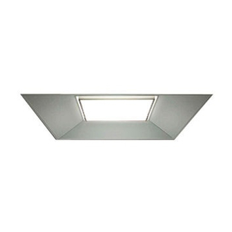
The LR24
architectural LED tro er is for non-insulated
TM
ceiling applications using 2' x 2' t-bar ceiling grid only.
Designed for use in 120V~277V, 50-60 Hertz protected circuit
(fuse box, circuit breakers) and supply wire (18AWG, stranded,
600V, 90°C rated). SELV equivalent control gear.
!
CAUTION: Risk of Electric Shock
Dry location use only. Access above ceiling required. Do
not install insulation within 76 mm (3 in) of any part of the
luminaire. Suitable for suspended ceilings.
IMPORTANT SAFETY INFORMATION
Maximum case temperature is 51c at 25c ambient.
Read all instructions before installation.
Before installing this fixture or doing any maintenance, make sure
to turn o the power supply at the circuit breaker or fuse box.
Check to make sure that all fixture connections have been
properly made and the fixture is grounded to avoid potential
electrical shocks.
Do not handle energized fixture when hands are wet, when
standing on wet or damp surfaces, or in water.
TO INSTALL:
STEP 1:
Carefully unpack the LR24 from its' shipping containers. In-
spect product for defects due to shipping.
STEP 2:
Place the LR24 into the 2' x 2' T bar ceiling panel
(see figure 1). Assembly should fit tight and not need fasteners.
STEP 3:
Make sure that the orientation of the sheet metal assembly
junction box (see "B" on Figure 1) faces an accessible panel to
install the input power.
STEP 4:
Remove junction box door (see "A" on Figure 2).
STEP 5:
Using a screwdriver blade, remove appropriate knockout from
junction box door to route input conduit.
FIGURE 1
STEP 6:
Connect wires as shown in wiring diagram (Figure 3). Push all
wires back into the junction box.
STEP 7:
Replace junction box door and tighten screw to secure.
CONNECTING/DISCONNECTING POWER TO LR24
STEP 8:
To connect power to the light engine, align the GU24 connector
whip "E"(see Fig 4) with the GU24 pins "F" on the light engine.
STEP 9:
Push the connector completely over the pins and rotate the
whip clockwise until locked (see Fig 5).
LR24
INSTALLATION INSTRUCTIONS
FIGURE 2
TM
Advertisement

Related Manuals for Cree LR24 Series


Summary of Contents for Cree LR24 Series
- Page 1 LR24 INSTALLATION INSTRUCTIONS The LR24 architectural LED tro er is for non-insulated ceiling applications using 2’ x 2’ t-bar ceiling grid only. Designed for use in 120V~277V, 50-60 Hertz protected circuit (fuse box, circuit breakers) and supply wire (18AWG, stranded, 600V, 90°C rated).
- Page 2 ® The limited warranty set forth below is given by the Cree company listed below (“Seller”) with respect to the lighting product packaged with this limited warranty (the “Product”). Your Product, when delivered to you in new condition in its original packaging, is warranted against defects in materials or workmanship as follows: for a period of FIVE (5) YEARS from the date of original purchase, defective parts or a defective Product returned with the sales receipt as proof of purchase to Seller, or its authorized service providers, as applicable, and proven to be defective upon inspection, will be repaired, or exchanged for a new Product, as determined by Seller, or the authorized service provider.
Need help?
Do you have a question about the LR24 Series and is the answer not in the manual?
Questions and answers