Advertisement
Quick Links
IMPORTANT SAFEGUARDS
WARNING
circuit breaker before installing or servicing.
READ AND FOLLOW ALL SAFETY
INSTRUCTIONS
1.
WARNING
requires knowledge of luminaires electrical systems. If not qua
2.
WARNING – To prevent wiring damage or abrasion, do not expose
wiring to edges of sheet metal or other sharp objects.
3.
WARNING
luminaires that have the construction features and dimensions
shown in the photographs and/or drawings
the retrofit kit does not exceed the input rating of the luminaire.
4.
SUITABLE FOR TYPE IC LUMINAIRES.
5.
It may be necessary to remove a socket mounting plate for adequate
clearance.
6.
Each lampholder shall be installed only in its intended manner and
orientation.
7.
Suitable for Wet Locations.
8.
Min. temperature rating of -25°C.
9.
Do
not make or alter any open holes in an enclosure of wiring or
electrical components during kit installation.
10.
SUITABLE FOR INSTALLATION IN A RECESSED CAN WITH
A MAXIMUM OF EIGHT (8) No. 12 AWG THROUGH-BRANCH
CIRCUIT CONDUCTORS SUITABLE FOR 75°C MIN.
11.
WARNING-THIS RETROFIT KIT IS ACCEPTED AS A COMPONENT
OF A LUMINAIRE WHERE THE SUITABILITY OF THE COMBINATION
SHALL BE DETERMINED BY AUTHORITIES HAVING JURISDICTION.
MIN. LAMP COMPARTMENT DIMENSIONS
5.5 inch/139.7mm (DIA) x 5.5 inch/139.7mm (H).
12.
This device is not intended for use with emergency exit fixtures or
emergency exit lights.
SAVE THESE INSTRUCTIONS FOR
FUTURE REFERENCE
TO INSTALL:
2
Flip Clip
STEP 1:
Carefully rotate the"Flip Clips"clockwise
until the clips are fully-dep loyed. See
Figure 2.
1 of 2
where the input rating of
3
B
A
NOTE: For 5" recessed cans, it is
recommended not to rotate the flip clips
into the ful ly dep loyed position.
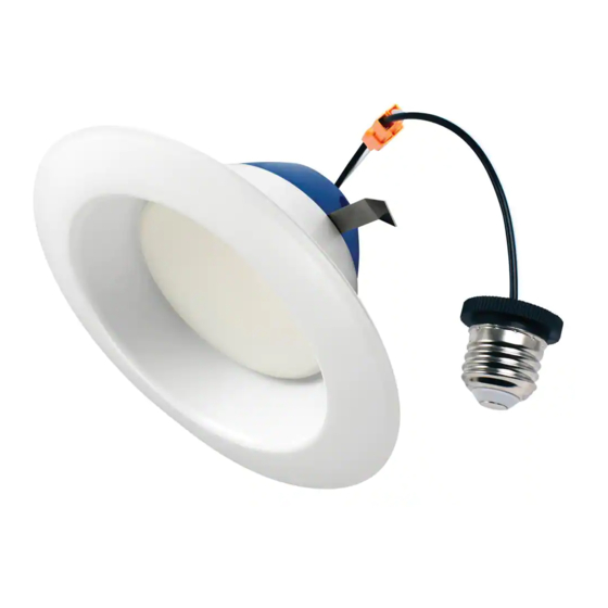
6" Recessed LED Downlight
Package Contents:
Part
Description
A
6" Retrofit downlight
B
Edison Socket Adapter
C
Field applied label
1
Minimum distance
bet ween edge of
fixtu re and top of
housing or other
ob struction.
7.48 inch
(190mm)
RECESSED HOUSING COMPATIBILITY
•
Designed to install in standard 6in recessed downlight
housings.
•
Compatible with most dimmers when used with multiple
fixtures. Consult ww w.creebulb.com/dimmers for a
compatibility chart.
•
Compatibility of housings may be determined by
measurement of the housing as detailed in the drawing
above (Figure 1).
STEP 2:
Make sure the POWER IS TURNED OFF at
the source to the recessed can.
STEP 3:
Remove existing trim and bulb, revealing
the existing recessed socket.
STEP 4:
Install "Field Applied Label" into the
recessed can.
STEP 5:
Screw the fixtu re Edison base assembly
into the recessed can socket by turni ng
clockwise. See Figure 3.
STEP 6:
Install fixture up in to the recessed housing
firmly until trim ring is flush with the
ceiling. Rotate fixtu re clockwise slight ly to
tigh ten fit with ceiling and set in recessed
h
o
u
s
n i
. g
F
l C
p i
" s
a
e r
n
clips inside of recessed housing during
installation. See Figure 3 and 4.
TRDL6 Series
Quantity
1
1
1
5.5 inch
(139.7mm)
5.5 inch
(139.7mm)
r o
b
e
s
r t
s e
l u
s t
e ,
n
s
r u
" e
l F
p i
t o
l a
g i
n
e
d
i w
h t
m
e
t
l a
i r t
m
LPN000241 REV B
Advertisement

Related Manuals for Cree TRDL6 Series


Summary of Contents for Cree TRDL6 Series
- Page 1 TRDL6 Series 6” Recessed LED Downlight IMPORTANT SAFEGUARDS WARNING Package Contents: circuit breaker before installing or servicing. Part Description Quantity READ AND FOLLOW ALL SAFETY 6” Retrofit downlight INSTRUCTIONS Edison Socket Adapter WARNING Field applied label requires knowledge of luminaires electrical systems. If not qua WARNING –...
- Page 2 © 2016 Cree, Inc. All rights reserved. For informational purposes on ly. Content is subject to change. See ww w.creebulb. com/warranty for warranty and specifi cations. Cree is a registered trademark, and the C ree logo is a trademark of Cree, Inc.
Need help?
Do you have a question about the TRDL6 Series and is the answer not in the manual?
Questions and answers