Advertisement
IMPORTANT SAFEGUARDS
When using electrical equipment, basic safety precautions should always be
followed including the following:
READ AND FOLLOW ALL SAFETY INSTRUCTIONS
1.
To reduce the risk of electrical shock, turn off power supply before
installation or servicing.
2.
This luminaire must be installed in accordance with the NEC or your local
electrical code. If you are not familiar with these codes and requirements,
consult a qualified electrician.
3.
Check to make sure that all input power connections have been properly
made and the module is grounded to avoid potential electrical shock.
4.
DO NOT lift luminaire by the power leads or cord.
5.
Suitable for dry and damp location
6.
Suitable for locations with maximum ambient of 50°C
7.
MIN 90°C SUPPLY CONDUCTORS
SAVE THESE INSTRUCTIONS FOR FUTURE REFERENCE
NOTE:
•
For each mounting application below, when mounting to surface ensure
that the mounting surface and customer supplied hardware is capable of
supporting the weight of the luminaire.
•
Luminaires with a single driver box, the center of mounting is NOT the
same as the center of luminaire.
TO INSTALL:
JUNCTION BOX MOUNT / PENDANT MOUNT
STEP 1:
Remove hinged splice box cover from
top of housing by loosening set screw
and sliding box to the right and up from
"L" channel. Unhook from hinge holes.
See Figure 1.
STEP 2:
Attach hinged splice box cover
to customer supplied pendant or
mounting surface.
For pendant entering the hinge box:
Use 3/4" threaded pendant, along with
two locknuts (one for inside the splice
box and one for outside the splice box).
Pull supply leads into position from
customer supplied conduit.
Note: The luminaire should already
be factory set for correct balance.
1 of 2
1
Pendant
Adjustment
3/4" ( 19mm )
Knockouts
"L" Channel
However, should you need to, the
luminaire may be balanced by
loosening (2) set screws for pendant
adjustment on the top of the hinged
splice box and sliding the adjustment
plate as necessary for correct balance.
Tighten (2) set screws when finished.
See Figure 1.
For junction box mounting the hinge
box:
Use designated mounting holes on top
of hinge splice box. See Figure 1. For
conduit entering the hinge splice box
from the side, use appropriately-sized
threaded conduit (1/2" or 3/4"), and
conduit fitting.
STEP 3:
Attach one end of the hinged splice
Junction Box, Pendant and Hook and Cord
INSTALLATION INSTRUCTIONS
Holes for Surface Mounting
and Splice Box Mounting
3/4" ( 19mm )
Pendant Mount Hole
1/2" ( 13mm )
Knockouts
box to luminaire by aligning hinge
slots on Mounting Bracket with hinges
(on splice box), and then inserting the
hinges into the slots.
STEP 4:
Make wire connections per Electrical
Connection section and then push the
leads into hinged splice box.
STEP 5:
Secure other end of the hinged splice
box to luminaire by sliding screw on
Mounting Bracket up and over in "L"
channel on the hinged splice box. See
Figure 1.
STEP 6:
Secure luminaire to hinged splice box
by tightening screw.
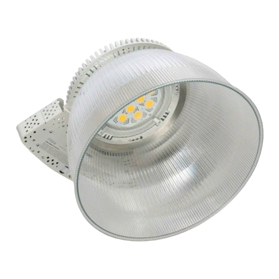
CXB Series
LED Luminaire
LPN000190_B
Advertisement
Table of Contents

Related Manuals for Cree CXB Series


Summary of Contents for Cree CXB Series
- Page 1 CXB Series LED Luminaire Junction Box, Pendant and Hook and Cord IMPORTANT SAFEGUARDS INSTALLATION INSTRUCTIONS When using electrical equipment, basic safety precautions should always be followed including the following: READ AND FOLLOW ALL SAFETY INSTRUCTIONS To reduce the risk of electrical shock, turn off power supply before installation or servicing.
- Page 2 NEUTRAL NEUTRAL-WHITE green wire position of the terminal block. © 2013 Cree, Inc. All rights reserved. For informational purposes only. Content is subject to change. See www.cree.com/lighting/products/warranty for warranty and specifications. Cree® and the Cree logo are registered trademarks. www.cree.com/lighting...
Need help?
Do you have a question about the CXB Series and is the answer not in the manual?
Questions and answers