Table of Contents
Advertisement
Quick Links
Advertisement
Table of Contents

Subscribe to Our Youtube Channel
Related Manuals for SICK LBR


Summary of Contents for SICK LBR
- Page 1 OPERATING INSTRUCTIONS Two-wire 4 … 20 mA/HART...
-
Page 2: Table Of Contents
Setup with PACTware ......................50 Connect the PC ......................50 Parameter adjustment ....................50 Saving the parameterisation data ................... 50 Diagnosis, asset management and service ................ 51 Maintenance ........................51 Measured value and event memory ................51 LBR • Two-wire 4 … 20 mA/HART... - Page 3 10.3 Dimensions ........................71 10.4 Trademark ........................81 Safety instructions for Ex areas Take note of the Ex specific safety instructions for Ex applications. These instructions are attached as documents to each instrument with Ex approval and are part of the operating instructions. Editing status: 2020-04-21 LBR • Two-wire 4 … 20 mA/HART...
-
Page 4: About This Document
The dot set in front indicates a list with no implied sequence. Sequence of actions Numbers set in front indicate successive steps in a procedure. Battery disposal This symbol indicates special information about the disposal of bat- teries and accumulators. LBR • Two-wire 4 … 20 mA/HART... -
Page 5: For Your Safety
During work on and with the device, the required personal protective equipment must always be worn. Appropriate use LBR is a sensor for continuous level measurement. You can find detailed information about the area of application in chapter "Product description". Operational reliability is ensured only if the instrument is properly used according to the specifications in the operating instructions manual as well as possible supplementary instructions. -
Page 6: Eu Conformity
When installed within 4 to 40 km of a radio astronomy station, the instrument must not be mounted higher than 15 m above the ground. A list of the respective radio astronomy stations can be found in chap- ter "Appendix" of the operating instructions. LBR • Two-wire 4 … 20 mA/HART... -
Page 7: Radio License For Usa
This device is limited to installation in a completely enclosed container made of metal or concrete to prevent RF emissions, which can otherwise interfere with aeronautical navigation, the maximum approved tilt angel is 10°. From electronics index .-03 the use in containers made of reinforced fiberglass is also permit- ted. LBR • Two-wire 4 … 20 mA/HART... - Page 8 L'angle d'inclinaison maximum autorisé est de 10°. De l'indice électronique .-03, l'utilisation dans des conteneurs fabriqués en fibre de verre est également permise. • Environnement ouvert : Pour l'utilisation hors des cuves fermées, la condition suivante doit être remplie : L'appareil doit être installé LBR • Two-wire 4 … 20 mA/HART...
-
Page 9: Installation And Operation In The Usa And Canada
USA and Canada. 2.11 Safety instructions for Ex areas For Ex applications, only devices with corresponding Ex approval may be used. Observe the Ex-specific safety instructions. These are an integral part of the operating instructions and are enclosed with every device with Ex approval. LBR • Two-wire 4 … 20 mA/HART... -
Page 10: Product Description
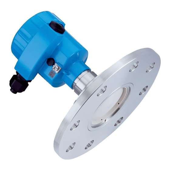
Principle of operation Application area The LBR is a radar sensor for continuous level measurement of bulk solids under different process conditions. It is ideal for level measurement in very high silos, large bunkers and segmented vessels. The very good signal focussing ensures a simple setup and reliable measurement. -
Page 11: Packaging, Transport And Storage
Display and adjustment The display and adjustment module is used for measured value indi- module cation, adjustment and diagnosis. The integrated Bluetooth module (optional) enables wireless adjust- ment via standard adjustment devices. LBR • Two-wire 4 … 20 mA/HART... - Page 12 3 Product description The electronics module LBR is a replacement part for radar sensors Electronics module LBR. LBR • Two-wire 4 … 20 mA/HART...
-
Page 13: Mounting
USA" "Radio approval for Canada" of this operating instructions. Mounting versions, plastic horn antenna Mounting strap The optional mounting strap allows simple mounting of the instrument on a wall, ceiling or boom. Especially in the case of open vessels, this LBR • Two-wire 4 … 20 mA/HART... - Page 14 Fig. 2: Ceiling mounting via the mounting strap with length 300 mm Mounting strap - Wall As an alternative the strap mounting is carried out horizontally or mounting obliquely. > 200 mm (7.87") Fig. 3: Wall mounting horizontally via the mounting strap with length 170 mm LBR • Two-wire 4 … 20 mA/HART...
- Page 15 DN 80, ASME 3" and JIS 80. It comes not sealed against the radar sensor and can thus only be used unpressurized. It can be retrofitted on instruments with single chamber housing, retrofitting to a double chamber housing is not possible. Fig. 5: Combi compression flange Combi compression flange Adapter flange The adapter flange is available from DN 100, ASME 4" and JIS 100. It is permanently connected with the radar sensor and sealed. LBR • Two-wire 4 … 20 mA/HART...
-
Page 16: Mounting Preparations, Mounting Strap
• Single chamber housing – Angle of inclination in three steps 0°, 90° and 180° – Angle of inclination 180°, infinitely variable • Double chamber housing – Angle of inclination in two steps 0° and 90° – Angle of inclination 90°, infinitely variable LBR • Two-wire 4 … 20 mA/HART... -
Page 17: Mounting Instructions
Nose for marking the direction of polarisation Note: When the housing is rotated, the direction of polarization changes and hence the influence of the false echo on the measured value. Please keep this in mind when mounting or making changes later. Installation position Mount the sensor at least 200 mm (7.874 in) away from the vessel wall. LBR • Two-wire 4 … 20 mA/HART... - Page 18 Silo with filling from top The optimal mounting position is opposite the filling aperture. To avoid heavy soiling, the distance to any filter or dust exhauster should be as large as possible. Fig. 12: Mounting of the radar sensor with inflowing medium Silo with lateral filling In bulk solids silos with lateral pneumatic filling the instrument should not be mounted above the filling stream, as the radar signal will be disrupted. The optimal mounting position is to the side of the filling aperture. To avoid heavy soiling, the distance to any filter or dust exhauster should be as large as possible. LBR • Two-wire 4 … 20 mA/HART...
- Page 19 With threaded connection, the antenna end should protrude at least 5 mm (0.2 in) out of the socket. Fig. 14: Recommended socket mounting with different versions of LBR Metal-jacketed lens antenna Plastic horn antenna Thread with integrated horn antenna...
- Page 20 4 Mounting If the reflective properties of the medium are good, you can mount LBR on sockets longer than the antenna. The socket end should be smooth and burr-free, if possible also rounded. Note: When mounting on longer sockets, we recommend carrying out a false signal suppression (see chapter "Parameter adjustment").
- Page 21 Alternatively, the angle of inclination can be determined using the following drawing and table. It depends on the measuring distance "d" and the distance "a" between vessel centre and mounting position. Check the alignment with a suitable level or water level. LBR • Two-wire 4 … 20 mA/HART...
- Page 22 4 Mounting Fig. 17: Determination of the angle of inclination for alignment of LBR Distance d 2° 4° 6° 8° 10° 10.5 12.2 11.1 13.9 12.5 15.6 LBR • Two-wire 4 … 20 mA/HART...
- Page 23 In case of existing vessel installations, a false signal suppression should be carried out during setup. If large vessel installations such as struts or supports cause false echoes, these can be attenuated through supplementary measures. Small, inclined sheet metal baffles above the installations "scatter" the radar signals and prevent direct interfering reflections. LBR • Two-wire 4 … 20 mA/HART...
- Page 24 Information: The spacer may only be incorporated up to a maximum of 50 mm into the vessel insulation. Only then is a reliable temperature decoupling guaranteed. LBR • Two-wire 4 … 20 mA/HART...
- Page 25 The best mounting location is on the outer wall of the silo, with the sensor pointing towards the discharge opening in the silo centre. This can be accomplished, for example, with the mounting strap. Fig. 22: Installation and orientation in multiple chamber silos LBR • Two-wire 4 … 20 mA/HART...
- Page 26 Fig. 24: Rinsing air connection on metal-jacketed lens antenna Plastic horn antenna The LBR with plastic horn antenna is optionally available with a rins- ing air connection. The mechanical configuration differs according to the flange version, see following graphics. LBR • Two-wire 4 … 20 mA/HART...
- Page 27 4 Mounting Fig. 25: Rinsing air connection with compression flange Fig. 26: Rinsing air connection with adapter flange You can find details on the rinsing air connection in chapter "Technical data". LBR • Two-wire 4 … 20 mA/HART...
-
Page 28: Connecting To Power Supply
In the case of instrument housings with self-sealing NPT threads, it is not possible to have the cable entries screwed in at the factory. The free openings for the cable glands are therefore covered with red dust protection caps as transport protection. LBR • Two-wire 4 … 20 mA/HART... -
Page 29: Connecting
4. Remove approx. 10 cm (4 in) of the cable mantle, strip approx. 1 cm (0.4 in) of insulation from the ends of the individual wires 5. Insert the cable into the sensor through the cable entry LBR • Two-wire 4 … 20 mA/HART... -
Page 30: Wiring Plan, Single Chamber Housing
10. Reinsert the display and adjustment module, if one was installed 11. Screw the housing lid back on The electrical connection is finished. Wiring plan, single chamber housing The following illustration applies to the non-Ex as well as to the Ex-ia version. LBR • Two-wire 4 … 20 mA/HART... -
Page 31: Switch-On Phase
PC • The output signal jumps briefly to the set fault current Then the actual measured value is output to the signal cable. The value takes into account settings that have already been carried out, e.g. default setting. LBR • Two-wire 4 … 20 mA/HART... -
Page 32: Set Up With The Display And Adjustment Module
Fig. 29: Insertion of the display and adjustment module with single chamber housing Note: If you intend to retrofit the instrument with a display and adjustment module for continuous measured value indication, a higher lid with an inspection glass is required. LBR • Two-wire 4 … 20 mA/HART... -
Page 33: Adjustment System
The pen oper- ates the four keys of the display and adjustment module right through the closed lid (with inspection window) of the sensor housing. LBR • Two-wire 4 … 20 mA/HART... -
Page 34: Measured Value Indication - Selection Of National Language
Selection of national This menu item is used to select the national language for further pa- language rameter adjustment. You can change the selection via the menu item "Setup - Display, Menu language". LBR • Two-wire 4 … 20 mA/HART... -
Page 35: Parameter Adjustment - Quick Setup
In the main menu item "Setup", the individual submenu items should be selected one after the other and provided with the correct parameters to ensure optimum adjustment of the measurement. The procedure is described in the following. LBR • Two-wire 4 … 20 mA/HART... - Page 36 Depending on the type of bulk solids application, material cones and additional echoes from the vessel wall or bottom can become further interfering factors. Through this selection, the sensor is adapted perfectly to the application. LBR • Two-wire 4 … 20 mA/HART...
- Page 37 6 Set up with the display and adjustment module Vessel height/Measuring range: The LBR is a bulk solids radar sensor for high, slender vessels. It covers a measuring range up to 120 m. This menu item lets you limit the active measuring range in which the instrument searches for level echoes.
- Page 38 To perform the adjustment, enter the distance with full and empty ves- sel, see the following example: LBR • Two-wire 4 … 20 mA/HART...
- Page 39 2. Prepare the percentage value for editing with [OK] and set the cursor to the requested position with [->]. 3. Set the requested percentage value with [+] and save with [OK]. The cursor jumps now to the distance value. LBR • Two-wire 4 … 20 mA/HART...
- Page 40 In the menu item "Current output mode" you determine the output mode characteristics and reaction of the current output in case of fault. The default setting is output characteristics 4 … 20 mA, fault mode < 3.6 mA. LBR • Two-wire 4 … 20 mA/HART...
- Page 41 • Chinese • Polish • Czech • Turkish In the delivery status, the LBR is set to the ordered national language. Display - Displayed value In this menu item you can define the way measured values are indi- 1 and 2 cated on the display. LBR • Two-wire 4 … 20 mA/HART...
- Page 42 The signal strength enables an evaluation of the quality of the measurement. The selected curve is continuously updated. A submenu with zoom functions is opened with the [OK] key: • "X-Zoom": Zoom function for the meas. distance • "Y-Zoom": 1, 2, 5 and 10x signal magnification in "dB" LBR • Two-wire 4 … 20 mA/HART...
- Page 43 With the adjustment software PACTware and the PC, the stored echo curves can be displayed with high resolution and used to recognize signal changes over time. In addition, the echo curve saved during setup can also be displayed in the echo curve window and compared with the current echo curve. LBR • Two-wire 4 … 20 mA/HART...
- Page 44 The event and parameter modification memories remain unaffected. Basic settings: Resets the parameter settings, incl. special param- eters, to the default values of the respective instrument. Any stored false signal suppression or user programmable linearisation curve, as LBR • Two-wire 4 … 20 mA/HART...
- Page 45 Additional settings - Copy The instrument settings are copied with this function. The following instrument settings functions are available: • Read from sensor: Read data from sensor and store into the display and adjustment module LBR • Two-wire 4 … 20 mA/HART...
- Page 46 (size) variable the current output refers to. Additional settings - Cur- In menu item "Current output, adjustment" you can assign a respec- rent output (adjustment) tive measured value to the current output. LBR • Two-wire 4 … 20 mA/HART...
- Page 47 This is useful if the saved false signal suppression no longer matches the metrological conditions in the vessel. Extend: is used to extend an already created false signal suppres- sion. This is useful if a false signal suppression was carried out with LBR • Two-wire 4 … 20 mA/HART...
- Page 48 • Instrument name and serial number • Hardware and software version • Date of the factory calibration as well as the last change via adjust- ment instruments • Sensor characteristics such as approval, process fitting, seal, meas. range etc. LBR • Two-wire 4 … 20 mA/HART...
-
Page 49: Saving The Parameterisation Data
In the display and adjust- If the instrument is equipped with a display and adjustment module, ment module the parameter adjustment data can be saved therein. The procedure is described in menu item "Copy device settings". LBR • Two-wire 4 … 20 mA/HART... -
Page 50: Setup With Pactware
The latest DTM Collection and PACTware version can be downloaded free of charge via the Internet. Saving the parameterisation data We recommend documenting or saving the parameterisation data via PACTware. That way the data are available for multiple use or service purposes. LBR • Two-wire 4 … 20 mA/HART... -
Page 51: Diagnosis, Asset Management And Service
(non-deletable). Each entry contains date/time, event type, event description and value. Event types are for example: • Modification of a parameter • Switch-on and switch-off times • Status messages (according to NE 107) • Error messages (according to NE 107) LBR • Two-wire 4 … 20 mA/HART... -
Page 52: Asset Management Function
This status message is always active. It cannot be deactivated by the user. Function check: The instrument is being worked on, the measured value is temporarily invalid (for example during simulation). This status message is inactive by default. LBR • Two-wire 4 … 20 mA/HART... - Page 53 Error in the calibration carried out Exchanging the electronics Byte 4, Bit 0 of in the factory Byte 0 … 5 Error in the cali- Send instrument for repair bration Error in the EEPROM LBR • Two-wire 4 … 20 mA/HART...
- Page 54 Error in the non- Send instrument for repair active linearisation table M502 Hardware error EEPROM Exchanging the electronics Byte 24, Bit 2 of Byte 14 … 24 Error in the event Send instrument for repair memory LBR • Two-wire 4 … 20 mA/HART...
-
Page 55: Rectify Faults
The following table describes possible errors in the current signal and helps to eliminate them: Error Cause Rectification 4 … 20 mA signal not stable Fluctuating measured value Set damping LBR • Two-wire 4 … 20 mA/HART... - Page 56 Amplitude or position of a false signal has Determine the reason for the changed false changed (e.g. condensation, buildup); false signals, carry out false signal suppression, signal suppression no longer matches ac- e.g. with condensation time tual conditions LBR • Two-wire 4 … 20 mA/HART...
- Page 57 Carry out false signal suppression or in- jumps sporadically on the antenna crease false signal suppression in the close towards 100 % dur- range by editing. ing emptying With bulk solids use radar sensor with purg- ing air connection or flexible antenna cover. time LBR • Two-wire 4 … 20 mA/HART...
-
Page 58: Exchanging The Electronics Module
A fresh setup is then not necessary. How to proceed if a repair is necessary If a repair should be necessary, please contact your contact person. LBR • Two-wire 4 … 20 mA/HART... -
Page 59: Dismount
Pass the instrument directly on to a specialised recycling company and do not use the municipal collecting points. If you have no way to dispose of the old instrument properly, please contact us concerning return and disposal. LBR • Two-wire 4 … 20 mA/HART... -
Page 60: Supplement
Ʋ Compression flange PP-GF30 black Ʋ Mounting strap 316L Ʋ Fixing screws, mounting strap 316L Ʋ Fixing screws, adapter flange Ʋ Plastic housing Plastic PBT (Polyester) Housing Ʋ Aluminium die-cast housing Aluminium die-casting AlSi10Mg, powder-coated (Basis: Polyester) LBR • Two-wire 4 … 20 mA/HART... - Page 61 The measured quantity is the distance between the end of the sensor antenna and the product surface. The reference plane for the measurement is the lower side of the flange. Glass with Aluminium and stainless steel precision casting housing LBR • Two-wire 4 … 20 mA/HART...
- Page 62 Further information on Manufacturer ID, See website of HART Communication Foundation Device ID, Device Revision Output variable - Additional current output Output signal 4 … 20 mA Default values can be assigned individually. LBR • Two-wire 4 … 20 mA/HART...
- Page 63 - 5 mm (- 0.197 in) - 30 mm (- 1.181 in) Fig. 36: Deviation under reference conditions Reference plane Recommended min. distance, specifications see below Measuring range end Already included in the meas. deviation LBR • Two-wire 4 … 20 mA/HART...
- Page 64 Process conditions For the process conditions, please also note the specifications on the type label. The lowest value always applies. Process temperature Depending of the reflective properties of the measured media. Time span (after a sudden measuring distance change of max. 2 m in bulk solids applications) until the output signal has taken on 90 % of the final value for the first time (IEC 61298-2). Outside the specified beam angle, the energy level of the radar signal is 50% (-3 dB) less. EIRP: Equivalent Isotropic Radiated Power LBR • Two-wire 4 … 20 mA/HART...
- Page 65 -40°C / -40°F Fig. 37: Derating, ambient temperature, metal-jacketed lens antenna up to +130 °C (+266 °F) Ambient temperature Process temperature Aluminium housing Plastic housing Stainless steel housing (precision casting) Stainless steel housing (electropolished) LBR • Two-wire 4 … 20 mA/HART...
- Page 66 Stainless steel housing (electropolished) 80 °C (176 °F) 0 °C (32 °F) 80 °C -40 °C (176 °F) (-104 °F) -40 °C (-104 °F) Fig. 39: Derating, ambient temperature, plastic horn antenna Ambient temperature Process temperature LBR • Two-wire 4 … 20 mA/HART...
- Page 67 Fig. 41: Derating, ambient temperature, thread G1½ with integrated horn antenna up to +200 °C (+392 °F) Ambient temperature Process temperature Aluminium housing Plastic housing Stainless steel housing (precision casting) Stainless steel housing (electropolished) LBR • Two-wire 4 … 20 mA/HART...
- Page 68 1.6 bar (23.2 psig) 4.3 m 1.8 bar (20.3 psig) 4.5 m 3.5 m 2 bar (23.2 psig) 4.6 m Plastic horn antenna Air volume Pressure Without reflux valve With reflux valve 0.2 bar (2.9 psig) 3.3 m LBR • Two-wire 4 … 20 mA/HART...
- Page 69 ● steel Wire cross-section (spring-loaded terminals) Ʋ Massive wire, stranded wire 0.2 … 2.5 mm² (AWG 24 … 14) Ʋ Stranded wire with end sleeve 0.2 … 1.5 mm² (AWG 24 … 16) LBR • Two-wire 4 … 20 mA/HART...
- Page 70 Stainless steel (electro-pol- Single chamber IP66/IP68 (0.2 bar) Type 6P ished) Stainless steel (precision Single chamber IP66/IP68 (0.2 bar) Type 6P casting) IP68 (1 bar) Galvanic separation between electronics and metal housing parts LBR • Two-wire 4 … 20 mA/HART...
-
Page 71: Radio Astronomy Stations
Protection rating (IEC 61010-1) 10.2 Radio astronomy stations Certain restrictions on the use of LBR outside closed vessels result from the radio license. You can find these restrictions in chapter "Radio license for Europe". Some of these restrictions have to do radio astronomy stations. The following table states the geographic positions of radio astronomy... - Page 72 G 1/8" x 8mm ø 98 mm (3.86") Fig. 45: LBR, metal-jacketed lens antenna (flange thickness acc. to drawing, flange dimensions acc. to DIN, ASME, JIS) Version up to 130 °C (266 °F) Version up to 200 °C (392 °F)
- Page 73 35 mm (1.38") 43 mm (1.69") 35 mm (1.38") Fig. 46: LBR, metal-jacketed lens antenna with rinsing connection Version up to 130 °C (266 °F) Version up to 200 °C (392 °F) Blind plug 90° angle joint Reflux valve LBR, metal-jacketed lens antenna with swivelling holder Fig.
- Page 74 10 Supplement LBR, metal-jacketed lens antenna with swivelling holder and rinsing connection Fig. 48: LBR, metal-jacketed lens antenna with swivelling holder and rinsing connection Version up to 130 °C (266 °F) Version up to 200 °C (392 °F) Blind plug 90°...
- Page 75 ø 75 mm (2.95") ø 115 mm (4.53") ø 156 mm (6.14") ø 200 mm (7.87") Fig. 49: LBR with compression flange suitable for flanges 3" 150 lbs, DN 80 PN 16 Compression flange LBR • Two-wire 4 … 20 mA/HART...
- Page 76 ø 156 mm (6.14") ø 200 mm (7.87") Fig. 50: LBR with compression flange suitable for flanges 3" 150 lbs, DN 80 PN 16 and rinsing connection Compression flange Reflux valve Rinsing connection LBR • Two-wire 4 … 20 mA/HART...
- Page 77 10 Supplement LBR, plastic horn antenna with adapter flange ø 75 mm (2.95") ø 98 mm (3.86") ø 180 mm (7.09") ø 220 mm (8.66") Fig. 51: LBR with adapter flange DN 100 PN 16 Adapter flange Process seal LBR • Two-wire 4 … 20 mA/HART...
- Page 78 ø 75 mm (2.95") ø 98 mm (3.86") ø 180 mm (7.09") ø 220 mm (8.66") Fig. 52: LBR, adapter flange DN 100 PN 16 and rinsing connection Rinsing air connection Reflux valve Adapter flange LBR • Two-wire 4 … 20 mA/HART...
- Page 79 (0.10") ø 75 mm 9 mm (2.95") (0.35") ø 107 mm (4.21") ø 115 mm (4.53") 12 mm (0.47") Fig. 53: LBR, plastic horn antenna, mounting strap in 170 or 300 mm length LBR • Two-wire 4 … 20 mA/HART...
- Page 80 10 Supplement LBR, thread with integrated horn antenna Fig. 54: LBR, thread with integrated horn antenna TC G1½ (DIN 3852-A) TD 1½ NPT (ASME B1.20.1) Version up to 130 °C (266 °F) Version up to 200 °C (392 °F) LBR • Two-wire 4 … 20 mA/HART...
-
Page 81: Trademark
10 Supplement 10.4 Trademark All the brands as well as trade and company names used are property of their lawful proprietor/ originator. LBR • Two-wire 4 … 20 mA/HART... - Page 82 Notes LBR • Two-wire 4 … 20 mA/HART...
- Page 83 Notes LBR • Two-wire 4 … 20 mA/HART...
- Page 84 E-Mail support@sick.jp Nederlands Phone +31 (0)30 229 25 44 E-Mail info@sick.nl Norge More representatives and Phone +47 67 81 50 00 agencies in all major industrial E-Mail auste ord@sick.no nations at www.sick.com SICK AG | Waldkirch | Germany | www.sick.com 62273-EN-200520...
Need help?
Do you have a question about the LBR and is the answer not in the manual?
Questions and answers