
Related Manuals for SICK LMS1 Series


Summary of Contents for SICK LMS1 Series
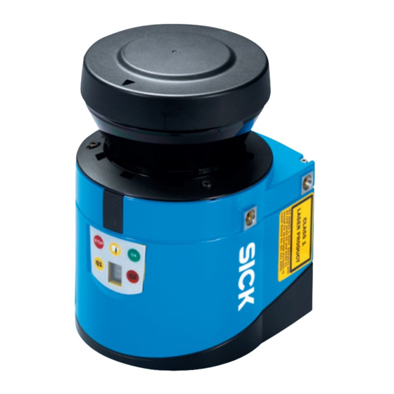
- Page 1 O P E R AT I N G I N S T R U C T I O N S Laser Measurement Sensors of the LMS1xx Product Family In full view in all weathers – compact and economical...
- Page 2 Reader™ is a trademark of Adobe Systems Incorporated. Version of the operating instructions The latest version of these operating instructions can be obtained as PDF at www.sick.com. 8012471/UT27/2012-02-14 © SICK AG · Germany · All rights reserved · Subject to change without notice...
-
Page 3: Table Of Contents
In the event of faults or errors .................. 80 Error displays of the LEDs ..................80 Indications of the 7-segment display ............... 81 Detailed error analysis ....................81 8012471/UT27/2012-02-14 © SICK AG · Germany · All rights reserved · Subject to change without notice... - Page 4 10.1 Overview of the annexes ..................92 10.2 Ordering information ....................92 10.3 Glossary ........................93 10.4 Illustration containing the EU declaration of conformity ........94 8012471/UT27/2012-02-14 © SICK AG · Germany · All rights reserved · Subject to change without notice...
- Page 5 Gesamtverband der Deutschen Versicherungswirtschaft e.V. (GDV = association of German insurers) VSÖ Verband der Sicherheitsunternehmen Österreichs (= Association of Austrian Security Companies) 8012471/UT27/2012-02-14 © SICK AG · Germany · All rights reserved · Subject to change without notice...
- Page 6 Tab. 23: Error displays of the LEDs ..................80 Tab. 24: Indications of the 7Jsegment display ..............81 Tab. 25: Data sheet LMS ......................82 Tab. 26: Consumables ......................92 8012471/UT27/2012-02-14 © SICK AG · Germany · All rights reserved · Subject to change without notice...
- Page 7 Weather protection hood 270° ................56 Fig. 35: Mounting kit for the weather protection hood ............. 57 Fig. 36: Quick-action mounting kit for the weather protection hood ....... 57 8012471/UT27/2012-02-14 © SICK AG · Germany · All rights reserved · Subject to change without notice...
- Page 8 Dimensional drawing weather protection hood 190° .........91 Fig. 67: Dimensional drawing weather protection hood 270° .........91 Fig. 68: Illustration containing the EC declaration of conformity ........94 8012471/UT27/2012-02-14 © SICK AG · Germany · All rights reserved · Subject to change without notice...
-
Page 9: About This Document
Mounting, electrical installation, Factory electricians and service engineers maintenance and replacement Commissioning, operation and Technicians and engineers configuration Tab. 1: Target groups of this document 8012471/UT27/2012-02-14 © SICK AG · Germany · All rights reserved · Subject to change without notice... -
Page 10: Depth Of Information
LMS. Further information on the LMS is available from SICK AG, Division Auto Ident, and in the Internet at www.sick.com. You will find further information on the LMS12x/LMS13x and LMC12x/LMC13x, in... -
Page 11: Symbology Used
The safety symbol beside the warning indicates the nature of the risk of accident, e.g. due to electricity. The warning category (DANGER, WARNING, CAUTION) indicates the severity of the hazard. Read carefully and follow the warning notices! 8012471/UT27/2012-02-14 © SICK AG · Germany · All rights reserved · Subject to change without notice... -
Page 12: For Your Safety
The LMS is only allowed to be operated in the ambient temperature range allowed (see section 9.1 “Data sheet LMS laser measurement sensor” on page 82). 8012471/UT27/2012-02-14 © SICK AG · Germany · All rights reserved · Subject to change without notice... -
Page 13: General Safety Notes And Protective Measures
Select and implement wire cross-sections and their correct fuse protection as per the applicable standards. Do not open the housing. Observe the current safety regulations when working on electrical systems. 8012471/UT27/2012-02-14 © SICK AG · Germany · All rights reserved · Subject to change without notice... -
Page 14: Fig. 1: Laser Output Aperture Of The Lms
The laser operates at a wavelength = 905 nm (invisible infrared light). The radiation emitted in normal operation is not harmful to the eyes and human skin. 8012471/UT27/2012-02-14 © SICK AG · Germany · All rights reserved · Subject to change without notice... -
Page 15: Quick Stop And Quick Restart
Switch on voltage supply (power supply) for the LMS or re-connect the M12 supply cable on the LMS111/LMS13x/LMS151/LMS182. The LMS re-commences operation with the parameters last saved. 8012471/UT27/2012-02-14 © SICK AG · Germany · All rights reserved · Subject to change without notice... -
Page 16: Environmental Protection
Dispose of all electronic assemblies as hazardous waste. The electronic assemblies are straightforward to dismantle. Important SICK AG does not accept unusable or irreparable devices that are returned. 8012471/UT27/2012-02-14 © SICK AG · Germany · All rights reserved · Subject to change without notice... -
Page 17: Product Description
Semi-outdoor variant, optimized for usage With IP 67 in object protection systems LMS151 Outdoor version with extended With IP 67 functionality Tab. 4: Device variants 8012471/UT27/2012-02-14 © SICK AG · Germany · All rights reserved · Subject to change without notice... -
Page 18: Fig. 3: Device Variants
System plug with PG- connector LMS100 LMS122 LMS123 LMS173 LEDs and 7Jsegment display LMS111/ LMS151 M12 round plug connector LEDs and 7Jsegment display Fig. 3: Device variants 8012471/UT27/2012-02-14 © SICK AG · Germany · All rights reserved · Subject to change without notice... -
Page 19: Special Features Of The Lms
You will find further information on the special features of the LMS12x/LMS13x and LMC12x/LMC13x in the document ”Technical Information (installer instructions VdS)”, part no.: 8013749, issue in English. 8012471/UT27/2012-02-14 © SICK AG · Germany · All rights reserved · Subject to change without notice... -
Page 20: Controls And Status Indicators
You will find further information on the status indicators of the LMS12x/LMS13x and LMC12x/LMC13x in the document ”Technical Information (installer instructions VdS)”, part no.: 8013749, issue in English. 8012471/UT27/2012-02-14 © SICK AG · Germany · All rights reserved · Subject to change without notice... -
Page 21: Tab. 6: Meaning Of The Leds
8.2 “Error displays of the LEDs” on page 7Bsegment display Used for diagnostics on occurring errors or malfunctions (see section 8.3 “Indications of the 7-segment display” on page 81). 8012471/UT27/2012-02-14 © SICK AG · Germany · All rights reserved · Subject to change without notice... -
Page 22: Operating Principle Of The Lms
The reflection is detected in the laser measurement sensor’s receiver using a photodiode. Send pulse Receive pulse Fig. 6: Principle of operation for pulse propagation time measurement 8012471/UT27/2012-02-14 © SICK AG · Germany · All rights reserved · Subject to change without notice... -
Page 23: Fig. 7: Reflection Of The Laser Beam At The Surface Of An Object
(Fig. 7 on page 23). If the beam is incident at an angle, a corresponding energy and scanning range loss occurs (Fig. 8 on page 23). 8012471/UT27/2012-02-14 © SICK AG · Germany · All rights reserved · Subject to change without notice... -
Page 24: Fig. 9: Degree Of Reflection
This means that the scanning range is less than would be possible theoreti- cally based on the surface of the object. 8012471/UT27/2012-02-14 © SICK AG · Germany · All rights reserved · Subject to change without notice... -
Page 25: Fig. 12: Scanning Range Of The Lms100/Lms111/Lms12X/Lms13X/Lms173/Lms182 And Lmc12X/Lmc13X As A Function Of The Target Remission
Scanning range of the LMS151 as a function of the target remission Important The diagrams in Fig. 12 Fig. 13 are only applicable if no filters are configured. 8012471/UT27/2012-02-14 © SICK AG · Germany · All rights reserved · Subject to change without notice... -
Page 26: Fig. 14: Beam Expansion
LMS. Important The beam diameter is always greater than the measured point spacing. As a result full scanning without gaps is ensured. 8012471/UT27/2012-02-14 © SICK AG · Germany · All rights reserved · Subject to change without notice... -
Page 27: Fig. 16: Beam Diameter And Distance Between Measured Points At 0 To 20 M (0 To 65.62 Ft)
Distance intersection point 20 m (65.62 ft) with the characteristic curve for beam diameter gives a beam size of approx. 310 mm (12.21 in). 8012471/UT27/2012-02-14 © SICK AG · Germany · All rights reserved · Subject to change without notice... -
Page 28: Fig. 17: Beam Diameter And Distance Between Measured Points Of The Lms151 At 0 To 50 M (0 To 164.04 Ft)
Distance intersection point 35 m (114.83 ft) with the characteristic curve for beam diameter gives a beam size of approx. 560 mm (22.05 in). 8012471/UT27/2012-02-14 © SICK AG · Germany · All rights reserved · Subject to change without notice... -
Page 29: Fig. 18: Minimum Object Size For Detection
Therefore an object should be either larger than the minimum object size or the LMS as well as the object should not move. 8012471/UT27/2012-02-14 © SICK AG · Germany · All rights reserved · Subject to change without notice... - Page 30 40) in the field evaluation application, the contamination measurement should be configured as inactive. If the contamination measurement is active, erroneous detec- tions of contour infringements may occur. 8012471/UT27/2012-02-14 © SICK AG · Germany · All rights reserved · Subject to change without notice...
-
Page 31: Applications
The fog filter suppresses possible glare due to fog. The LMS becomes less sensitive in the near range (up to approx. 4 m (13.12 ft)) with the fog filter. 8012471/UT27/2012-02-14 © SICK AG · Germany · All rights reserved · Subject to change without notice... -
Page 32: Fig. 19: Effect Of The Hardware Blanking Window On The Evaluation Fields For The Field Application
The mean filter reduces the scan data output (not a smoothing mean). 8012471/UT27/2012-02-14 © SICK AG · Germany · All rights reserved · Subject to change without notice... - Page 33 Measured data can be continuously requested using the sEN LMDscandata telegram — measured data are then transferred until the measured value output is stopped using the sEN LMDscandata telegram. 8012471/UT27/2012-02-14 © SICK AG · Germany · All rights reserved · Subject to change without notice...
-
Page 34: Fig. 20: Measured Value Telegram Request
If the status is less than 7, you must send the request again. Start the output of measured values for a single scan. Request <STX>sRN LMDscandata<ETX> LMS answer <STX>sRA LMDscandata [contents]<ETX> 8012471/UT27/2012-02-14 © SICK AG · Germany · All rights reserved · Subject to change without notice... -
Page 35: Fig. 21: Continuous Measured Value Output
LMS confirmation <STX>sEA LMDscandata 1<ETX> LMS answer <STX>sSN LMDscandata [contents]<ETX> 4. Stop continuous measured value output Request <STX>sEN LMDscandata 0<ETX> LMS confirmation <STX>sEA LMDscandata 0<ETX> 8012471/UT27/2012-02-14 © SICK AG · Germany · All rights reserved · Subject to change without notice... -
Page 36: Fig. 22: Principle Of Operation Of The Measurement Of The Second Reflected Pulse
(e.g. in an ATEX environment). 8012471/UT27/2012-02-14 © SICK AG · Germany · All rights reserved · Subject to change without notice... -
Page 37: Fig. 23: Shading Of Reflections
LMS). Reflections of objects on the window must be shaded. 2. Reflected pulse 1. Reflected pulse (object) (window) Shaded reflected pulse (mirrored object) Shading Fig. 23: Shading of reflections 8012471/UT27/2012-02-14 © SICK AG · Germany · All rights reserved · Subject to change without notice... -
Page 38: Field Application
You will find further information on the field application of the LMS12x/LMS13x and LMC12x/LMC13x in the document ”Technical Information (installer instructions VdS)”, part no.: 8013749, issue in English. 8012471/UT27/2012-02-14 © SICK AG · Germany · All rights reserved · Subject to change without notice... -
Page 39: Tab. 7: Input Combination Examples Lms100/Lms111/Lms151
You will find the input conditions for the LMS12x/LMS13x and LMC12x/LMC13x in the document ”Technical Information (installer instructions VdS)”, part no.: 8013749, issue in English. 8012471/UT27/2012-02-14 © SICK AG · Germany · All rights reserved · Subject to change without notice... - Page 40 If you use evaluation fields at a distance from the LMS, then the object or the object errone- ously measured due to glare is outside the evaluation field and will not be detected. 8012471/UT27/2012-02-14 © SICK AG · Germany · All rights reserved · Subject to change without notice...
-
Page 41: Fig. 25: Protection Against Tampering Due To Shading And Glare
Do not confuse the negation of the result with the setting active high/active low for the outputs (see section 3.8.3 “Operator for the evaluation cases on the output” on page 43). 8012471/UT27/2012-02-14 © SICK AG · Germany · All rights reserved · Subject to change without notice... -
Page 42: Fig. 26: Examples Of Different Evaluation Field Shapes
ROJECT TREE ARAMETER VALUATION FIELDS If the area to be monitored changes, then you can re-configure the LMS via software without additional mounting effort. 8012471/UT27/2012-02-14 © SICK AG · Germany · All rights reserved · Subject to change without notice... -
Page 43: Inputs And Outputs
If an output is switched by the field evaluation application, the LMS can signal evaluation field infringements or contour infringements. For this purpose, configure in SOPAS ET which evaluation case is to act on which output. 8012471/UT27/2012-02-14 © SICK AG · Germany · All rights reserved · Subject to change without notice... -
Page 44: Data Interfaces
The data transmission rate of the RS-232 interfaces is limited. Therefore these inter- faces are not suitable for transmitting scan data in real time. 8012471/UT27/2012-02-14 © SICK AG · Germany · All rights reserved · Subject to change without notice... - Page 45 ROJECT TREE ETWORK NTERFACES The following interface parameters can be configured: • baud rate of the CAN bus • ID of the LMS in CAN 8012471/UT27/2012-02-14 © SICK AG · Germany · All rights reserved · Subject to change without notice...
- Page 46 6.3.5 “Performing scan” on page 75). You will find a description of the electrical interface in section 5.2 “Connections of the LMS” on page 8012471/UT27/2012-02-14 © SICK AG · Germany · All rights reserved · Subject to change without notice...
-
Page 47: Data Communication Using Telegrams
Frame for the telegrams with binary coding Calculation of the checksum The checksum is calculated using an XOR operator for every byte of the data, that is without the frame. 8012471/UT27/2012-02-14 © SICK AG · Germany · All rights reserved · Subject to change without notice... -
Page 48: Planning
Mount the LMS such that it is not exposed to direct sunlight (if necessary fit canopy). In this way an inadmissible increase in the temperature inside the sensor is avoided. 8012471/UT27/2012-02-14 © SICK AG · Germany · All rights reserved · Subject to change without notice... -
Page 49: Tab. 10: Beam Diameter At Different Distances From The Lms
Recommendation Take into account a safety supplement of approx. 5 mm per meter (0.06 in/ft). 8012471/UT27/2012-02-14 © SICK AG · Germany · All rights reserved · Subject to change without notice... - Page 50 0.5 m/s is possible. At higher wind speed the heat from the heating is removed from the scanner too quickly. 8012471/UT27/2012-02-14 © SICK AG · Germany · All rights reserved · Subject to change without notice...
-
Page 51: Mounting
– 2 M6 screws for the LMS, screw length dependent on the wall thickness of the mounting bracket used 4.2.3 Necessary tools • 2 or 3 M6 screws for mounting the SICK fixing bracket on the support, screw length as a function of the wall thickness of the support • tool set 4.2.4 Select mounting location Mount the LMS such that it is not exposed to direct sunlight (if necessary fit canopy). -
Page 52: Mounting Steps
270° and the quick-action mounting kit • mounting kit VdS 1 or mounting kit VdS 2 (see document ”Technical Information (installer instructions VdS)”, part no.: 8013749, issue in English). 8012471/UT27/2012-02-14 © SICK AG · Germany · All rights reserved · Subject to change without notice... -
Page 53: Fig. 29: Direct Mounting
M5 × 8 Fig. 29: Direct mounting Important During mounting, please observe the dimensional drawings (see section 9.2.1 “Dimensional drawing LMS100/LMS12x/LMS173/LMC12x” on page 87). 8012471/UT27/2012-02-14 © SICK AG · Germany · All rights reserved · Subject to change without notice... -
Page 54: Fig. 30: Mounting With Mounting Kit 1A
2. Then mount the LMS on the mounting kit 1a or 1b. Important During mounting, please observe the dimensional drawings (see section 9.2.3 “Dimensional drawings mounting kits” on page 89). 8012471/UT27/2012-02-14 © SICK AG · Germany · All rights reserved · Subject to change without notice... -
Page 55: Fig. 32: Mounting With Mounting Kit 2 And 3
6. Adjust the LMS longitudinally and transversely and then tighten the six fixing screws on the mounting kits. Important During mounting, please observe the dimensional drawings (see section 9.2.3 “Dimensional drawings mounting kits” on page 89). 8012471/UT27/2012-02-14 © SICK AG · Germany · All rights reserved · Subject to change without notice... -
Page 56: Fig. 33: Weather Protection Hood 190
For this purpose you will find on the weather protection hood two holes with 90° countersink on the rear and one hole with 90° countersink on the right. 8012471/UT27/2012-02-14 © SICK AG · Germany · All rights reserved · Subject to change without notice... -
Page 57: Fig. 35: Mounting Kit For The Weather Protection Hood
LMS111/LMS13x/LMS151/LMS182, without the need to adjust the new device. Weather protection hood Quick-action clamp Adjusting screws Fig. 36: Quick-action mounting kit for the weather protection hood 8012471/UT27/2012-02-14 © SICK AG · Germany · All rights reserved · Subject to change without notice... -
Page 58: Fig. 37: Placement Of Two Lms Opposed To Each Other
Placement of two LMS opposed to each other Fig. 38: Crosswise placement of two LMS Fig. 39: Placement of two LMS with parallel offset 8012471/UT27/2012-02-14 © SICK AG · Germany · All rights reserved · Subject to change without notice... -
Page 59: Dismantling The Lms
3. Undo the mounting screws for the LMS to the mounting bracket and remove the device. Important On final decommissioning, please observe the disposal requirements in section 2.5.2 “Disposal after final de-commissioning” on page 16for environmentally correct disposal. 8012471/UT27/2012-02-14 © SICK AG · Germany · All rights reserved · Subject to change without notice... -
Page 60: Electrical Installation
All variants have a round M8 plug connector on the front of the unit for the connection to the RS-232 interface on a PC. Important This interface is only used for configuration and is not allowed to be permanently connected. 8012471/UT27/2012-02-14 © SICK AG · Germany · All rights reserved · Subject to change without notice... -
Page 61: Tab. 11: Terminal Assignments On The Lms100
Function Ethernet_TX+ Ethernet interface Ethernet_RX+ Ethernet interface Ethernet_TX– Ethernet interface Ethernet_RX– Ethernet interface Tab. 12: Pin assignment of the “Ethernet” connection on the LMS100 8012471/UT27/2012-02-14 © SICK AG · Germany · All rights reserved · Subject to change without notice... -
Page 62: Tab. 13: Pin Assignment Of The "Auxiliary Interface" Connection On The Lms100
Second connection of the digital outputs 1 to 3 OUTx_R Resistance monitored connection of the digital outputs 1 to 3 Tab. 16: Pin assignment of the “I/O” connection on the LMS111/LMS151 8012471/UT27/2012-02-14 © SICK AG · Germany · All rights reserved · Subject to change without notice... -
Page 63: Preparing The Electrical Installation
The output circuit of the power supply must be safely electrically isolated from the input circuit, this feature is normally provided by a safety transformer in accordance with IEC 742 (VDE 0551). 8012471/UT27/2012-02-14 © SICK AG · Germany · All rights reserved · Subject to change without notice... -
Page 64: Perform Electrical Installation On The Lms
Lay all cables such that there is no risk of tripping and all cables are protected against damage. 5.4.1 Equipment • tool set • digital multimeter (current/voltage measurement) 8012471/UT27/2012-02-14 © SICK AG · Germany · All rights reserved · Subject to change without notice... -
Page 65: Fig. 43: Lms100
5 m (16.40 ft) 8 pin Part no. 6030928, 10 m (32.81 ft) DC 24 V Fig. 44: LMS100 … LMS182: Ethernet connection using the Ethernet cable 8012471/UT27/2012-02-14 © SICK AG · Germany · All rights reserved · Subject to change without notice... - Page 66 8. Fit PG7 cable entry fitting and tighten. 9. Carefully re-fit the system plug to the LMS. 10. Tighten the fixing screws for the system plug. 8012471/UT27/2012-02-14 © SICK AG · Germany · All rights reserved · Subject to change without notice...
-
Page 67: Fig. 45: Lms111/Lms13X/Lms151/Lms182/Lmc13X: Connection Of The Voltage Supply
Part no. 6028420, 10 m (32.81 ft) Pink = IN1 Part no. 6036154, 20 m (65.62 ft) Blue = IN2 Red = IN GND Fig. 46: LMS111/LMS13x/LMS151/LMS182/LMC13x: “RS-232” connection 8012471/UT27/2012-02-14 © SICK AG · Germany · All rights reserved · Subject to change without notice... -
Page 68: Fig. 47: Lms111/Lms13X/Lms151/Lms182/Lmc13X: "I/O" Connection
Part no. 6036156, 10 m (32.81 ft) Pink = OUT3_A Part no. 6036157, 20 m (65.62 ft) Blue = OUTx_B Red = OUTx_R Fig. 47: LMS111/LMS13x/LMS151/LMS182/LMC13x: “I/O” connection 8012471/UT27/2012-02-14 © SICK AG · Germany · All rights reserved · Subject to change without notice... -
Page 69: Fig. 48: Connecting Digital Inputs Referred To A Potential
Fig. 49: Connecting digital inputs as floating Wiring encoder inputs encoder INC1 IN3 0° INC2 IN4 90° GND encoder Fig. 50: Wiring encoder inputs 8012471/UT27/2012-02-14 © SICK AG · Germany · All rights reserved · Subject to change without notice... -
Page 70: Fig. 51: Connection Of The Outputs To A Plc, Non-Floating (Active High)
Connection of the outputs to a PLC, floating (active high) DC +24 V OUT1_B OUT1_A OUT1_R Fig. 54: Connection of the outputs to a PLC, floating (active low) 8012471/UT27/2012-02-14 © SICK AG · Germany · All rights reserved · Subject to change without notice... -
Page 71: Fig. 55: Wiring Can- Interface
A screened cable is required for the wiring of the RS-232 interface. Pay attention to max. cable length as per section 5.3.3 “Boundary conditions for the data interfaces” on page Fig. 56: Wiring RS-232 interface 8012471/UT27/2012-02-14 © SICK AG · Germany · All rights reserved · Subject to change without notice... -
Page 72: Commissioning And Configuration
(German/English) • establishment of the communication with the LMS • password-protected configuration with different operating levels • system diagnostics 8012471/UT27/2012-02-14 © SICK AG · Germany · All rights reserved · Subject to change without notice... -
Page 73: Tab. 20: Sopas Et Default Setting
3 (project tree, help, working area) Serial communication COM1: 9 600 Bd/19 200 Bd, 8 data bits, no parity, 1 stop bit Tab. 20: SOPAS ET default setting 8012471/UT27/2012-02-14 © SICK AG · Germany · All rights reserved · Subject to change without notice... -
Page 74: Establish Communication With The Lms
U IP checkbox. CTIVATE OMMUNICATION 2. Confirm the settings in the S dialog box with OK. SSISTANT The S dialog box is closed. SSISTANT 8012471/UT27/2012-02-14 © SICK AG · Germany · All rights reserved · Subject to change without notice... -
Page 75: Fig. 57: Local Area Connection Properties In Windows Xp
IP address. Fig. 58: IP address in Windows XP Proxy servers should be disabled or an exception entered for the IP address. 8012471/UT27/2012-02-14 © SICK AG · Germany · All rights reserved · Subject to change without notice... -
Page 76: Initial Commissioning
The valid range of values and the default are listed in the P window (right ARAMETER INFO mouse button when the pointer is positioned over the parameter). 8012471/UT27/2012-02-14 © SICK AG · Germany · All rights reserved · Subject to change without notice... -
Page 77: Tab. 22: Passwords Lms100/Lms111/Lms151
You can then subsequently load these device data into an already configured device to reset its configuration to the default delivery status. 8012471/UT27/2012-02-14 © SICK AG · Germany · All rights reserved · Subject to change without notice... -
Page 78: Connection And Test Measurement
4. After completing the test measurement successfully, save the configuration perma- nently to the LMS: menu LMS…, P ARAMETER AVE PERMANENT 8012471/UT27/2012-02-14 © SICK AG · Germany · All rights reserved · Subject to change without notice... -
Page 79: Maintenance
Maintenance Claims under the warranty rendered void! The housing screws of the LMS are sealed. Claims under the warranty against SICK AG will be rendered void if the seals are damaged or the device opened. The housing is only allowed to be opened by authorized service personnel. -
Page 80: Troubleshooting
Troubleshooting Claims under the warranty rendered void! The housing screws of the LMS are sealed. Claims under the warranty against SICK AG will be rendered void if the seals are damaged or the device opened. The housing is only allowed to be opened by authorized service personnel. -
Page 81: Indications Of The 7-Segment Display
LMS. It is used for diagnostics over extended periods and for the analysis of mal- functions or for the optimization of processes. , LMS…, M ROJECT TREE ONITOR IELD EVALUATION LOGGING 8012471/UT27/2012-02-14 © SICK AG · Germany · All rights reserved · Subject to change without notice... -
Page 82: Technical Specifications
EMC test As per EN 61 000J6J2 (2005J08), EN 61 000J6J3 (2007J03) Electrical safety As per EN 50 178 (1997J10) Tab. 25: Data sheet LMS 8012471/UT27/2012-02-14 © SICK AG · Germany · All rights reserved · Subject to change without notice... - Page 83 Optics cover Material Polycarbonate Surface finish Outside with scratch-resistant coating System plug (LMS100/LMS12x/LMS173) Material GDJALSI12 3.2582.05 Color RAL 9005 (black) Tab. 25: Data sheet LMS 8012471/UT27/2012-02-14 © SICK AG · Germany · All rights reserved · Subject to change without notice...
- Page 84 18 AWG) Insulation stripping length for the cores 5 mm (0.20 in) Screw tightening torque 0.22 Nm 0.3 Nm Tab. 25: Data sheet LMS 8012471/UT27/2012-02-14 © SICK AG · Germany · All rights reserved · Subject to change without notice...
- Page 85 Incremental encoders that can be evaluated Type Two-channel rotary encoder with 90° phase offset Enclosure rating IP 54 Supply voltage – 3 V Tab. 25: Data sheet LMS 8012471/UT27/2012-02-14 © SICK AG · Germany · All rights reserved · Subject to change without notice...
- Page 86 3) Without fixing screws and projection of cable glands with system plug mounted. 8012471/UT27/2012-02-14 © SICK AG · Germany · All rights reserved · Subject to change without notice...
-
Page 87: Dimensional Drawings
0.41 0.59 0.75 23.8 0.94 1.93 2.87 79.3 3.12 4.13 115.7 4.56 4.57 5.98 7.87 79.3 23.8 Min. 15 Fig. 60: Dimensional drawing LMS100/LMS12x/LMS173/LMC12x 8012471/UT27/2012-02-14 © SICK AG · Germany · All rights reserved · Subject to change without notice... -
Page 88: Fig. 61: Dimensional Drawing Lms111/Lms13X/Lms151/Lms182/Lmc13X
10.5 0.41 0.59 23.8 0.94 1.93 2.87 79.3 3.12 4.13 115.7 4.56 4.57 5.98 7.87 79.3 23.8 Min. 15 Fig. 61: Dimensional drawing LMS111/LMS13x/LMS151/LMS182/LMC13x 8012471/UT27/2012-02-14 © SICK AG · Germany · All rights reserved · Subject to change without notice... -
Page 89: Fig. 62: Dimensional Drawing Mounting Kit 1A
1.89 1.93 2.87 74.7 2.94 3.07 3.94 102.5 4.04 109.6 4.31 4.72 DIN 74JF5 Part number 2034325 Fig. 63: Dimensional drawing mounting kit 1b 8012471/UT27/2012-02-14 © SICK AG · Germany · All rights reserved · Subject to change without notice... -
Page 90: Fig. 64: Dimensional Drawing Mounting Kit 2
Dimensional drawing mounting kit 2 All dimensions in mm 20.5 0.81 1.61 5.12 5.91 158.8 6.25 Part number 2039303 Fig. 65: Dimensional drawing mounting kit 3 8012471/UT27/2012-02-14 © SICK AG · Germany · All rights reserved · Subject to change without notice... -
Page 91: Fig. 66: Dimensional Drawing Weather Protection Hood 190
1.73 174.6 4.49 174.6 6.87 R205 R8.07 347.5 13.68 360.3 14.19 347.5 360.3 Part number 2046458 Fig. 67: Dimensional drawing weather protection hood 270° 8012471/UT27/2012-02-14 © SICK AG · Germany · All rights reserved · Subject to change without notice... -
Page 92: Annex
Part number Type Description 4003353 Lens cloth Special cloth for correctly cleaning the window 5600006 Plastic detergent Antistatic, mild detergent solution Tab. 26: Consumables 8012471/UT27/2012-02-14 © SICK AG · Germany · All rights reserved · Subject to change without notice... -
Page 93: Glossary
The values for the parameters are displayed on the file cards of the configuration software. Prerequisite for the modification of the current parameter set. 8012471/UT27/2012-02-14 © SICK AG · Germany · All rights reserved · Subject to change without notice... -
Page 94: Illustration Containing The Eu Declaration Of Conformity
1 of the EC declaration of conformity (size reduced). The full EC declaration of conformity is available on request. Fig. 68: Illustration containing the EC declaration of conformity 8012471/UT27/2012-02-14 © SICK AG · Germany · All rights reserved · Subject to change without notice... - Page 95 Annex Operating Instructions Chapter 10 LMS100 Product Family 8012471/UT27/2012-02-14 © SICK AG · Germany · All rights reserved · Subject to change without notice...
- Page 96 Phone +1(952) 941-6780 Magyarország 1 800-325-7425 – tollfree Phone +36 1 371 2680 E-Mail info@sickusa.com E-Mail office@sick.hu Nederlands Phone +31 (0)30 229 25 44 More representatives and agencies E-Mail info@sick.nl at www.sick.com SICK AG | Waldkirch | Germany | www.sick.com...
Need help?
Do you have a question about the LMS1 Series and is the answer not in the manual?
Questions and answers