Table of Contents
Advertisement
Advertisement
Table of Contents

Related Manuals for SICK LFP INOX


Summary of Contents for SICK LFP INOX
- Page 1 O P E R AT I N G I N S T R U C T I O N S LFP INOX TDR Level Sensor...
- Page 2 Legal notices This work is protected by copyright. The associated rights are reserved by SICK AG. Reproduction of this document or parts of this document is only permissible within the limits of the legal determination of Copyright Law. Any modification, expurgation, or translation of this document is prohibited without the express written permission of SICK AG.
-
Page 3: Table Of Contents
Contents About this document ..................6 Information on the operating instructions ..............6 Scope .......................... 6 Explanation of symbols ....................6 Further information ....................7 Customer service ......................7 Safety information ...................8 Intended use ....................... 8 Incorrect use ....................... 8 Limitation of liability ....................8 Modifications and conversions .................. - Page 4 Electrical installation ..................18 Safety ........................18 6.1.1 Notes on the electrical installation ............18 Electrical connection ....................19 6.2.1 Overview of the electrical connections ...........19 6.2.2 Pin assignment, M12 plug connector, 5-pin ...........19 6.2.3 Pin assignment, M12 plug connector, 8-pin ...........20 6.2.4 Pin assignment, cable variant, 5-pin ............20 6.2.5 Pin assignment, cable variant, 8-pin ............20...
- Page 5 Menu overview ....................42 Overview of parameters ................45 Troubleshooting ..................... 49 11.1 Error message on the display ..................49 11.2 Operating the display ....................50 11.3 Outputs........................51 11.4 Error behavior ......................51 Repair ......................52 12.1 Maintenance ......................52 12.2 Returns ........................52 Disposal ......................53 Technical data ....................
-
Page 6: About This Document
LFP. The exceptions are where making a distinction between device variants is required due to different technical features or functions. In this case the complete type designation (e.g., LFP Inox) is used. Explanation of symbols Warnings and important information in this document are labeled with symbols. -
Page 7: Further Information
Further information NOTE All the documentation available for the sensor can be found on the online product page www.sick.com The following information is available for download there: • Model-specific online data sheets for device variants, containing technical data, dimensional drawings and diagrams •... -
Page 8: Safety Information
(a list of possible media can be found in the annex). The sensor is not affected by changes in the properties of the liquids to be measured. Its hygienic design means the LFP Inox is suitable for universal use in practically all liquids in the food industry. -
Page 9: Requirements For Skilled Persons And Operating Personnel
SAFETY INFORMATION Requirements for skilled persons and operating personnel WARNING Risk of injury due to insufficient training. Improper handling of the sensor may result in considerable personal injury and material damage. • All work must only ever be carried out by the stipulated persons. The operating instructions state the following qualification requirements for the various areas of work: •... -
Page 10: General Safety Notes
Repairs Repair work on the sensor may only be performed by qualified and authorized per- sonnel from SICK AG. Interference with or modifications to the sensor on the part of the customer will invalidate any warranty claims against SICK AG. -
Page 11: Product Description
PRODUCT DESCRIPTION Product description Product ID 3.1.1 Information on the housing Information for identification of the sensor and its electrical connection are printed on the housing. 3.1.2 Type code Position Description Product group LFP (level sensors) Probe length in mm 0200: 20 mm (in increments of 10 mm) 4000: 4000 mm Process connection / probe version... -
Page 12: Product Characteristics
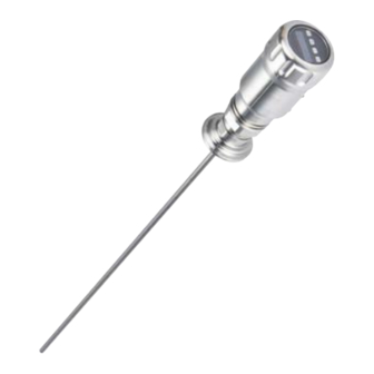
PRODUCT DESCRIPTION Product characteristics 3.2.1 Device view Fig. 1: LFP Inox (standard version) 1 Inactive part of the probe 2 Sample probe 3 Electrical connection 4 Display 5 Operating buttons 3.2.2 Operating buttons The sensor is operated using the display and the operating buttons. -
Page 13: Product Features And Functions
The sensor is not affected by changes in the properties of the liquids to be measured. Its hygienic design means the LFP Inox is suitable for universal use in all liquids in the food industry. -
Page 14: Transport And Storage
TRANSPORT AND STORAGE Transport and storage Transport For your own safety, please read and observe the following notes: IMPORTANT Damage to the sensor due to improper transport. • The device must be packaged for transport with protection against shock and damp. •... -
Page 15: Mounting
B ≥ 10 mm Distance to built-in components in container ≥ 100 mm Fig. 2: LFP Inox Coaxial tube in metallic and non-metallic containers C = No minimum distance to the container wall and to built-in components needs to be maintained with a coaxial probe. -
Page 16: Installation In A Metal Immersion Tube Or Metal Bypass
“17 Accessories” are to be observed (insert note). 5.1.2 Installation in a metal immersion tube or metal bypass Fig. 3: LFP Inox Centering LFP Inox D ≥ DN 40 Distance bypass floor / container floor B ≥ 15 mm Centering: To prevent contact between the probe and the bypass pipe during oscilla- tions, the probe should be centered according to its length and depending on the diam- eter of the bypass pipe. -
Page 17: Mounting The Coaxial Tube
MOUNTING Mounting the coaxial tube See the operating instructions for the coaxial tube (8015674) at www.sick.com. Shortening the probe If the mono-probe is too long for use, it can be shortened to the height of the container. In this case, you should not shorten the probe beyond its minimum length of 100 mm. -
Page 18: Electrical Installation
ELECTRICAL INSTALLATION Electrical installation Safety 6.1.1 Notes on the electrical installation IMPORTANT Equipment damage due to incorrect supply voltage! An incorrect supply voltage may result in damage to the equipment. • Only operate the device using a protected low voltage and safe electrical insulation as per protection class III. -
Page 19: Electrical Connection
Once installed, the sensor is ready for operation on completion of the self-test (< 5 s) and the display shows the current measured value. Fig. 4: LFP Inox 6.2.2 Pin assignment, M12 plug connector, 5-pin Fig. -
Page 20: Pin Assignment, M12 Plug Connector, 8-Pin
ELECTRICAL INSTALLATION 6.2.3 Pin assignment, M12 plug connector, 8-pin Fig. 6: M12 x 1 plug connector, 8-pin Contact Marking Description Supply voltage Switching output 2, PNP / NPN Ground, reference potential for current / voltage output Switching output 1, PNP / IO-Link Switching output 3, PNP / NPN Switching output 4, PNP / NPN Analog current / voltage output... -
Page 21: Commissioning
COMMISSIONING Commissioning Quick commissioning (with factory settings) Quick commissioning is used in applications under reference conditions, “5 Mounting”. Where the following applies: • Use in metallic containers or immersion / bypass pipes • Situations where the liquid to be measured has a DK value of > 5; see “18 Medi- list”. - Page 22 COMMISSIONING Commissioning Mount the sensor as appropriate to the installation conditions, see “5 Mounting”. Log in to expert mode, see “8.4.1 Expert mode”. Select measuring mode. • Access the EXPRT-CONFIG-MeasMd menu using the arrow and Set pushbut- tons. • HiSpd: max. length = 2,005 mm, response time < 400 ms •...
-
Page 23: Foam Commissioning (With Factory Settings)
COMMISSIONING Note: • Use the foam commissioning instructions for applications with foam. • The sensor automatically quits expert mode after 5 minutes of inactivity on the display. • Configuration (AutCal) does not take place in the following processes: • Changing the probe length •... - Page 24 COMMISSIONING Note: • Measurement deviation may be higher. • Signal quality 1 and 2 are not counted • The sensor automatically quits expert mode after 5 minutes of inactivity on the display. • Configuration (foam teach) does not take place in the following processes: •...
-
Page 25: Operation
IO-Link For operation via IO-Link, an IODD file and a description of the available telegram parameters can be downloaded from www.sick.com. 8019921/15H0 / 2019-09-30| S I C K A G O P E R AT I N G I N S T R U C T I O N S | L F P I N O X... -
Page 26: Configuring The Switching Outputs
OPERATION Configuring the switching outputs 8.2.1 Switching hysteresis and window function Depending on 2 or 4 output variants Level If the level is fluctuating around the set value (e.g., ripple movement during filling), the hysteresis keeps the switching status of the outputs stable. When the level is increasing, the output switches when the respective high... -
Page 27: Normally Open With Configurable Hysteresis
OPERATION 8.2.2 Normally open with configurable hysteresis Applications • Dry run protection • Empty signal Configuration Configure the Qx switching output as normally open. • Set the parameter in the QxMENU-OUx menu to Qx_Hno. Set the switching point. • Set the value in the QxMENU-SPx menu to level in mm (e.g., 500 mm). Set the reset point. -
Page 28: Normally Closed With Configurable Hysteresis
OPERATION 8.2.3 Normally closed with configurable hysteresis Applications • Overfill protection • Full signal Configuration Configure the Qx switching output as normally closed. • Set the parameter in the QxMENU-OUx menu to Qx_Hnc. Set the switching point. • Set the value in the QxMENU-SPx menu to level in mm (e.g., 500 mm). Set the reset point. -
Page 29: Normally Open With Window Function
OPERATION 8.2.4 Normally open with window function Application The critical fill level for the application is within the FHx and FLx window thresholds. Configuration Configure the Qx switching output as normally open. • Set the parameter in the QxMENU-OUx menu to Qx_Fno. Set the switching point. -
Page 30: Normally Closed With Window Function
OPERATION 8.2.5 Normally closed with window function Application The critical fill level for the application is outside the FHx and FLx window thresholds. Configuration Configure the Qx switching output as normally closed. • Set the parameter in the QxMENU-OUx menu to Qx_Fnc Set the switching point. -
Page 31: Normally Open With Error Signal
OPERATION 8.2.6 Normally open with error signal Application If there is an error message on the LFP, this can be transferred using a switching con- tact. Configuration Configure the Qx switching output as normally open. • Set the parameter in the QxMENU-OUx menu to Qx_Eno. Select the electrical property [NPN/PNP/DRV (push/pull)] Select the parameter in the QxMENU-TYPx menu. -
Page 32: Configuring The Analog Output
OPERATION Configuring the analog output 8.3.1 Automatic signal detection The LFP can automatically detect which signal is required using the connected output load. Where the following applies: • 4 mA to 20 mA < 500 ohms at Uv > 15 V •... -
Page 33: Advanced Functions
OPERATION Set lower limit value (0 V). • Set the value in the QAMENU-QALOW menu to level in mm (e.g., 10 mm). Invert the signal. The analog signal can be inverted in the QAPOL menu. Set the parameter in the QxMENU-QAPOL menu to QA-INV. •... -
Page 34: Automatic Interference Signal Limit Adjustment
OPERATION 8.4.3 Automatic interference signal limit adjustment The interference signal limit (TrsHld) can be adjusted automatically in many applica- tions. Configuration Set the level to 30%. Log in to expert mode, see “8.4.1 Expert mode”. Run EXPRT-Pulse-AutoTn in the menu. The sensor identifies a suitable value for TrsHld. -
Page 35: Selecting Evaluation Process
OPERATION Configuration Log in to expert mode, see “8.4.1 Expert mode”. Define the parameter in the EXPRT-Config-MaskZn menu. Note: This setting can only be used in Pulse mode. 8.4.5 Selecting evaluation process You can switch between Pulse mode and Foam mode for the evaluation process. Different evaluation algorithms are used depending on the mode selected. -
Page 36: Configuring The Probe Length
OPERATION Activate the QA analog output Set the parameter in the QAMENU-SimCur or SimVol menu to the desired signal value. • SimCur for current output • SimVol for voltage output Note: The simulation is automatically deactivated if the supply voltage is interrupted. Simulating the level Even if there is no liquid in the container yet, it is possible to select a fill level in the menu in order to test the sensor configuration. -
Page 37: Teaching In Static Interference Signals
OPERATION 8.4.8 Teaching in static interference signals Static interference signals in the tank generated by pipes, struts, couplings, or cleaning balls can be taught in. The probe length provides the value for the teach-in depth. Log in to expert mode, see “8.4.1 Expert mode”. -
Page 38: Changing The Coaxial Cable Length
OPERATION SigQa2 Characteristic for the robustness of echo pulse detection in relation to interference pulses. Not active in foam mode. The displayed value is only valid if the sensor displays the correct level value. • Value range: 0 to 100% •... -
Page 39: Activating The Display Lock
OPERATION 8.4.11 Activating the display lock To prevent the sensor from being tampered with, password protection can be activated for the display. When the protection is active, the expert password (000537) must be entered before the menu can be accessed. The menu is only unlocked once the correct password is entered. -
Page 40: Setting The Offset
Configuration Log in to expert mode, see “8.4.1 Expert mode”. Set the offset in the EXPRT-Config-Offset menu (0 to 3,000 mm) Fig. 7: LFP Inox Level QALOW/QAHIGH SPx/RPx FHx/FI x Can only be set in this zone O: Offset... -
Page 41: Resetting The Calibration
OPERATION 8.4.14 Resetting the calibration Reset AutCal Log in to expert mode, see “8.4.1 Expert mode”. Reset AutCal in the EXPRT-Pulse-Reset menu. Reset CalEmp+CalMed Log in to expert mode, see “8.4.1 Expert mode”. Reset CalEmp+CalMed in the EXPRT-Foam-Reset menu. 8019921/15H0 / 2019-09-30| S I C K A G O P E R AT I N G I N S T R U C T I O N S | L F P I N O X Irrtümer und Änderungen vorbehalten... -
Page 42: Menu Overview
MENU OVERVIEW Menu overview Q1MENU Value 1000 mm Value Para SimQ1 Para Q2/3/4MENU SP2/3/4 Value RP2/3/4 Value FH2/3/4 Value FL2/3/4 Value OU2/3/4 Para Para TYP2/3/4 Para SimQ2/3/4 QAHIGH QAMENU Value QALOW Value QAPOL Para QATYP Para QAFAIL Para SimCur Para Para SimVol Para... - Page 43 Para SimCur MENU OVERVIEW Para SimVol DspVal Para Filter Para SimLev Para RstFac CALL.. EXPRT Conf ig Lock Para Unit Para Offset Value Mode Para MeasMd Para MaxCol Value Pulse AutCal Cal.OK TrsHld Value AutoTu Cal.OK CalRng Value MaskZn Value MaskTr Value Reset...
- Page 44 MaskZn Value MENU OVERVIEW MaskTr Value Cal.OK Reset Foam CalEmp Cal.OK CalMed Cal.OK Limit Value Reset Cal.OK Probe Length Value CblLen Value Type Para Info FrmVer Value SerNo Value CalSta Value AppTag Value DevTag Value SigQua SigQa1 Value SigQa2 Value SigQa3 Value PASSW...
-
Page 45: Overview Of Parameters
OVERVIEW OF PARAMETERS Overview of parameters Parameter Description Q1MENU, Q2MENU, “8.2 Configuring the switching outputs”. Q3MENU, Q4MENU Switching point, switching output 1 or 2 or 3 or 4 (SPx > RPx). Note: Not displayed if the switching output in the OUx menu is set to error or window. - Page 46 OVERVIEW OF PARAMETERS Parameter Description QATYP Output signal settings • 4 mA ... 20 mA • 0 V ... +10 V • Auto V = Qa operated with voltage output of 0 V ... +10 V • Auto A = Qa operated with current output of 4 mA ...
- Page 47 AutCal process. During the AutCal process, there must not be any medium in the defined area of +200 mm. “8.4.8 Teaching in static interference signals” (LFP Inox). MaskZn “8.4.4 Blanking interference signals in masked zone”. MaskTr “8.4.4 Blanking interference signals in masked zone”.
- Page 48 OVERVIEW OF PARAMETERS Parameter Description Reset Resets the values for CalEmp and CalMed. Probe Probe settings. Length “8.4.7 Configuring the probe length”. CblLen “8.4.10 Changing the coaxial cable length”. Type Choose either Rod (probe rod) or Rope (cable probe). Info Sensor information.
-
Page 49: Troubleshooting
TROUBLESHOOTING Troubleshooting 11.1 Error message on the display Error Cause Solution !InvEc & AutCal not executed, source of interference super- Perform commissioning imposed on medium reflection level present (see “7.1 Quick commissioning (with factory settings)”). TrsHld setting is not suitable for the medium Perform advanced commissioning (see “7.2 Advanced... -
Page 50: Operating The Display
TROUBLESHOOTING Error Cause Solution The display only The Menu-DspVal menu parameter is at QaBarG Change QALOW or DspVal shows RUN. It is and the level is below QALOW. otherwise empty. Display off Temperature too high Reduce the temperature Temperature too low Increase the temperature No supply voltage Connect sensor correctly... -
Page 51: Outputs
TROUBLESHOOTING 11.3 Outputs Error Cause Solution Switching output Configuration incorrect Perform configuration of the switching output does not behave as (see “8.2 Configuring the switching outputs”). expected An error is pending; the sensor outputs are in the Remove the cause of the error safe state. -
Page 52: Repair
The return form is available from our website (www.sick.com). O P E R AT I N G I N S T R U C T I O N S | L F P I N O X 8019921/15H0 / 2019-09-30 | S I C K A G Irrtümer und Änderungen vorbehalten... -
Page 53: Disposal
DISPOSAL Disposal Dispose of device components and packaging materials in compliance with applicable country-specific waste treatment and disposal regulations for the region of use. 8019921/15H0 / 2019-09-30| S I C K A G O P E R AT I N G I N S T R U C T I O N S | L F P I N O X Irrtümer und Änderungen vorbehalten... -
Page 54: Technical Data
TECHNICAL DATA Technical data 14.1 Features Medium Liquids Detection type Limit, continuous Probe length 200 mm ... 4,000 mm Adjustable measuring range 95 mm ... 6,005 mm Process pressure –1 bar ... +16 bar Process temperature –20 °C ... +150 °C EHEDG certificate ... -
Page 55: Mechanical/Materials
TECHNICAL DATA 14.3 Mechanical/materials Wetted parts 1.4404 (Ra ≤ 0.8 μm), PEEK Process connection G 3/4 (hygienic process connectors with adapter for G 3/4, see accessories), 3/4 NPT Housing material 1.4305 Max. probe load 6 Nm Enclosure rating IP67: EN 60529, IP69K: EN 40050 Coaxial cable insulation Electrical cable insulation Version with electrical cable instead of M12 connection. -
Page 56: Electrical Connections
TECHNICAL DATA 14.6 Electrical connections Supply voltage 12 V DC ... 30 V DC Current consumption ≤ 100 mA at 24 V without output load Initialization time ≤ 5 s Protection class Connection type M12 x 1 (5-pin) M12 x 1 (8-pin) Hysteresis Min. -
Page 57: Measurement Accuracy
TECHNICAL DATA 14.7 Measurement accuracy Measurement accuracy with parameterized container L-25 L-180 Accuracy in mm Level in mm Measurement accuracy without parameterized container L-40 L-180 Accuracy in mm Level in mm Inactive area 8019921/15H0 / 2019-09-30| S I C K A G O P E R AT I N G I N S T R U C T I O N S | L F P I N O X Irrtümer und Änderungen vorbehalten... -
Page 58: Dimensional Drawings
DIMENSIONAL DRAWINGS Dimensional drawings LFP Inox standard version 54 (2.13) 36 (1.42) (1.26) G 3/4 A 3/4" NPT M12x1 G 3/4 A 3/4" NPT 7 (0,28) Mono-probe with coaxial tube Measuring range 20 (0.79) Probe length Inactive area at process connection 25 mm... - Page 59 DIMENSIONAL DRAWINGS LFP Inox with remote amplifier 36 (1.42) 6 (0.24) (1.57) 54 (2.12) 36 (1.42) 40 (1.57) G 3/4 A 3/4" NPT 38 (1.50) 7 (0.28) Length of cable Measuring range Probe length Inactive area at process connection 20 mm / 40 mm...
-
Page 60: Factory Setting
FACTORY SETTING Factory setting Parameter Factory setting 80% of the probe length measured from the end of the probe 5 mm below SP1 Q1_Hno For 5-pin versions: 20% of the probe length measured from the end of the probe For 8-pin versions: 60% of the probe length measured from the end of the probe 5 mm below SP2 Q2_Hno TYP2... -
Page 61: Accessories
Accessories can be found online at: www.sick.com 8019921/15H0 / 2019-09-30| S I C K A G O P E R AT I N G I N S T R U C T I O N S | L F P I N O X... -
Page 62: Medium List
MEDIUM LIST Medium list This medium list provides a guide to the DK values of liquids. Water-based liquids always have a DK value of > 5, which allows LFP to be used easily. For DK values of < 5, a coaxial tube or a metallic immersion tube / bypass is always required. - Page 63 MEDIUM LIST Substance Substance Substance value value value Dibenzofuran (100 °C) Green vitriol (80 °C) 32.4 Urea Dibenzyl (60 °C) Ferrozell 18.3 Resin Diesel fuel Fat coal Hazelnuts Diethylamine Fatty acid (35 °C) Hot glue (150 °C) Dimethylether (methyl ether) Fish oil Heating oil Diofan...
- Page 64 MEDIUM LIST Substance Substance Substance value value value Isobutyl chloride Coke Methylene bromide Isobutyl cyanide Cork powder Methylene chloride Isobutyl iodide Concentrated feed Methylene chloride Isobutyl nitrate 11.7 Chalk Methylene iodide Isobutyl silane Cresol Methyl nitrate 23.5 Isoquinoline 10.7 Cresol resin 18.3 Methyl cellulose Isocyanate...
- Page 65 MEDIUM LIST Substance Substance Substance value value value Palmitic acid Popcorn Soft soap Palm tree nuts Liquid detergent Chocolate powder Palm tree nuts Propanal (15 °C) 14.4 Black liquor Palm seed oil Propanol (propyl alcohol) Sulfur Paper scraps Propanoic acid Sulfur dioxide (sulfurous acid) Paraffin...
- Page 66 MEDIUM LIST Substance Substance value value Terpinolene Xylene Tetrachloroethylene Toothpaste 18.3 Carbon tetrachloride Cellulose Thomaskali dust Cement Thujone (0 °C) 10.8 Zinc oxide Meat and bone meal Zinc powder Titan tetrachloride Sugar Toluene Tinder Clay Transformer oil Trichloroethylene Triethyl aluminum Triptane Dry yeast Ultrasil...
- Page 67 NOTES 8019921/15H0 / 2019-09-30| S I C K A G O P E R AT I N G I N S T R U C T I O N S | L F P I N O X Irrtümer und Änderungen vorbehalten...
- Page 68 Phone +852 2153 6300 Phone +421 482 901 201 E-Mail ghk@sick.com.hk E-Mail mail@sick-sk.sk Hungary Slovenia Phone +36 1 371 2680 Phone +386 591 78849 E-Mail ertekesites@sick.hu E-Mail office@sick.si Further locations at www.sick.com SICK AG | Waldkirch | Germany | www.sick.com...
Need help?
Do you have a question about the LFP INOX and is the answer not in the manual?
Questions and answers