Table of Contents
Advertisement
Available languages
Available languages
Quick Links
Advertisement
Chapters
Table of Contents

Subscribe to Our Youtube Channel
Related Manuals for SICK LBV 321 NAMUR


Summary of Contents for SICK LBV 321 NAMUR
- Page 1 B E T R I E B S A N L E I T U N G LBV 321 - NAMUR...
-
Page 2: Table Of Contents
Inhaltsverzeichnis Inhaltsverzeichnis Zu diesem Dokument Funktion........Zielgruppe ....... . Verwendete Symbolik . - Page 3 Inhaltsverzeichnis Maße........32 Sicherheitshinweise für Ex-Bereiche Beachten Sie bei Ex-Anwendungen die Ex-spezifischen Sicherheits- hinweise.
-
Page 4: Zu Diesem Dokument
1 Zu diesem Dokument 1 Zu diesem Dokument 1.1 Funktion Die vorliegende Betriebsanleitung liefert Ihnen die erforderlichen Informationen für Montage, Anschluss und Inbetriebnahme sowie wichtige Hinweise für Wartung und Störungsbeseitigung. Lesen Sie diese deshalb vor der Inbetriebnahme und bewahren Sie sie als Produktbestandteil in unmittelbarer Nähe des Gerätes jederzeit zugänglich auf. -
Page 5: Zu Ihrer Sicherheit
2 Zu Ihrer Sicherheit 2 Zu Ihrer Sicherheit 2.1 Autorisiertes Personal Sämtliche in dieser Betriebsanleitung beschriebenen Handhabungen dürfen nur durch ausgebildetes und vom Anlagenbetreiber autorisier- tes Fachpersonal durchgeführt werden. Bei Arbeiten am und mit dem Gerät ist immer die erforderliche persönliche Schutzausrüstung zu tragen. -
Page 6: Sicherheitskennzeichen Am Gerät
2 Zu Ihrer Sicherheit 2.5 Sicherheitskennzeichen am Gerät Die auf dem Gerät angebrachten Sicherheitskennzeichen und - hinweise sind zu beachten. 2.6 CE-Konformität Dieses Gerät erfüllt die gesetzlichen Anforderungen der zutreffenden EG-Richtlinien. Mit der Anbringung des CE-Zeichens bestätigen wir die erfolgreiche Prüfung. 2.7 Sicherheitshinweise für Ex-Bereiche Beachten Sie bei Ex-Anwendungen die Ex-spezifischen Sicherheits- hinweise. -
Page 7: Produktbeschreibung
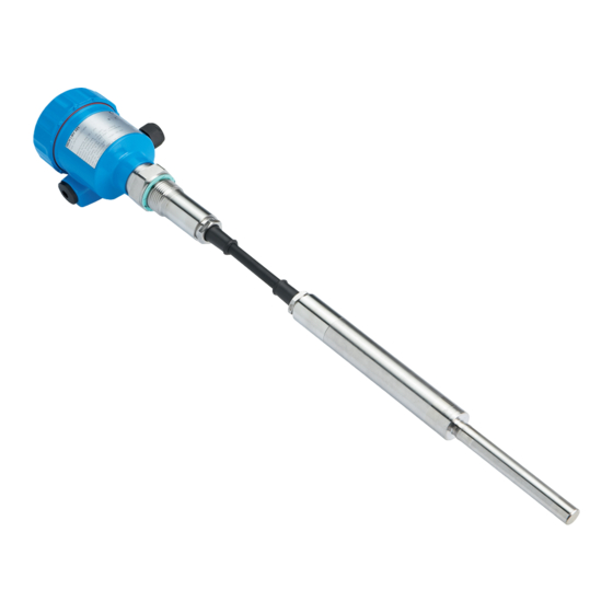
3 Produktbeschreibung 3 Produktbeschreibung 3.1 Aufbau Der Lieferumfang besteht aus: Lieferumfang Grenzstandsensor LBV 321 Dokumentation Dieser Betriebsanleitung Ex-spezifischen "Sicherheitshinweisen" (bei Ex-Ausführun- gen) Ggf. weiteren Bescheinigungen Der LBV 321 besteht aus den Komponenten: Komponenten Gehäusedeckel Gehäuse mit Elektronik Prozessanschluss mit Schwingstab Abb. -
Page 8: Arbeitsweise
3 Produktbeschreibung Zusätzlich zum Typschild außen am Gerät finden Sie die Serien- nummer auch im Inneren des Gerätes. 3.2 Arbeitsweise Der LBV 321 ist ein Grenzstandsensor mit Schwingstab zur Einsatzbereich Grenzstanderfassung. Er ist konzipiert für industrielle Einsätze in allen Bereichen der Verfahrenstechnik und wird vorzugsweise in Schüttgütern eingesetzt. -
Page 9: Bedienung
3 Produktbeschreibung 3.3 Bedienung In der Werkseinstellung können Füllgüter mit einer Dichte > 0,05 g/cm³ (0.002 lbs/in³) gemessen werden. Bei Füllgütern mit niedriger Dichte > 0,02 g/cm³ (0.0007 lbs/in³) kann das Gerät angepasst werden. Auf dem Elektronikeinsatz finden Sie folgende Anzeige- und Bedie- nelemente: Kontrollleuchte zur Anzeige des Schaltzustandes (gelb) Potentiometer zur Anpassung an die Füllgutdichte... -
Page 10: Montieren
4 Montieren 4 Montieren 4.1 Allgemeine Hinweise Eignung für die Pro- Stellen Sie sicher, dass sämtliche, im Prozess befindlichen Teile des zessbedingungen Gerätes, insbesondere Sensorelement, Prozessdichtung und Pro- zessanschluss für die auftretenden Prozessbedingungen geeignet sind. Dazu zählen insbesondere Prozessdruck, Prozesstemperatur sowie die chemischen Eigenschaften der Medien. -
Page 11: Montagehinweise
4 Montieren Bei Über- oder Unterdruck im Behälter müssen Sie den Prozessan- Druck/Vakuum schluss abdichten. Prüfen Sie vor dem Einsatz, ob das Dichtungs- material gegenüber dem Füllgut und der Prozesstemperatur beständig ist. Den maximal zulässigen Druck können Sie dem Kapitel "Technische Daten"... - Page 12 4 Montieren Abb. 3: Befüllung und Entleerung mittig LBV 321 • - NAMUR...
- Page 13 4 Montieren Abb. 4: Befüllung mittig, Entleerung seitlich LBV 321 Entleeröffnung Befüllöffnung Das Schwingelement sollte möglichst frei in den Behälter ragen, um Stutzen Ablagerungen zu verhindern. Vermeiden Sie deshalb Stutzen für Flansche und Einschraubstutzen. Dies gilt vor allem für Füllgüter, die zu Anhaftungen neigen.
- Page 14 4 Montieren Abb. 5: Einströmendes Füllgut Prallschutz gegen Stein- Bei Anwendungen z. B. in Sandfängen oder in Absetzbecken für schlag Grobsedimente ist das Schwingelement mit einem geeigneten Prall- blech vor Beschädigungen zu schützen. Dieses Prallblech müssen Sie selbst anfertigen. > 125 mm ") Abb.
-
Page 15: An Die Spannungsversorgung Anschließen
5 An die Spannungsversorgung anschließen 5 An die Spannungsversorgung anschließen 5.1 Anschluss vorbereiten Sicherheitshinweise be- Beachten Sie grundsätzlich folgende Sicherheitshinweise: achten Nur in spannungslosem Zustand anschließen In explosionsgefährdeten Bereichen müssen die entsprechenden Sicherheitshin- weise für Ex- Vorschriften, Konformitäts- und Baumusterprüfbescheinigungen der Sensoren und der Versorgungsgeräte beachtet werden. -
Page 16: Anschlussplan Einkammergehäuse
5 An die Spannungsversorgung anschließen Kabel durch die Kabelverschraubung in den Sensor schieben Öffnungshebel der Klemmen mit einem Schraubendreher an- heben (siehe nachfolgende Abbildung) Abb. 7: Anschlussschritte 5 und 6 Aderenden nach Anschlussplan in die offenen Klemmen stecken Öffnungshebel der Klemmen nach unten drücken, die Klemmen- feder schließt hörbar Korrekten Sitz der Leitungen in den Klemmen durch leichtes Ziehen prüfen... - Page 17 5 An die Spannungsversorgung anschließen Gehäuseübersicht Abb. 8: Werkstoffvarianten Einkammergehäuse Kunststoff (nicht bei EEx d) Aluminium Edelstahl, elektropoliert Filterelement für Luftdruckausgleich Zum Anschluss an Trennverstärker nach NAMUR (IEC 60947-5-6, Anschlussplan EN 50227). Weitere Informationen finden Sie im Kapitel "Technische Daten". Weitere Informationen finden Sie im Kapitel "Technische Daten", "Ex- technische Daten"...
-
Page 18: Anschlussplan - Ausführung Ip 66/Ip 68, 1 Bar
5 An die Spannungsversorgung anschließen 1 2 3 4 Abb. 10: Anschlussplan - Externe Simulationstaste NAMUR-Trennschaltverstärker Brücke Externe Simulationstaste 5.4 Anschlussplan - Ausführung IP 66/IP 68, 1 bar Aderbelegung An- schlusskabel Abb. 11: Aderbelegung Anschlusskabel Braun (+) und blau (-) zur Spannungsversorgung bzw. zum Auswertsystem Abschirmung LBV 321 •... -
Page 19: In Betrieb Nehmen
6 In Betrieb nehmen 6 In Betrieb nehmen 6.1 Allgemein Die Zahlenangaben in Klammern beziehen sich auf die nachfolgenden Abbildungen. Auf dem Elektronikeinsatz finden Sie folgende Anzeige- und Bedie- Funktion/Aufbau nelemente: Potentiometer zur Anpassung an die Füllgutdichte (1) DIL-Schalter zur Betriebsartenumschaltung - min./max. (2) Simulationstaste (3) Kontrollleuchte (6) 6.2 Bedienelemente... -
Page 20: Funktionstabelle
6 In Betrieb nehmen Das Potentiometer des LBV 321 steht ab Werk auf Rechtsanschlag (> 0,3 g/cm³ bzw. 0.011 lbs/in³). Bei besonders leichten Schüttgütern drehen Sie das Potentiometer auf Linksanschlag (0,02 … 0,1 g/cm³ bzw. 0.0007 … 0.0036 lbs/in³). Damit wird der LBV 321 empfindlicher und kann leichte Schüttgüter sicherer detektieren. -
Page 21: Wiederkehrender Funktionstest
6 In Betrieb nehmen Füllstand Signalstrom - Sen- Kontrollleuchte Fallende Kennlinie ≥ 2,4 mA max. Fallende Kennlinie ≤ 1 mA max. Steigende Kennlinie ≥ 2,4 mA min. Steigende Kennlinie ≤ 1 mA min. Störung beliebig ≤ 1 mA blinkt 6.4 Wiederkehrender Funktionstest Gemäß... - Page 22 6 In Betrieb nehmen Einrichtungen beobachtet werden. Der Sensor muss somit weder ausgebaut noch durch Befüllen des Behälters zum Ansprechen gebracht werden. Dies gilt für LBV 321 mit dem NAMUR-Elektronik- einsatz VB60N. Sie können den Funktionstest mit den ausgegebenen Stromwerten auch direkt über eine SSPS oder ein Prozessleitsystem durchführen.
- Page 23 6 In Betrieb nehmen Sensor- Füllstandre- Füllstandre- Kontroll- Kontroll- Kontroll- strom lais Trenn- lais Trenn- leuchte leuchte leuchte - schaltver- schaltver- Trenn- Trenn- Sensor stärker - stärker - schaltver- schaltver- Überlauf- stärker - stärker - Trocken- schutz laufschutz Überlauf- Trocken- schutz laufschutz ca.
-
Page 24: Instandhalten Und Störungen Beseitigen
7 Instandhalten und Störungen beseitigen 7 Instandhalten und Störungen beseitigen 7.1 Wartung Bei bestimmungsgemäßer Verwendung ist im Normalbetrieb keine besondere Wartung erforderlich. 7.2 Störungen beseitigen Verhalten bei Störungen Es liegt in der Verantwortung des Anlagenbetreibers, geeignete Maßnahmen zur Beseitigung aufgetretener Störungen zu ergreifen. Der LBV 321 bietet Ihnen ein Höchstmaß... -
Page 25: Elektronikeinsatz Tauschen
7 Instandhalten und Störungen beseitigen Fehler Ursache Beseitigung Falsche Kennlinie Korrekte Kennlinie am Kennlinienum- gewählt kehrschalter einstellen (Überlauf- schutz, Trockenlaufschutz). Die Verkabelung sollte nach dem Ruhe- stromprinzip ausgeführt werden. Kontrollleuchte Fehler am Kontrollieren Sie, ob das Schwing- blinkt gelb Schwingelement element beschädigt oder stark korro- diert ist. -
Page 26: Das Gerät Reparieren
14 Kabelverschraubung auf Dichtigkeit überprüfen. Der Dichtring muss das Kabel komplett umschließen. 15 Gehäusedeckel verschrauben Der Elektroniktausch ist somit abgeschlossen. 7.4 Das Gerät reparieren Sollte eine Reparatur erforderlich sein, wenden Sie sich bitte an die zuständige Sick-Vertretung. LBV 321 • - NAMUR... -
Page 27: Ausbauen
8 Ausbauen 8 Ausbauen 8.1 Ausbauschritte Warnung: Achten Sie vor dem Ausbauen auf gefährliche Prozessbedingungen wie z. B. Druck im Behälter, hohe Temperaturen, aggressive oder toxische Füllgüter etc. Beachten Sie die Kapitel "Montage" und "An die Spannungsversor- gung anschließen" und führen Sie die dort angegebenen Schritte sinngemäß... -
Page 28: Anhang
9 Anhang 9 Anhang 9.1 Technische Daten Allgemeine Daten Werkstoff 316L entspricht 1.4404 oder 1.4435 Werkstoffe, medienberührt Prozessanschluss - Gewinde 316L Prozessanschluss - Flansch 316L Prozessdichtung Klingersil C-4400 Dichtung (Schwingelement) CR, CSM Schwingstab 316L, 318 S13 (1.4462) Tragkabel (-20 … +80 °C/-4 … +176 °F) Tragkabel - optional (-40 …... - Page 29 9 Anhang Ausgangsgröße Ausgang Zweileiter-NAMUR-Ausgang Stromaufnahme Kennlinie fallend (max.) ≥ 2,4 mA unbedeckt/≤ 1 mA bedeckt Kennlinie steigend (min.) ≤ 1 mA unbedeckt/≥ 2,4 mA bedeckt Störmeldung ≤ 1 mA Erforderliches Auswertsystem NAMUR-Auswertsystem nach IEC 60947-5-6 (EN 50227/DIN 19234) Betriebsarten (NAMUR-Ausgang umschaltbar auf fallende oder steigende Kennlinie) Min.
- Page 30 9 Anhang Elektromechanische Daten - Ausführung IP 66/IP 68 (1 bar) Kabeleinführung Einkammergehäuse 1 x IP 68-Kabelverschraubung M20 x 1,5; 1 x Blindstopfen M20 x 1,5 oder: 1 x Verschlusskappe ½ NPT, 1 x Blindstopfen ½ NPT Anschlusskabel Aufbau vier Adern, ein Tragseil, eine Druckausgleichska- pillare, Schirmgeflecht, Folie, Mantel Leitungsquerschnitt 0,5 mm²...
- Page 31 9 Anhang Aluminium- und Edelstahlgehäuse (op- IP 66/IP 68 (1 bar) tional) Überspannungskategorie Schutzklasse Zulassungen Geräte mit Zulassungen können je nach Ausführung abweichende technische Daten haben. Bei diesen Geräten sind deshalb die zugehörigen Zulassungsdokumente zu beachten. Diese sind im Gerätelieferumfang enthalten. LBV 321 •...
- Page 32 9 Anhang 9.2 Maße LBV 321 ~ 59 mm ~ 69 mm (2.32") ~ 116 mm (4.57") ø 80 mm (2.72") ø 79 mm ø 86 mm (3.39") (3.15") (3.11") M20x1,5/ M20x1,5/ M20x1,5 M20x1,5/ ½ NPT ½ NPT ½ NPT Abb.
- Page 33 9 Anhang 1 / 2 ø 29 mm (1.14") ø 11 mm (0.43") ø 29 mm (1.14") ø 16 mm (0.63") Abb. 31: LBV 321 - mit PUR-Tragkabel Sensorlänge, siehe Kapitel "Technische Daten" LBV 321 • - NAMUR...
- Page 34 9 Anhang 1 / 2 ø 29 mm (1.14") ø 10 mm (0.39") ø 29 mm (1.14") ø 16 mm (0.63") Abb. 32: LBV 321 - mit FEP-Tragkabel Sensorlänge, siehe Kapitel "Technische Daten" LBV 321 • - NAMUR...
- Page 35 9 Anhang LBV 321 • - NAMUR...
- Page 36 LBV 321 39163-DE-110617...
- Page 37 O P E R A T I N G I N S T R U C T I O N S LBV 321 - NAMUR...
- Page 38 Contents Contents About this document Function........Target group ......Symbolism used.
- Page 39 Contents Dimensions ....... 32 Safety instructions for Ex areas Please note the Ex-specific safety information for installation and operation in Ex areas.
-
Page 40: About This Document
1 About this document 1 About this document 1.1 Function This operating instructions manual provides all the information you need for mounting, connection and setup as well as important instructions for maintenance and fault rectification. Please read this information before putting the instrument into operation and keep this manual accessible in the immediate vicinity of the device. -
Page 41: For Your Safety
2 For your safety 2 For your safety 2.1 Authorised personnel All operations described in this operating instructions manual must be carried out only by trained specialist personnel authorised by the plant operator. During work on and with the device the required personal protective equipment must always be worn. -
Page 42: Safety Label On The Instrument
2 For your safety 2.5 Safety label on the instrument The safety approval markings and safety tips on the device must be observed. 2.6 CE conformity This device fulfills the legal requirements of the applicable EC guidelines. By attaching the CE mark, we provide confirmation of successful testing. -
Page 43: Product Description
3 Product description 3 Product description 3.1 Structure Scope of delivery The scope of delivery encompasses: LBV 321 point level switch Documentation this operating instructions manual Ex-specific "Safety instructions" (with Ex versions) if necessary, further certificates The LBV 321 consists of the components: Constituent parts Housing cover Housing with electronics... -
Page 44: Principle Of Operation
3 Product description 3.2 Principle of operation Application area LBV 321 is a point level sensor with vibrating rod for level detection. It is designed for industrial use in all areas of process technology and is preferably used for bulk solids. Typical applications are overfill and dry run protection. -
Page 45: Storage And Transport
3 Product description Mode switch to select the switching condition (reverse character- istics) Simulation key 3.4 Storage and transport The device was protected by packaging during transport. Its capacity Packaging to handle normal loads during transport is assured by a test according to DIN EN 24180. -
Page 46: Mounting
4 Mounting 4 Mounting 4.1 General instructions Suitability for the proc- Make sure that all parts of the instrument exposed to the process, in ess conditions particular the sensor element, process seal and process fitting, are suitable for the existing process conditions. These include above all the process pressure, process temperature as well as the chemical properties of the medium. -
Page 47: Mounting Instructions
4 Mounting The process fitting must be sealed if there is gauge or low pressure in Pressure/Vacuum the vessel. Before use, check if the seal material is resistant against the measured product and the process temperature. The max. permissible pressure is specified in chapter "Technical data" or on the type label of the sensor. - Page 48 4 Mounting Fig. 3: Filling and emptying centred LBV 321 • - NAMUR...
- Page 49 4 Mounting Fig. 4: Filling in the centre, emptying laterally LBV 321 Discharge opening Filling opening The vibrating element should protrude into the vessel to avoid buildup. Socket For that reason, avoid using mounting bosses for flanges and screwed fittings. This applies particularly to use with adhesive products. Inflowing medium If LBV 321 is mounted in the filling stream, unwanted false measure- ment signals can be generated.
- Page 50 4 Mounting Fig. 5: Inflowing medium Baffle protection against In applications such as grit chambers or settling basins for coarse falling rocks sediments, the vibrating element must be protected against damage with a suitable baffle. This baffle must be manufactured by you. >...
-
Page 51: Connecting To Power Supply
5 Connecting to power supply 5 Connecting to power supply 5.1 Preparing the connection Note safety instructions Always keep in mind the following safety instructions: Connect only in the complete absence of line voltage Take note of In hazardous areas you must take note of the respective regulations, safety instruc- conformity and type approval certificates of the sensors and power tions for Ex ap-... -
Page 52: Wiring Plan, Single Chamber Housing
5 Connecting to power supply Fig. 7: Connection steps 5 and 6 Insert the wire ends into the open terminals according to the wiring plan Press down the opening levers of the terminals, you will hear the terminal spring closing Check the hold of the wires in the terminals by lightly pulling on them Tighten the compression nut of the cable entry. - Page 53 5 Connecting to power supply Housing overview Fig. 8: Material versions, single chamber housing Plastic (not with EEx d) Aluminium Stainless steel, electro-polished Filter element for air pressure compensation Wiring plan For connection of the amplifier according to NAMUR (IEC 60947-5-6, EN 50227).
-
Page 54: Wiring Plan - Version Ip 66/Ip 68, 1 Bar
5 Connecting to power supply 1 2 3 4 Fig. 10: Wiring plan - External simulation key NAMUR amplifier Bridge External simulation key 5.4 Wiring plan - version IP 66/IP 68, 1 bar Wire assignment con- nection cable Fig. 11: Wire assignment connection cable brown (+) and blue (-) to power supply or to the processing system Shielding LBV 321 •... -
Page 55: Set Up
6 Set up 6 Set up 6.1 General information The figures in brackets refer to the following illustrations. On the electronics module you will find the following indicating and Function/Configuration adjustment elements: Potentiometer for adaptation to the product density (1) DIL switch for mode adjustment - min./max. -
Page 56: Function Chart
6 Set up As a default setting, the potentiometer of LBV 321 is set to the complete right position (> 0.3 g/cm³/0.011 lbs/in³). In very light solids you have to turn the potentiometer to the complete left position (0.02 … 0.1 g/cm³ or 0.0007 … 0.0036 lbs/in³). By doing this, LBV 321 will be more sensitive and light solids can be detected more reliably. -
Page 57: Recurring Function Test
6 Set up Signal current - Control lamp Level Sensor Falling characteris- ≥ 2.4 mA tics max. Falling characteris- ≤ 1 mA tics max. Rising characteris- ≥ 2.4 mA tics min. Rising characteris- ≤ 1 mA tics min. Failure ≤ 1 mA flashes 6.4 Recurring function test According to IEC 61508. - Page 58 6 Set up Simulation key on the A function test can be carried out for measurement setups in conjunction with the NAMUR electronics module VB60N. For this electronics module purpose, the switching delay must be set to 0.5 s. LBV 321 has an integrated simulation key.
- Page 59 6 Set up Sensor cur- Level relay Level relay Signal lamp Signal lamp Signal lamp rent amplifier - amplifier - amplifier - amplifier - - sensor overflow dry run pro- overflow dry run pro- protection tection protection tection 2. High Current approx.
-
Page 60: Maintenance And Fault Rectification
7 Maintenance and fault rectification 7 Maintenance and fault rectification 7.1 Maintenance If the instrument is used properly, no special maintenance is required in normal operation. 7.2 Fault rectification Reaction when malfunc- The operator of the system is responsible for taking suitable measures to rectify faults. -
Page 61: Exchanging The Electronics Module
7 Maintenance and fault rectification Error Cause Removal Wrong character- Set the correct characteristics on the istic selected characteristics reversal switch (over- flow protection, dry run protection). Wiring should be carried out accord- ing to the quiescent current principle. Signal lamp Error on the vi- Check if the vibrating element is flashes yellow... -
Page 62: Instrument Repair
14 Check cable gland on tightness. The seal ring must completely encircle the cable. 15 Screw the housing cover on The electronics exchange is now finished. 7.4 Instrument repair If it is necessary to repair the instrument, please contact the responsible Sick agency. LBV 321 • - NAMUR... -
Page 63: Dismounting
8 Dismounting 8 Dismounting 8.1 Dismounting steps Warning: Before dismounting, be aware of dangerous process conditions such as e.g. pressure in the vessel, high temperatures, corrosive or toxic products etc. Take note of chapters "Mounting" and "Connecting to power supply" and carry out the listed steps in reverse order. -
Page 64: Supplement
9 Supplement 9 Supplement 9.1 Technical data General data Material 316L corresponds to 1.4404 or 1.4435 Materials, wetted parts Process fitting - thread 316L Process fitting - flange 316L Process seal Klingersil C-4400 Seal (vibrating element) CR, CSM Vibrating rod 316L, 318 S13 (1.4462) Suspension cable (-20 …... - Page 65 9 Supplement Output variable Output Two-wire NAMUR output Current consumption Falling characteristics (max.) ≥ 2.4 mA uncovered/≤ 1 mA covered Rising characteristics (min.) ≤ 1 mA uncovered/≥ 2.4 mA covered Fault message ≤ 1 mA Necessary processing system NAMUR processing system according to IEC 60947-5-6 (EN 50227/DIN 19234) Modes (NAMUR output adjustable to falling or rising characteristics) Min.
- Page 66 9 Supplement Electromechanical data - version IP 66/IP 68 (1 bar) Cable entry Single chamber housing 1 x IP 68 cable gland M20 x 1.5; 1 x blind stopper M20 x 1.5 1 x closing cap ½ NPT, 1 x blind plug ½ NPT Connection cable Structure four wires, one suspension cable, one breather...
- Page 67 9 Supplement Aluminium and stainless housing (op- IP 66/IP 68 (1 bar) tionally available) Overvoltage category Protection class Approvals Depending on the version, instruments with approvals can have different technical data. For these instruments, please note the corresponding approval documents. They are included in the scope of delivery.
- Page 68 9 Supplement 9.2 Dimensions LBV 321 ~ 59 mm ~ 69 mm (2.32") ~ 116 mm (4.57") ø 80 mm (2.72") ø 79 mm ø 86 mm (3.39") (3.15") (3.11") M20x1,5/ M20x1,5/ M20x1,5 M20x1,5/ ½ NPT ½ NPT ½ NPT Fig.
- Page 69 9 Supplement 1 / 2 ø 29 mm (1.14") ø 11 mm (0.43") ø 29 mm (1.14") ø 16 mm (0.63") Fig. 28: LBV 321 - with PUR suspension cable Sensor length, see chapter "Technical data" LBV 321 • - NAMUR...
- Page 70 9 Supplement 1 / 2 ø 29 mm (1.14") ø 10 mm (0.39") ø 29 mm (1.14") ø 16 mm (0.63") Fig. 29: LBV 321 - with FEP suspension cable Sensor length, see chapter "Technical data" LBV 321 • - NAMUR...
- Page 71 9 Supplement LBV 321 • - NAMUR...
- Page 72 LBV 321 39163-EN-110621...
Need help?
Do you have a question about the LBV 321 NAMUR and is the answer not in the manual?
Questions and answers